

saiello
-
Posts
21 -
Joined
-
Last visited
Never
saiello's Achievements
")
Newbie (1/14)
0
Reputation
-
Hi All, I'm looking for a cheap and easy way to transfer my circuit onto copper board. I'm using a piece of software that can print the tracks 1:1 on a printer. I'm aware of the various methods out there, photoboard+UV light, transfers, laser printer/toner method, etch-pen, etc. I came across a paper product that allows you to print a graphic using an inkjet printer and transfer it onto a T-shirt using an iron. Would this work? Has anyone has tried this? Thanks, Salvatore.
-
Hi audioguru, I've checked the datasheet for the LM311 and according to the Electrical Characteristics table the response time is 200nS given a 100mV input step and 5mV overdrive(?) which appears to be the very much the same as the LM6511 which has a 180nS response time with a 100mV input step and 25mV overdrive, again as indicated by the Electrical Characteristics table. I found the graph you attached in the LM311 datasheet, but I also found one ( see attached ) that appears to show that the LM311 is capable of much faster switching and which also ties in with the values that the table shows. I'm a tad confused as to which graph I should be refering to..!
-
Hi, Will this circuit work ( see attached )? I've determined that the worst case scenario is that a 1uS flash of light needs to be detected with a 66us delay before the next flash. Once I get this last problem nailed down I can build my board! SFH2030F.pdf
-
Great! There's the SFH2030 that has a rise/fall time of 5nS! Currently the phototransistor in my circuit is supplied with 5V and acts as an input to a LM311N comparator. Can I use the photodiode as a drop-in replacement for the phototransistor or will there be issues I need to address? Thanks, Salvatore.
-
Hi, I'm using a phototransistor ( SFH300-3 ) in my circuit that has rise/fall times of around 10uS. I need a phototransistor that will respond to 2uS or quicker pulses of light. When the manufacturer specifies a rise time for example, does this mean that the phototransistor has to be illuminated for this length of time for it to reach it's full gain given a certain voltage drop and illumination? Or, will it respond to shorter length pulses, where the rise/fall times are just reaction times and that the full gain will eventually be reached after the rise time has elapsed? If this isn't that case, is it possible to improve the response time of a phototransistor or will I simply need to source a better performing one? Thanks, Salvatore.
-
Couldn't you use a comparator that takes both inputs. When the output is zero, the signals are at the same voltage, i.e. 'crossed', then all you have to do is to take a reading from one of the inputs for the actual value.
-
Hi, If you can determine what values for R1/C1/C2 I need to solve the problem please let me know! :D Will the cmos inverters just invert the signal? If this is the case then it won't solve the problem as a
-
Hi, I think I've found the problem! :D There's a formula in the datasheet for determining the maximum frequency that can be input: Fmax=I2/C1*Vcc=0.00018/(0.0000000047*7.57)=5060Hz. At this frequency, the half cycle pulse width would be 0.098ms which from my testing turns out to be just about the value that I determined was starting to give me problems. So the only solution I can see is to increase the pulse width at source, i.e. somehow delay the pulse generated by the phototransistor so that it remains a constant at around 0.1ms regardless of the input frequency or duty cycle. Anyone know how I might go about doing this? Maybe somehow using a capacitor on the input to the comparator to store the charge for a short time? I've attached a diagram of the input stage to give a clearer idea. Thanks, Salvatore.
-
Hi audioguru! I remember you helping me out on my comparator problem!
-
Hi All, I've almost finished my project for a tachometer circuit. Testing went well until I appear to have hit upon a snag for which I need some help. It concerns the LM2917N frequency to voltage converter IC, which I can happily 'program' to give the correct output with a given frequency input ( 0-2500Hz ) using a frequency generator. The problem arose when I tried to vary the 'duty cycle' of the input frequency ( which is a square wave ), i.e. I adjusted the 'HI' time to make it a smaller percentage of the time 'LO'. Whatever frequency I input, if I adjusted the HI so that it was less than 0.1ms ( 0.0001s ), the voltage output from the LM2917N started to drop. I've tested the LM2917N with higher input frequencies with a Hi/Lo duty cycle of around 50% giving half-cycles much less than 0.1ms, and it still outputs a voltage ( although off the scale ). It is important that the LM2917N can accept low duty cycle input frequencies as it will be generated from a laser diode/phototransistor pair reflected off a rotating body where duty cycles can be as low as 1%. I've also tried testing using the laser diode/ phototransistor as the input in a 'real' test situation, i.e. reflecting off a rotating nut. With a given output voltage if I gradually block off the light recieved by the phototransistor, I start to get the same erroneous result, i.e a drop in output voltage, indicating that the reducing duty cycle is to blame. I've checked the datasheet for any issues concerning this but I can't seem to find anything relating to this. Has anyone had any experience of this? Any help much appreciated! :) Thanks, Salvatore.
-
Spot on!
-
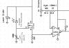
Hi Again! ;D Following on from the problem with the comparator ( which is now solved, thanks! ), I've since progressed with my circuit and have managed to get things more or less working. This sub-circuit is ultimately to act as a light detector ( using a laser diode as the light source ) to serve as input to a larger tachometer circuit measuring frequencies up to 2500Hz. The output of the comparator will be fed into the HCF4018B CMOS divide-by-N IC which will function as a first stage frequency divider. I've attached a schematic of the light detector, the blue and red parts depicting alternative versions. The blue part ( 10K pot ) is for testing the switching function, the red part ( Laser diode and phototransistor ) is as it is supposed to be in the final circuit. In testing the circuit ( using the 10K pot ) the switching seems fine, the hysteresis behaves as it should and the LED on the comparator output switches on an off as expected. I then added the red part of the circuit ( I took a guess at the 10K value of the pull-up resistor ) and initially things seem to work fine, switching the output LED on when the photo transistor is exposed to the light from the laser. On further tests I noticed that when VERY SLOWLY introducing the phototransistor to another light source ( a household lamp bulb ) that the LED wouldn't switch fully on, it would start to glow, brightening more and more as exposure to the light bulb increased. I investigated the output voltage of the comparator and found that it was swinging very slowly. With the +ve input of the comparator set at a threshold of +2.5V the comparator output starts to drop when the –ve input rises to just +2.2V, within 0.3V of the threshold. The current passing through the phototransistor at this point is around 400uA. This is a very similar result to the one that I had when I made the mistake of using too high a pot on one of the inputs. I suspect that I have the same problem here with the phototransistor not being able to provide enough current for the comparator to work properly. I swapped the phototransistor and resistor around and changed the resistor for a 1K, the thinking being that if I supply enough current first and then drain it with the phototransistor things would work better but I seem to be getting similar problems. Is it possible to boost the current in some simple way ( if this is indeed the problem! ) while maintaining the same input signal? Thanks in advance!
-
Hi All, Well after all that, it turns out that the 1K pot I'd replaced the 1M pot was in fact also a 1M pot... doh..!!
-
Hi, I've attached a schematic ( I hope! ). I've changed the 1M pot to a 1K pot. Results are exactly the same as the previous tabulated results. Cheers, Salvatore.
-
Hi, To keep things simple, I've reduced the circuit to not include hysteresis. I can't seem to find how to attach a schematic (sorry!), but the circuit is literally the LM393, +5V supply to the comparator and two pots, one 1Mohm for the -ve reference input and a 10K for the +ve input, all connected to ground. The output of the comparator has a 2K pull-up resistor.
