

walid
-
Posts
749 -
Joined
-
Last visited
Never
Content Type
Profiles
Forums
Events
Posts posted by walid
-
-
Hi guru
The base input impedance of the transistor at low audio frequencies
is its beta of about 200, times the emitter resistance of 220 plus
its internal emitter resistance = 44.5k ohms. It is in parallel with
the two 47k resistors also in parallel, so the load on the mic is
15.4k ohms.
This is good, but I want to introduce the effect of the 1nF cap on the lower 47Kohm.
The reactance of that cap at freqs from 300Hz t0 15Khz is 10.6 Kohm to 53 Kohm
47K // 10.6K = 8.65 K, and
47K // 53K = 24.9K
so VB is not constant at VB = 9 * 47/(47+47) = 4.5v as i was think
it is really changes from 1.4V to 3.12V with the audio freq
Now Zin (total) = ZB//RB1//RB2
since RB2 equivalant is change from 8.65 K to 24.9K
so Zin change
please comment.It is complicated to calculate how much is the output voltage and current because tapping down
the coil reduces the output voltage into the low impedance antenna but provides a better
impedance match so the collector voltage swing is much higher.
I agree that it is complicated to calculate how much is the output voltage and current, lets
assume them and investigate the tapping effect on them:
If the output voltage = 5mV rms at freq 100MHz as shown in the Fig. below, how much voltage reach the antenna?
and what the value of the impedance the antenna see, if the coil is 330nH and its XL = 207 ohm at 100MHz?
thank u guru
-
Good evening Guru
Thank u for fast and good replyThis is a very simple filter. At the cutoff frequency the response is down -3dB which is a small amount. If the cutoff frequency is 500Hz then 50Hz would be reduced but not eliminated.
Now I'll not ask you about filters and the -3dB, I'll postpone this to another discussion, but I noticed that C1 and the other Rs are not intended as a filter.
You choosed C1 as the smallest possible cap to couple the two parts of the circuit, and not els.Only at high frequencies and if there is no load.
At high frequencies, to what range?
To a freq make Xc4 = R5, if so, to f=2258Hz a human voice.At 15kHz, the reactance of the 150nF C4 capacitor
is 1070 ohms in parallel with R5= 71.1 ohms.
Xc4 at 15KHz = 70.7 ohm in parallel with R5= 61.5 ohms, not so far.
I know this is not problem, and this occur whe somebody do fast calculation.Therefore at 15kHz the voltage gain is about 0.707 x 10k/(71.1 + 86.70= 63.4.
Two questions:
(1) why u choose the 15KHz personally?
(2) I understand [10k/(71.1 + 86.70)] but not 0.707
I know that 1/sqr(2) = 0.707
but why multiplying the Av by it, is it a known formula?At 300Hz, the reactance of ....
this statement answer the #1 question above, 300Hz is the lower limit of the human voice and the 15KHz is the upper limit.At 300Hz, the reactance of the 150nF C4 capacitor is 53.5k so it doesn't affect the gain. Then the voltage gain is only 10k/(470 + 86.7)= 18. So the treble boost at 15kHz is about 3.5 times.
The idea is very clear and you provide me with a very good and new information, but to others who may read our discussion, I tell them GURU has some headache because he answring hunreds of questions every day, GOD save guru from any bad thing.
At 300Hz, the reactance of the 150nF C4 capacitor is 3.5k
3500//470 = 414 ohm
Then the voltage gain is only 10k/(414 + 86.7)= 20. So the treble boost at 15kHz is about 3.2 times. NO DIFFERENCE
GURU you are good man and "Electronics Lab - Community = GURU"
Thank u for every word you write to help me.
-
Hi guru
u enlarge the discussion and introduce a new aspects -at least foe me- and i can -
Thank you guru it is evident and good answer
-
Hi guru
please look at the Fig below. It is thr first stage of your FM TX
I omit C2 to make it more simple to discussNegative feedback reduces a transistor's voltage gain and distortion and increases its bandwidth and input impedance.
Where is the Negative feedback in your circuit (below)If a current source is used as the collector resistor or bootstrapping is used then the voltage gain is high and the distortion is low. But the output impedance is high so an emitter-follower is needed at the output.
please put some examples to a current source and bootstrapping and how they connected to collector
you guru add a CE to your Tx
thank you
-
Hi
I said before, at 12/6/2006 that:Later I'll continue my discussion about:
bypassing the whole RE
bypassing part of RE
choosing the caps value between stages
discussing a real designs and show if this is good or bad ...
today I'll discuss with audioguru and you, the effect of adding a bypass cap to RE, its name is CE
Till now we can design a perfect voltage divider BJT transistor configuration without CE
When adding this CE, two circuit parameters are changes:
(1) The voltage gain Av now = RC/re and not as before adding CE it was RC/RE.
With CE, you get mor Av, and distortion takes place.
(2) The i/p impedance seen at the base, ZB, ZB = hfe*re, it is very smaller compared with the case without CE (ZB = hfe*(re+RE)).
I think that the total Zin (= RB1//RB2//ZB) will not affected much because of the paralle connection.
my question: are there any other parameter affected by adding CE, and
Why we disregard the distortion accompanying with the increased Av?
thank you -
Hi
when we come to design a high pass filter like that formed between stages
Here C is the coupling cap
and R is the i/p impedance of the next stage
the cutoff freq = 1/(2 pi R C)
To make the cutoff freq = say 100 Hz, u can:
take C = 10 uF and R = 160 ohm
OR
take C = 1 uF and R = 1.6 Kohm
You can design it with different values of R and C
MY question is what the differance between them?
thanks -
Hi guru
That circuit is nearly the same as mine, except its frequency will drift as the battery voltage runs down because it doesn't have my voltage regulator.
yes exactly, i noticed this. I'll redesign it after your help, and with u makeing its range more.
I know that this circuit is not better than yours, but I have a chance with this.
when I build a circuit and didn't work it is more easy to me to build anthother new one than searching for the problem in the first, it is very complex and make headache. it is hard to me, after 4 hours of work and organize, to look again for the causes, especially if i use a used parts from my junk, the possibility is large.It also won't boost treble audio frequencies which are cut in FM radios.
please explain this statement.The easiest way to increase its range is to use a 9V battery instead of only 3V. But then the 1st transistor will probably saturate and will need its base resistor's value increased or its collector resistor's value decreased.
If I increase RB or decrease Rc, then I'll have more voltage gain!The microphone's powering resistor is connected directly to the battery and the supply bypass capacitor has a low value which is good for RF, so the circuit might "motorboat" until you add a 100uF supply bypass capacitor.
u mean "motorboat" after using 9 v battThe output transistor is connected without any negative feedback to control its operating point.
also your FM Tx has no -ve FBTransistors have a wide range of current gain so some have low gain and will be cutoff in this circuit and others will have high gain and the transistor will be saturated.
I need more explaination to this point.The simplest fix is to change the value of the 150k resistor to 68k then connect it to the collector instead of to the supply.
to make the last stage a collector feedback configuration, but doind this adds what to the circuit.
thank u guru
-
Hi guru
I build this circuit:
I followed exactly their instructions
I put parts very close to each other and very close to the board
it work fine
i built it in aboard with holes, and its area was 15 holes X 5 holes, it is very small and crowded with parts
i put it in my hand, so i toutch every part including antenna, and this did not affect the freq at all
I use a mic from an old tape recorder national panasonic, and i use the 39k resistor and the voice was fine
i omit only the variavle cap and depend on the coil length to slightly change the freq
the only problem is its range
in an open place its range about 50 meter only
can y help me to increase the range of this very good and very stable Tx.
thank you guru -
Hi guru
for the circuit shown below, someone ask my the following question:
Can I increase the range of this transmitter by using power transistor like BLY89 and decreasing the RE?
I attached the datasheets of BLY89
i look at that datasheets and see it max freq = 175 MHz
i think it can handle the 88MHz FM freq
i know it is can not be used in stead of that small signal transistor
but i need your explanation to make the answer reasonable.
thank u guru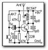
-
Hi guru
please read the following:
"The sensitivity of the WASP depends to a large extent on the value of the load resistor on the electret microphone. We have used 39k in the project, as the microphone we supply is a very sensitive type. If you wish to increase the sensitivity to super performance, the resistor can be decreased to 33k but don't go any lower otherwise the circuit may 'oscillate' or 'motor-boat.' "
this from: http://www.talkingelectronics.com/Projects/Wasp/Wasp-P1.html
please guru, comment.
thank u -
Hi guru
I have never made an electret mic but I think if its diaphraghm spacing is reduced then it will be more sensitive but then its max sound pressure level will be less.
hehehehe
I'm sure u have never made an electret mic.
somewhere i read that his mic is very sensitive and can pick up all voices inside the room, like u said about your FM Tx.
others said that you must talk near it....
from that, one deduce that it is posible to increase or decrease mic sinsivity by, say, increase Zin of the next stage, decrease R1...etec
I want your help in this point
thank you very much -
Hi guru
thank you for your efforts to explain
First, you skip my last questions with a colored table.So increasing R1 to 10k for more gain from its jFET won't make much difference.
with 1k the total = 762 ohm as u said
with 10k the total = 2424 ohm, big differenceI think the total input impedance of the mic preamp should be 30k or more and R1 should be 10k if the supply voltage allows it.
I calculate Zin at the base the Ic=0.1 mA, Zin = 52K
to make it 30K, Ic must = 0.2 mA
If i do so, what are the side effects on the circuit
another general equestion:
how the designers increase the sensivity of the mic, what they do?
thank u guru -
please don't skip the above questions, i forgot to ask this important one:
what the optimum impedance value that mic like to connect with, that is R1// Zin of the next stage?
thank u again -
Hi audioguru
The constant current becomes only a little higher when a lower resistance of R1 increases the voltage at the drain of the jFET.
yes, it is very good point. i experiment with 3 mics, applying 9 volt dc to each and measure the drawn current with 1k then 10k ohm resistors.
i had the resuls shown in the table below.
look at it, changing R from 10K to 1K increasing the current only small amount, it is really a high impedance current sink.
Now I see by my eyes that decreasing R1 value will not increase the mic current segnificantly.
OKTherefore a high load resistance allows the jFET to amplify the signal more than a low load resistance, like a transistor.
a high load resistance, u mean R1
you mean that R1 looks like RC with BJT, more RC value leads to more voltage gain.A jFET doesn't have as much voltage gain as a transistor so changing the load/powering resistance doesn't make a big difference.
as a role always take R1 = 10KThe next low impedance stage is in parallel with R1 so increasing the value of R1 won't make much difference. R1 should be about 10k so that the mic's jFET can provide some voltage gain, and the input resistance of the next stage should be more than about 30k so that it isn't a low load resistance to the output of the jFET.
If the next stage i/p impedance is in parallel with R1, and the next stage i/p impedance is 30K, then 30//10 = less than 10
and 30// 5 = less than 5, so it is not true to say: the value of R1 won't make much difference.
** the last question
If we conclude that decresing R1 will not increase the mic current, and cosequently will not increase the sensivity of the mic, and it is prefered to make R1 big value (10K), then:
1) how the designers increase the sensivity of the mic, what they do?
2)Why someone see many different values for R1 in simple FM Txs.
guru, thank you very much for everything u learned me.
walid
-
Hi guru
thank u very muchBut the mic in this simple circuit is driving the low input impedance of the transistor. Therefore the FET transistor in the mic won't have much more gain if R1 has a higher value. difference.
lets discuss it:
1- is the mic is a constant current source that its current not effected by changes in R1 value. or this current increased by decreasing R1 value.
2- the sensivity of mic is increased when more current pass through it>
3-when mic circuit driving a next low impedance stage, R1 must be low value,why? beccause a low impedance stage wants more current than a high impedance one, so the mic's current must be greater.
What abou the circuit below, its Vcc is only 1.5 v!!!!
-
Hi audioguru
after my last question, another friends take the subject to a more complex corner, so i back it to its simplist form again.
In our discussion about R1 (=10K) we conclude that most of mics drawing 0.5mA and have 1/2 vcc across them so R1 must be 5K or 4.7K, and you told me that your mic is from a telephone board and it draws only 1/4 mA so R1 =10k is ok
I understand you and all this is oK
I take these info and teach it to other friend.
today he asked me about this circuit:
he asked me the following question:
why this circuit using 1k as R1 and not 9K ?
can u help me in answring this question
thank u -
Hi guru
The transistor needs a change of base to emitter current to be an amplifier and to oscillate. If the base voltage is not secured with a capacitor to ground then it will also have its voltage changed when the positive feedback changes the emitter voltage, then there is no change in base to emitter current.
I feel that i not understand what you want to say.
Lets analyze that statement:
I assume that VE = 3v
VB = 3.7v
positive feedback changes the emitter voltage to say 4 v
so VB = 4.7v
now what that cap do to maintain VB to 3.7 v
thank u guru -
Hi guru
This circuit uses a common-base amplifier. There are many other kinds of oscillator circuits. The capacitor makes the base at 0V for RF frequencies. If it is removed then the circuit probably won't oscillate
why the circuit probably won't oscillate, can you please, explain this point more.The antenna impedance match to the circuit's output impedance is poor, but it is simple and it works
What would u do to improve the matching between o/p and antenna?The base input impedance of the transistor at low audio frequencies is its beta of about 200, times the emitter resistance of 220 plus its internal emitter resistance = 44.5k ohms. It is in parallel with the two 47k resistors also in parallel, so the load on the mic is 15.4k ohms.
beta = 200, are u guess it or depend on some source or you consider any general purpose transistor's beta as approx 200.
also you calculate the internal emitter resistance (re) as beta X re =500 ohm, that is re = 500/200 =2.5 ohm, frome this:
25/Ic=2.5 ==> Ic = 10 mA, is these values from datasheets, I search for BC547 datacheets and find many copmanies, please provide me with your datasheet or tell me from any comany.It is complicated to calculate how much is the output voltage and current because tapping down the coil reduces the output voltage into the low impedance antenna but provides a better impedance match so the collector voltage swing is much higher
But with tap, the coil acts as a step down transformer?The input audio causes the transistor to conduct more and less which changes the voltage across it and changes its capacitance.
Are you mean the capacitance between B and E?
thank you alot
-
Hi guru
Maxim's VCO IC uses a varactor diode (it changes its capacitance when its voltage is changed) to frequency-modulate and to tune its carrier.
ok, i agree
my circuit did not using a varactor diode, there is no varactor diode
i think that a p-n junction do this, is this true and how? -
i read it but i not understand any thing
it is not as i expect
can u guru point me to another article more close to what i need
can u help me in understanding carfully how this vco operate
thank u -
Hi guru
i read carefull your last reply but it was not sufficient to make me understand so, i now reading this doc.
http://www.maxim-ic.com/appnotes.cfm/appnote_number/2032
may it help me
then i'll back to u to finish this hard subject
thank u guru -
Thank you guru u are a good man
1) The 1nF cap makes the transistor a common-base amplifier at radio frequencies where the emitter is its input and the collector is its output.
why it need to be a common-base, what would be happen if we remove this 1n cap.
I know that -
the following FM circuit
I have tree questions:
1- what the function of the 1 n cap
2-why tapping the coil, why not connecting the antenna directly to the collector
3-what the function of the 1.8p cap, and why it is so small
thanx


a very simple FM Tx
in Theory articles
Posted
Hi guru

First thank u for the figures from which i can see that the 1 nF has no resonable effect at AF.
but u may not see this question
I agree that it is complicated to calculate how much is the output voltage and current, lets
assume them and investigate the tapping effect on them:
If the output voltage = 5mV rms at freq 100MHz as shown in the Fig. below, how much voltage reach the antenna?
and what the value of the impedance the antenna see, if the coil is 330nH and its XL = 207 ohm at 100MHz?
thank u guru
these flowers are for you