redwire
-
Posts
244 -
Joined
-
Last visited
Content Type
Profiles
Forums
Events
Everything posted by redwire
-
PicMaster, How come R1 and R2 in your sketch have signifcantly different values than the revised parts list?
-
When you asked me earlier about P3, I thought you were referring to point 3 from the original sketch instead of Potentiometer 3. I don't think I ever labeled it P3, so it was throwing me off. I don't have the coarse and fine Potentiometers shown on the Eagle PCB file I posted because no additional connections on the PCB are necessary to use the coarse/fine controls. Yes you intall P3 in series with P1 but you do not have it installed correctly in your sketch. On P3 you need to cut the connection between ground and point 2. Then connect pins 1 and 2 together. I think.
-
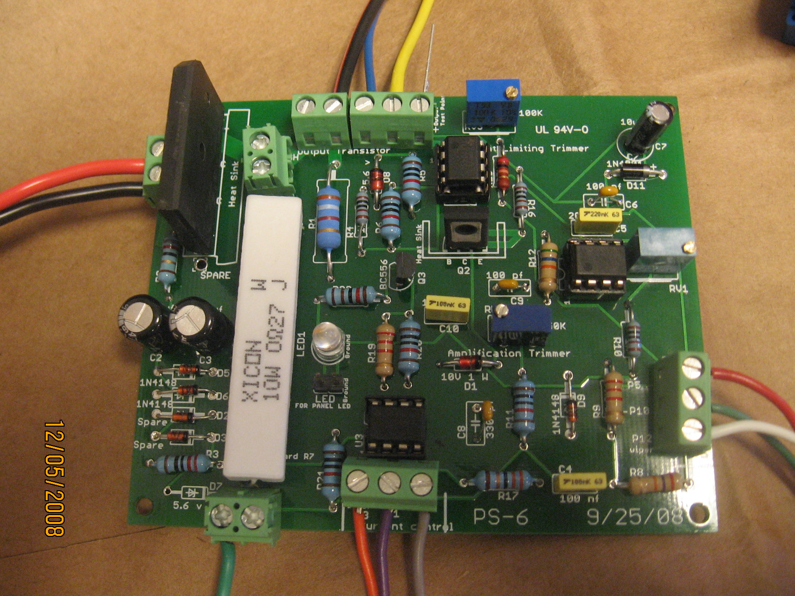
hint: look for a "3" near the top of the pcb
-
effenberg0x0 I home built my transformer from a microwave oven transformer. I cut the windings and rewound it using copper tape. My max voltage output is 58V unloaded. I don't know the rated capacity is but I've held it at 7 amps for a short period, cut it off and check the transformer for unusual heat. You can use the transformer you have, simply adjust the current adjuster trimmer so that your maximum output does not exceed the capacity of the transformer. That's the good think about the revised design. Attached is a picture of the LCD display I'm working on . I have a older version actually connected that does not show the temperature or maximum current setting of the PS. Picture.rar
-
I used a 0R27 10W cement resistor not just because I wanted a 5A version but to also reduce wasted power. The 10w version is longer than the 5W resistor so it dissipates heat better. Although you can not see it on the first post of this thread, the cement resistor is not sitting on the board but raised above it. Below it on the bottom side of the board is a large ground pad that helps dissipate heat. At 3A it only consumes 2.4 watts. I also built the pcb so that the resistor could be mounted to the frame by using an aluminum housed resistor. I found that in normal operation the 10W board mounted was not a problem.
-
effenberg wrote: Why don't you build the non SMD version that is linked to the above site. Original design page located here: http://elfly.pl/multimetr/multimetr_en.htm Yes, several have built is successfully. I have a non smd LCD version working on mine. I'll post some pictures later.
-
corsa, That looks correct. If you notice a few extra holes or pins it's because I added a few to connect the LCD display and one led connection for your front ase. It will work with or without the pins installed.
-
corsa The area contained in the blue shape on the left hand side of the pcb should all be a solid blue ground plane. I used an earlier version of EAGLE to create the pcb and I had to down load the latest version to open your copy. You need to take the original version I posted, and hit the Ratsnest button and it will fill. The copy you posted looks like you altered something because it does not fill properly.
-
Hi effenberg0x0. There are insignificant differences between audioguru's part list and mine. Mine reflect preferences rather than errors. I wanted to have a little more range so I used a 0.27ohm power resister instead of the 0.49 ohm in the original. Some of the calibration pots may have different values to fully utilize the increased amperage range but both work. After adding the 10V Zener, I reduced the value of R22 because it no longer see the output of the transformer. R2 got pretty hot so I increased the resistance a bit. The sketch attached to my post is Audioguru's so there should be no difference in the pcb.
-
Hi karthikeid I posted my pcb file a few pages up but here is the link: http://www.electronics-lab.com/forum/index.php?topic=19066.msg89170#msg89170
-
Corsa, you may be able to use the Eagle file I posted to change the double sided pcb to a single sided board. This may require some jumper wires. Note that some of the traces are quite wide to handle large currents. Most are not. If you don't want to create your own pcb send me a PM.
-
Hi Corsa, Here is the pcb in EAGLE for the board at the top of the thread. It is a double sided board because I had it produced at a professional shop. It is somewhat of a challenge to build double sided boards at home. Note that D2 and D3 need to be filled with a 1N4148 and D7 is not used for the latest version. Good luck EDIT: After opening board file in Eagle, hit Ratsnet to fill ground plane under R7 PS-6.rar
-
Zsyt may be able to use the transformer with the revised design posted at the beginning of the thread. RV3 is used to regulate the max output to stay within the parameters of the transformer and board.
-
Yes, it goes with the sketch you posted. For the 5A version I would recommend the following: 1. 30VAC 7.2A or higher stepdown transformer 2. R7 = 0.27, 10W resistor 3. C1= 20,000 uf, 63V 4. Q4, Q5 & Q6 (at least 3 paralleled ) NPN transistors on huge heatsinks. Actually pretty minor changes since most of these parts are located off the PCB because of their size . The basic PCB doesn't change much except to ensure the tracks are wide enough to handle the 5A.
-
Here is the latest parts list I have. Not sure if it matches Audioguru's list, but if it doesn't that's what this forum is all about. PS_Parts_List_10-11-09.pdf
-
Thanks, Now we have a sketch and some parts. We can continue the discussion.
-
Audioguru, do you have a copy of the last parts list using the alternate chips. I seem to remember some of revisions were in red. EDIT: The first post contains REV 5 in the zip file. Audioguru's post directly above this also contains the same update. No need to read the next 125 pages except for fun
-
We seem to have lost the extensive discussion on this power supply topic. I attached what I believe is the latest version. NOTE the parts list included in the attached zip file is REV 5 dated 12/13/13 and covers the next 125 pages of this tread. 0-30V.zip
-
Hi, Josko, you may want to be cautious about using a pcb designed for 3-5 amps and try to pump 12A through it. Although most of the components will only experience ma's, a few tracing will need to supply the full 12 A. Make sure they are wide enough. Also your main cap will need to be huge and will not be able to fit on the pcb.
-
rcakto For the large cap you have lots of options to use, one, two or parallel several. On one build I used 3 of these 661-EKMH630VNN562MR (mouser part #) It doesn't need to be exactly 12,000uf.
-
Hi BlAzink pdo59 provided original Eagle files and code for the 2 line display here http://www.electronics-lab.com/forum/index.php?topic=12409.msg68409#msg68409 and http://www.electronics-lab.com/forum/index.php?topic=12409.msg68894#msg68894. I used this to build the unit with some minor modifications. I believe Pin 25 on the Atmega8 chip is not actually used even though the sketch shows it connected to R1 and R2. In simple terms I hooked up a wire from Point 13 on the original Power Supply sketch which is the wiper of P2, and connected it to Pin 25. The voltage at Point 13 controls the allowable current for the powersupply. I can vary it from 0-1.7v . On my power supply I used a 0.27ohm resistor for R7 so using V=IR , V is read by the ADC and R is known so the program computes what current can be allowed based on the setting of P2 then send that value to the lcd. By turning P2 on the power supply (0 to 1.7v) the allowable current is computed and displayed on the lcd. For temperature, I used a 3 pin temperature sensor such as a MCP9700a or a FM50??. I ran a wire from the 5v regulator on the ammeter to power it. One wire to the ground, and the output wire goes to a ADC pin on the Atmega 8. Then through much trial and error I revised the code to read two additional ADC pins, calculate, and display the results.
-
I think a common 1N4001 diode would work for both D1 and D2. Note that the full rectified voltage of the power supply enters D2 and goes to the 12V voltage regulators. The upper limit of the voltage regulator is around 32v so there is a good possibility that the voltage being supplied is at the regulator's limit. To correct this I added a 12V 5w zener diode right after D2 to burn off 12V before it gets to the regulator. This brings the voltage into the 12V regulator well within its limits. You will still need a heat sink for the 12V regulator. The 5V regulator runs cool. I initially used a 18V 5W zener but found it got quite hot and the 12V with heat sink was cool when using the fan. Using the 12V zener balanced it out a bit.