

Mukhalled
-
Posts
137 -
Joined
-
Last visited
Never
Content Type
Profiles
Forums
Events
Posts posted by Mukhalled
-
-
Hi,
I've built this project in a wiring board and it works, so I'm studying the whole ciruit now... but i wonder what function the diode D1 together with R2 has ???
And if i want to increase the frequency of the (piezo sounder and the LED), i can easily decrease the resistance (R3) or the capacitance (C1), right?
Thanks in advance -
Hi,
I'm trying to build this circuit in CirCad (all components are SM), it's almost imposible to get the PCB without errors ... it has to be short somewhere. My question: is there any automatic way to build the PCB in that program (CirCad)?
Any suggestions please!
Thanks in advance -
Thank you so much Audioguru for the help ;D
I'll ask again if i face a trouble ... :) -
Hello,
Can i use surface mounted capacitors instead of the two capacitors in this curcuit?
http://www.electronics-lab.com/projects/oscillators_timers/008/index.html
And what's the value of C2 ? is it nano, piko ...? and can i use a LED instead of the piezo sounder (just to indicate). -
That part model (7447) in Multisim is known to be faulty over a few issues. Even in the latest release it is still not working. They never bothered to fix it. Use a 74HC4543 or 4543 to get it working
Thanks to inform me about the 7447, i didn't find 4543 in multisim so i used 4511 instead (but changed the display to "commen cathode" instead) and finally it's working now ... Thanks again -
Hi Mukhalled,
I haven't used old TTL ICs for many years and I have lost my TTL Cookbook.
The datasheet for the 74LS90 shows an inverting clock input pin 14, so I think it counts each time it goes low.
Yes, i think so too that it should count when it goes low. But it doesn't in the simulating program ??? -
Connect that to your input pulse you want to count. It won't count on its own. The count pulse must be a logic level input
i connect pin 14 to pulse generator (1Hz, 10Vp-p), but it doesn't count... i think there is something wrong in the circuit i connect in Multisim. -
Hello,
I tried to simulate this circuit http://www.electronics-lab.com/projects/misc/012/index.html in Multisim, should pin 14 (count in) be connected to a 5V or GND or ...?
Can you help me please ;D -
Hi Audioguru,
Yeah, i saw it. It's so cool, amazing products... they are the leader in automotive audio systems. ;D ( speakers, amps, navigators ... in best cars Lexus , Porsche & Chrysler ... ;D) -
aha, thanks for the info ;D
-
Hi,
Is "Harman Kardon" a swedish enterprise/company?
I'm just curious to know... ;D
Thanks -
Hi Mr. Audioguru,
Thanks for the explanation of the "fake" power of the car stereo ;D
Yes im sorry i forgot to say how the speakers were wired. I chose 8ohm each to get 4ohm in parallel connection.
Thanks in advance -
Hi,
Fig. A is a normal connenction of car stereo which has 4-channels. Can i connect like fig. B? What are the consequences, if there are? Can the stereo be overlaoded?
Thanks in advance.
-
Hi,
I've a digital sattelite reciever (samsung) which doesn't detect any signal... I'm sure that the dish is in right position (my other reciever is detecting signal and working normally at the same position of the dish). Do you think it's a physical wrong for eg (module or something like that) or ... ?
Thanks :) -
Hi again,
It works now ;D. I've changed the board and the two capacitors.
Thank you Audioguru for the help :) -
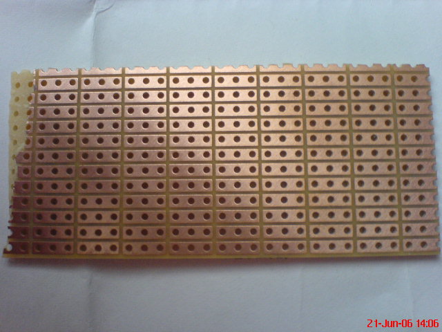
Ok, i will change the board ... do you think this board is good (attachment)?
Sorry they were Tantalum capacitors which i used not ceramic, should i change them too, to electrolytic?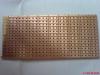
-
I didn't use the pcb layout on the datasheet.
The IC doesn't get hot when in use ...
I used ceramic capacitors (polarized) C1, C2 ? they don't need to be elctrolytic, right? -
I've tried to connect it directly to the car battery, but it's still the same problem ...
I've checked out another web-shop to be sure about the differences between these ICs and it looked like this attachment: they are two different ICs.
-
The DC voltage between pin 8 and 10 is about 1,6V.
Impedance 4 ohm
I use headphones output as an input to the power amp.
I've tried with 14V power supply, -
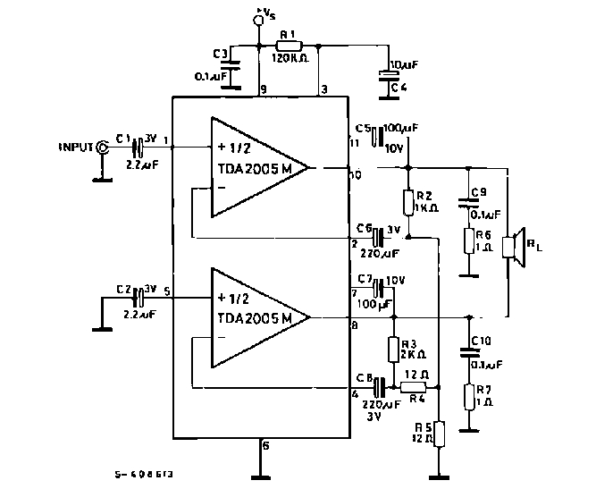
Ok, I've attached it again and i hope it's clearer now...
the supply voltage i use is 9V.
The only difference between my circuit and this schematic is that i use the tda2005 S , not tda2005 M, so i dont know if it works.
-
Hi Mukhalled,
Attach the schematic of your bridged TDA2005 for us to see what is wrong with it.
The only difference on the datasheets between the TDA2005M (for a bridged amp) and the TDA2005S (for a stereo amp) is that the TDA2005M is selected for a max output offset voltage of 150mV. Then it will have a max DC current in a 3.2 ohm speaker of 150mV/3.2 ohms= 47mA without a signal which also creates heat. The TDA2005S doesn't have an output offset voltage spec so it could be too high for a bridged amp.
Hi Mr. Audioguru,
I was waiting for your answer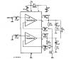
-
From the datasheet it looks like the TDA2005M and TDA2005S are both the same.
They are dual amps - 10W each
There are plenty of application configurations for mono and stereo.
Hope it helps -
Hi friends,
Are TDA2005S and TDA2005M diffirent? I know S = Stereo and M = Mono, but can i for ex connect TDA2005S as a bridge? I did it but it didn't work !! ???
The stereo one gives 2 x 10W and the mono gives 20W.
Please help ;D -
Hi,
I need to fix my TV NOKIA 6352 NICAM. The picture has a concave shape like this:
I think i have to change a little capacitor in the module but the problem is i don't know where is it in the module ??? so i need a schematic ...
Do anyone have an idea about this problem and how to fix it?
Thanks


Timed Beeper...need help!
in Projects Q/A
Posted
aha okay, thanks ;D