

HarryA
-
Posts
451 -
Joined
-
Last visited
-
Days Won
23
Content Type
Profiles
Forums
Events
Everything posted by HarryA
-

MOSFET Power module and gate drive connections guidance
HarryA replied to mumartahir's topic in Power Electronics
You can get technical support here: https://www.monolithicpower.com/en/products/ev1909-tl-00a.html -
Promac TV Universal Remote Codes & Program Instructions
-
Automatic electric bell using wifi
HarryA replied to PS ADITHYAN's topic in Electronic Projects Design/Ideas
If you search on the internet for "Automatic electric bell using wifi "you will find numerous articles on the subject: like: https://www.youtube.com/watch?v=jkG9sUWc1CA -
https://search.yahoo.com/search?p=2381BG-2-6&fr=opensearch
-
Dfplayer with Arduino pushbutton and led fading
HarryA replied to abhishek gyani's topic in Projects Q/A
What does not work? The LED fade or the mp3 player? What do you wish the push button to do? A: Push the button once and the LED fades on and off until you push it again. B: The LED fades on and off while you hold the button down. Releasing it the fading LED stops. -
Dfplayer with Arduino pushbutton and led fading
HarryA replied to abhishek gyani's topic in Projects Q/A
I am not sure what you need but here is code that fades a LED up and down. It does not block your code by using Delay(), You can paste it into your Loop{} or call it as a function. You may wish to play with the int period value and the +/-5 value. Do note which i/o pins you can use with this PWM code. //use pins 3, 5, 6, 9, 10, and 11 on the UNO const int ledPin = 3; //whichevery pin you choose Do not forget the resistor! int period = 10; //how fast to fade the LED:100 = 1/10 sec. etc unsigned long time_now = 0; //have not read the time yet int brightness = 0; //start with LED off boolean IncreaseBrightness = true; //start with increasing brightness void setup() { pinMode(ledPin, OUTPUT); Serial.begin(9600); //you may have this; used here for testing } void loop() { // non-blocking delay if(millis() > time_now + period) //get current time and compare { time_now = millis(); //for next time //fade LED up or down if(IncreaseBrightness) { analogWrite(ledPin, brightness +=5 ); if(brightness >= 255) IncreaseBrightness = false; //max ouput to LED = 255 } else //must be decreasing brightness { analogWrite(ledPin, brightness -=5 ); if(brightness <= 0 ) IncreaseBrightness = true; //min ouput to LED = 0 } } //some code...testing displays values..... Serial.print("brightness "); Serial.println(brightness); } -
You could use a microprocessor that has a a/d (analog to digital) converter. Use an op amp (operational amplifier) to increase 20mV signal for the a/d converter get reasonable results.
-
Guitar feedback issue at high frequencies - please help
HarryA replied to Sam_sky's topic in Electronics chit chat
I prototyped a couple of passive notch filter circuits including the one Tony posted. But neither were very good; two broad. If I can find an inductor between 150 to 200 mh I will try a parallel resonant band stop filter. This site maybe helpful: 8 Ways Of Resolving The Electric Guitar Feedback Problem -
Guitar feedback issue at high frequencies - please help
HarryA replied to Sam_sky's topic in Electronics chit chat
What you need is a notch filter to remove only a narrow band of unwanted frequencies . There are pedal notch filters on the market but they are pricey. Search on "guitar notch filter pedal". Also see:: https://lambdageeks.com/notch-filter/#:~:text=A notch filter%2C also known as a frequency,while allowing other frequencies to pass through unaffected. About half way down the page he covers guitar pedals. If you wish to make one perhaps I could help you with it. -
It looks good to me. I would go with it. Are you building something interesting?
-
See: Introduction to PMIC - Part 1
-
Why not read books that interest you? For example:: Digital Design and Computer Architecture
- 1 reply
-
- 1
-

-
Perhaps you could convert the alternator output directly to dc without a transformer to 300vdc (or about) and use a 127-350 dc to 24 v dc dc/dc converter to get 24 volts. See: DC/DC converter 250V to 24V, 960W
-
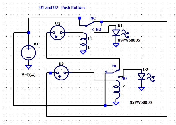
How about this? Without showing the resistors.
-
I do not see the connections to relay's NC contacts for each LED. The red LED most get its current through the NC contacts of the Green LED's relay. And the green LED must get its current through the NC contacts of the red LED's relay. Thus when one relay is active the other LED can not receive current through the the now open NC contacts.
-
Hello, I am not very knowledgeable on wifi routers so I can not offer much help. This web site maybe helpful:Improve Your Wi-Fi Speed in 10 Simple Steps On my Frontier router if you type into the browser a certain number/code it brings up a rather sophisticated user interface which maybe helpful to you if you can find the code for your router.
-
allowing 0.1 volt or greater “filter” in 12v DC
HarryA replied to ElectroPete's topic in Electronic Projects Design/Ideas
Perhaps a voltage comparator? See: Comparator You could use the 12 volts to trigger a relay that supplies a voltage to the timer? The relay should require more than 10 volts to trigger the relay to avoid the rewind? It is not clear where the 0.0009 volt and 0.1 volt signal comes from. -
see: https://www.youtube.com/results?search_query=wifi+antenna
-
When a post is made the forum software often displays key technical words in the post description. This would suggest that one could use that software to detect post that are legitimate from others. Of course the the devil is in the details. Invision's Zendesk maybe open to support on something like this as it would also be to their benefit. When I had a forum (Simple Machine's software) I spent a lot of time mutilating the software to get what I wanted.
-
Practical Electronics for Inventors is a good book. Used copies are available. An online lab that is informative; you can download the pdf files from: Hunter College Lots of free info on Youtube.com
-
Please help to determine which silk screen is genuine
HarryA replied to Marie P Cox's topic in Electronic Gadgets
First off one can not read the text on the second IC. They claim fake ICs come in two types; those that are commercial grade and sold as military grade. And those that are used from discarded equipment. The latter type may well have the correct text on them. I gather they do not manufacture fake ICs as they are too inexpensive to be bothered with. -
You need to supply schematic diagrams for the two circuits. If you need help with creating schematics ask.
-
IC and electronic components
HarryA replied to Noomi Jiang's topic in Sell/Buy electronics - Job offer/requests
Huh? Technological Arts ? -
Newbie needs advice on making continuity LED box.
HarryA replied to Paul R.'s topic in Electronic Projects Design/Ideas
The Mega 2560 has 54 digital I/O pins plus 16 analog pins for a total of 70. You lose 2 pins for the display for either the PC display or LCD. You can have speech on the PC for free. You may need a larger LCD for numerous pins. Mapping the Mega pin numbers to the cable pin numbers would have to be predetermined. Some connectors use alpha characters (A - Z) I gather. -
Newbie needs advice on making continuity LED box.
HarryA replied to Paul R.'s topic in Electronic Projects Design/Ideas
If it interest you, I could program the micro-controller for you. That would give you an introduction to micro-controllers. The micro-controller is about 21$, a LCD about 13$, You would need a 9 volt battery, a battery connector, a battery to micro_controller connector, and a switch also. An assortment of colored wire would be helpful. Plus a plastic or metal box to pack it all into. If you are checking your cables near a computer you could uses the computer as a simple display device instead of the LCD. LCD : https://www.amazon.com/SunFounder-Serial-Module-Arduino-Mega2560/dp/B01GPUMP9C/ref=sr_1_1_sspa?adgrpid=1335907194272933 Micro-controller: https://www.amazon.com/ELEGOO-ATmega2560-ATMEGA16U2-Arduino-Compliant/dp/B01H4ZDYCE/ref=sr_1_2_sspa?crid=1L06F0IP302BX&keywords=Arduino+R3+Mega2560&qid=1684882151 wire: https://www.amazon.com/TUOFENG-Hookup-Wires-6-Different-Colored/dp/B07TX6BX47/ref=sr_1_3?keywords=colored+wire+spool&link_code=qs&qid=1684885902&sourceid=Mozilla-search&sr=8-3