HarryA
-
Posts
451 -
Joined
-
Last visited
-
Days Won
23
Content Type
Profiles
Forums
Events
Everything posted by HarryA
-
If the spikes are only there while rotating the potentiometer then it is a bad pot. If they are there in cc mode always then you can trace them back through the op amps output to inputs until you narrow down the source.
-
You need to post the schematic you are working from. Perhaps start a new thread with a similar title? A fresh start is always a good start 🤠
-

Need some help powering motion detector water spray
HarryA replied to NastyRhythm's topic in Power Electronics
Your cells should charge up to 4v or so; I would think them to be okay. The BMS board is for charging. There are cells with protection built-in but they are expensive. There are simple devices you may add to a cell for such protection: Here is a video on single cell protection: https://www.youtube.com/watch?v=oIE6bWj-lSU -
Need help in project development
HarryA replied to Nancesar's topic in Electronic Projects Design/Ideas
What controller? What/which NTC temperature sensor? Are you asking how to acquire the data from the sensor into the controller? -
Need some help powering motion detector water spray
HarryA replied to NastyRhythm's topic in Power Electronics
You could use three 3.7v cells to make up a 11.1/12v battery. For example three 9800 mAh would be; 9.8 Ah * 11.1 or 108.78 Watt hours. The valve only use 4.8 watts and the standby current for the IR unit is only 50 microAmps. For example: https://www.ebay.com/itm/Rechargeable-Batteries-Li-ion-3-7V-Battery-Cell-For-Flashlight-Headlamp/133513298232?epid=27041280478&hash=item1f16034138:g:NGkAAOSwPSNfgRa4 Finding a charger that charges an odd number of cells is a challenge. There are slot chargers that charge cells in parallel that would be helpful if you can find one. The 11.1 batteries as used for radio control airplanes are expense and require balanced chargers. My IR animal detector uses a standard 9v battery that lasts for many weeks. -
There are others who are more qualified than I on this circuit but not letting ignorance stand in my way I will continue anyway. In the various schematics U2 is connected to a transistor base through a 0, 22, or 1k ohm resistor. So it makes a difference which schematics you are referring to. At 1k the current from Q2 would be limited to 33v/1k or 33ma well within the 88ma max. of U2. Else for the 0 or 22 ohms I would wonder about diode D10 if it is shorted or not.
-
At 3 seconds pulsing you could see that with a multimeter. I would start at the output of U2 looking for pulses; if so look at its input and likewise back to U1 and U2 outputs and inputs. The op amps U1 - U3 (TL081) are short circuit protected. "When shutdown occurs and less power is dissipated, the circuit cools as desired. The shutdown circuit is then disengaged and the circuit heats up. Again shutdown occurs and so forth."
-
Do you have a better schematic? It's hard to read this one. Can you reference where you got the schematic or the kit?
-
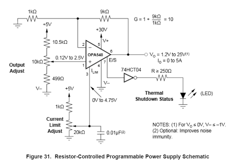
Q: Can the module amplify square wave or pulse? What is the module bandwidth? A: The module can amplify low-frequency square waves or pulses. Because it is an audio amplifier, the total bandwidth is not high. Signals within 100K can be amplified. The module is compatible with DC input. This is the over priced one with best Q/A https://www.amazon.com/operational-amplifier-current-continuous-voltage/dp/B07D8V1YBG/ref=sr_1_18?dchild=1&keywords=opa548&link_code=qs&qid=1605968887&sourceid=Mozilla-search&sr=8-18&tag=mozilla-20 The best price is 57.80$ Amazon.com - actually it's 35.60$ plus 5$ s/h on Ebay
-
The OPA548 op amp looks promising. It has up to 5 amperes output into 4 ohms or better. It can be bought in a complete amplifier see OPA348 on Ebay or Amazon.com just search for OPA548. The data sheet is here: https://www.ti.com/lit/ds/symlink/opa548.pdf As the amp can be used in a dc pwoer supply makes it look useful. If you have an Amazon account you can ask about the complete amplifier low frequency range else I can.
-
See the LM3886T at: https://www.alldatasheet.com/datasheet-pdf/pdf/8893/NSC/LM3886T.html?link=https%3A%2F%2Fwww.alldatasheet.com%2Fdatasheet-pdf%2Fpdf%2F8893%2FNSC%2FLM3886T.html It has a sample circuit with no capacitors in the pdf file. Also this amp board maybe useful, what ever "Pure DC Mono Power AMP Amplifier Board" means. It uses the LM3886T chip also: https://www.ebay.com/itm/LM3886T-x3-Parallel-150W-4-8-Assembly-Pure-DC-Mono-Power-AMP-Amplifier-Board/113895598886?_trkparms=aid%3D1110006%26algo%3DHOMESPLICE.SIM%26ao%3D1%26asc%3D225086%26meid%3D999c10d87a084a45a12ccb2f6e019c74%26pid%3D100005%26rk%3D2%26rkt%3D12%26mehot%3Dco%26sd%3D113918167015%26itm%3D113895598886%26pmt%3D1%26noa%3D0%26pg%3D2047675%26algv%3DSimplAMLv5PairwiseWebWithBBEV2bDemotionHighArwV3%26brand%3DUnbranded&_trksid=p2047675.c100005.m1851
-
Integrated circuits connectivity in Printed circuit board.
HarryA replied to prashantakerkar's topic in Electronics chit chat
I am not to sure what your question is. Are you asking can IC by its self, not in a package, be connected to a circuit on a PCB? Yes but it would need power and ground, etc connections also. An IC in a package like a DIP can. For example in the CDI (capacitor discharge ignition) circuit,that I am currently working on, the optoisolator (yellow) has the transistor directly connected to another device (MOSFET) on a another PCB.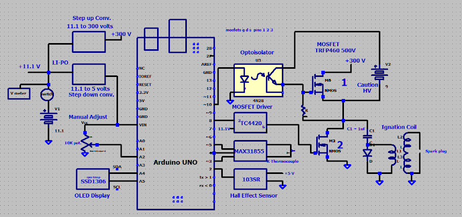
-
Also sounding proofing outside going doors and windows with heavy fabric is said to help. Plus having sound absorbing rugs and wall hangs reduces the unwelcomed sounds. I see one cannot edit previous postings.
-
Some years ago there was research on noise suppression by picking up a noise and playing it back 180 degrees out of phase. If you played a sound through two speakers connected out of phase, that is so when one cone came out while the other went in, would they tend to cancel? Thus creating a small cone of silence.
-
My guess would be that D!! and C7 are to suppress superfluous outputs on at the power outputs. D10 is part of the biasing for Q2 transistor? Member audioguru is far more knowledgeable of this circuit than I; hopefully he will come by and give an expert input.
-
I see little or no difference using Firefox, Opera, or Edge. I am thinking that it is my monitor. Watching to many "Extra History" videos on YouTube.com is wearing out the pixels 📺 Thanks for trying.
-
The font: "The font:" above is much lighter than the uploaded example. I could not see how to continue with the next image so I am here. I am using an HP x20LED; I can not get to the model number. Lets see what others say. For login one does not see the "Display Name" nor the "password" text. Perhaps removing the dead space above it would help?


-
Is it me or is the forum running out of toner? The font seems to be getting lighter over time. I can not adjust the browser to improve it. Also at login there is no physical response; the login area is down below the screen so one thinks nothing happened. Just trying to be helpful 😀
-
Although it is for the Arduino there is a library plus others here that maybe helpful for you to look over: https://github.com/deskwizard/TDA7418_arduino scroll down to see the implemented functions.
-
What are you connecting the PCF8575 to? You most likely need to include some type of library.
-
You can find some information on the sleeve balum that maybe helpful here: https://en.wikipedia.org/wiki/Dipole_antenna
-
ZY12PDN USB C 3S 12V Li Ion Battery Charger
HarryA replied to George R's topic in Electronic Projects Design/Ideas
I would think you need a power supply that is USB C compatible and supplies 15 volts like this one perhaps: https://www.amazon.com/ZMI-zPower-Turbo-Power-Adapter/dp/B07D64QLQ1/ref=sxin_10?ascsubtag=amzn1.osa.36fe220c-4964-4c9f-ae33-99b6c0c7c1df.ATVPDKIKX0DER.en_US&creativeASIN=B07D64QLQ1&crid=22R39DEACHL6V&cv_ct_cx=usb+c+wall+charger&cv_ct_id=amzn1.osa.36fe220c-4964-4c9f-ae33-99b6c0c7c1df.ATVPDKIKX0DER.en_US&cv_ct_pg=search&cv_ct_wn=osp-single-source-gl-ranking&dchild=1&keywords=usb+c+wall+charger&linkCode=oas&pd_rd_i=B07D64QLQ1&pd_rd_r=469feb9c-4fd4-4a62-9cee-bd7d3d9bc4b1&pd_rd_w=XpVfQ&pd_rd_wg=6mOQo&pf_rd_p=26c7e498-3189-4918-a321-ec25e32964ce&pf_rd_r=M6B5K23BD7AP9JZRKZ2Q&qid=1602096804&sprefix=USB+-C+charger%2Caps%2C234&sr=1-1-d9dc7690-f7e1-44eb-ad06-aebbef559a37&tag=thewire06oa-20 Plus a charger that has connections for balenced charging: https://www.amazon.com/11-1V-Balance-Lithium-Battery-Protection/dp/B07JMY631D/ref=sr_1_27?dchild=1&keywords=balanced+li+ion+3s+charger&qid=1602101378&sr=8-27 You can program the ZY12PDN to default to 15 volts instead of 5 volts. https://www.youtube.com/watch?v=aIHj3qMRqqE I never found a ZY12PDN datasheet. -
I would disconnect one end of R35 and see if that fixes the problem or just replace it. It maybe breaking down under the higher voltage?
-
https://www.manualslib.com/manual/119606/Panasonic-Sc-Dm3.html#manual
-
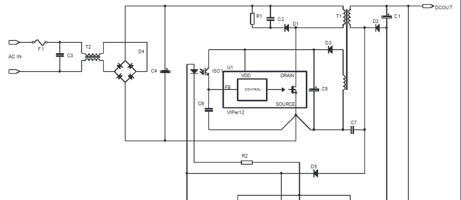
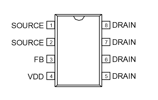
If you compare your board with the one on Ebay that one looks like the better board. You may gain some insight by comparing the P6? on your board with the three in the schematic and see if it connects the same as one of them. This is the schematic of the Viber12a in a battery charger.