HarryA
-
Posts
451 -
Joined
-
Last visited
-
Days Won
23
Content Type
Profiles
Forums
Events
Everything posted by HarryA
-

Newbie needs advice on making continuity LED box.
HarryA replied to Paul R.'s topic in Electronic Projects Design/Ideas
You could use an Arduino Mega 2560 as it has enough digital input/output pins for your 28 connections. Other micro-controllers may work but I only know the Arduino controllers. Do you need more than a simple one line display? "Yup pin 13 is okay" -
The D13005MD relates to the 3DD13005MD if that is any help. One would want to compare the two data sheets. It is not very likely one would have such a high power and high voltage transistor in ones stock. see: https://www.amazon.com/Generic-10PCS-D13005MD-3DD13005MD-TO220/dp/B0BRV663LX/ref=sr_1_37?keywords=d13005md&link_code=qs&qid=1684517602&sourceid=Mozilla-search&sr=8-37
-
Simple Audio sensor board connection to a speaker
HarryA replied to drmina2023's topic in Electronic Projects Design/Ideas
Just for you, anyone else there would be a fee😏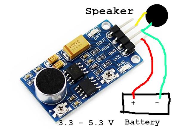
-
Simple Audio sensor board connection to a speaker
HarryA replied to drmina2023's topic in Electronic Projects Design/Ideas
No, just simply add a capacitor to the AOUT terminal ahead of the speaker from your board. Can you trace pin 5 of the LM386 directly to the AOUT terminal ? There may or may not be a small capacitor and resistor connected to pin 5 also. UPDATE: It look like the board already has an output capacitor. The yellow 227C is a 220 microfarad capacitor. So you do not need to add one. see: https://www.ebay.com/itm/391354402991?mkevt=1&mkcid=1&mkrid=711-53200-19255-0&campid=5338766894&toolid=20006& Just connect your speaker to the output terminals. -
Simple Audio sensor board connection to a speaker
HarryA replied to drmina2023's topic in Electronic Projects Design/Ideas
It looks like the unit you have is designed to work with a high impedance load like the input to the Arduino. Typically for a LM386 driving a 8 ohm speaker a 220 to 250 microfarad capacitor is used with the negative lead to the speaker. Try adding one to your unit. see the circuits here: https://www.ti.com/lit/ds/symlink/lm386.pdf?ts=1684218564218&ref_url=https%3A%2F%2Fwww.ti.com%2Fproduct%2FLM386 -
Perhaps you could get information from dioo via email. https://www.dioo.com/#/ProductsDetail?id=889
-
You could check the voltage output of the power supply before and after you have a problem with the unit. That would tell you if it is the power supply or not.
-
It is difficult to help you with no circuit diagram or photographys. Such problems are often thermal in nature. Something supplying current to the relay over heats and shut down perhaps. "Sometimes when turning on USB memory, or as the selected player plays. " Does that block it or unblock it?
-
What are the status attributes of a transformer other than temperature?
-
See: https://en.wikipedia.org/wiki/USB Be sure to look through the references at the end of the article.
-
Grounding issue with a turntable. House wiring? Ground loop?
HarryA replied to reeldeal67's topic in Electronics chit chat
Also see: What is a turntable ground cable -
Grounding issue with a turntable. House wiring? Ground loop?
HarryA replied to reeldeal67's topic in Electronics chit chat
Does the turntable have electronics in it; preamplifier and power supply perhaps? The capacitors in older electronics often go bad with age. see: https://en.wikipedia.org/wiki/Ground_loop_(electricity) note the section: "In low frequency audio and instrumentation systems" and the note near the bottom of the article. -
As gamer87 you have quite a reputation on the maker.pro forum. They lock the door as soon as they see you coming! They have no sense of humor over there.
-
Assistance with the voice changer using AP8072 IC
HarryA replied to Electronically curious's topic in Projects Q/A
In circuit 2 for the RTS0072 note they have an RC sub-circuit at pins 1 and 2, I would try that. Also note at pin 16 there is a resistor Rb to prevent pin 16 being pulled to ground. Perhaps required? Note it uses a 4.3 volt Zener; it must work okay with that voltage. -
I found the forum cookies were blocked on my end. I had thought I had removed the URL from about 20 or so sites I have blocked from setting cookies. Thanks for looking on you end.
-
When I try to login with my desktop computer I get this error code. Forum is unhappy with my desktop computer. I can login via my laptop okay. [contact us] does not work also - can not enter a message.
-
Assistance with the voice changer using AP8072 IC
HarryA replied to Electronically curious's topic in Projects Q/A
I would work on the voltage first. Although the specs, say 3.0V ∼ 5.0V for the RTS0072 ,there must be problem somewhere. The condenser mic. should not be drawing any current, try disconnecting it then recheck the voltage. Pop out the RTS0072 also. Specs. for the chip are here (see the second circuit which is like the one you are using): https://www.experimentalistsanonymous.com/diy/Datasheets/RTS0072.pdf -
Assistance with the voice changer using AP8072 IC
HarryA replied to Electronically curious's topic in Projects Q/A
The 1.69 volts at pins 11 & 12 suggest the Zener diode is in the wrong orientation. The 1.69 volts is the forward voltage not the reverse voltage of 4.7 volts you are looking for. If not try popping out the RTS0072 and recheck the voltage, perhaps it is shorted. -
Assistance with the voice changer using AP8072 IC
HarryA replied to Electronically curious's topic in Projects Q/A
I looked at your photo in photoshop where I could enlarge it, looks okay from what I can see of it. Check the voltage at the speaker and pin 6 of the LM386 for the 6 volts. Also check the voltages at the mic. and pins 11 & 12 at the RTS0072 for the 4.7 volts off the Zener diode. It is best to check voltages at the IC pins if you can. Also you could in similar manner check the ground connections with the meter. Could be a bad RS0072 ? -
Assistance with the voice changer using AP8072 IC
HarryA replied to Electronically curious's topic in Projects Q/A
Without a schematic of your circuit and a closeup photo of your circuit it is not possible to help you. -
Power Supply without "Power Saving Mode" -Seeking Advice on
HarryA replied to AJJJR's topic in Power Electronics
There are two types of USB power suppliers; the USB power supply and the USB power supply charger. It appears you are using the charger. Consider using a USB hub connected to the charger then connect your led/motion detector plus a simple LED device. The LED device would have a constant drain to keep the charger active? see for example(18ma). https://www.amazon.com/dp/B07RR3FQWF/ref=sspa_dk_detail_0?pd_rd_i=B07RR3FQWF&pd_rd_w=945qJ&content-id=amzn1.sym.0d1092dc-81bb-493f-8769-d5c802257e94&pf -
PROJECT to replace a MMBT3904 in a Lenovo G710
HarryA replied to crystallin's topic in Electronics chit chat
Comparing the two data sheets they appear to be nearly identical. the MMBT3904's higher current rating may make it last longer. -
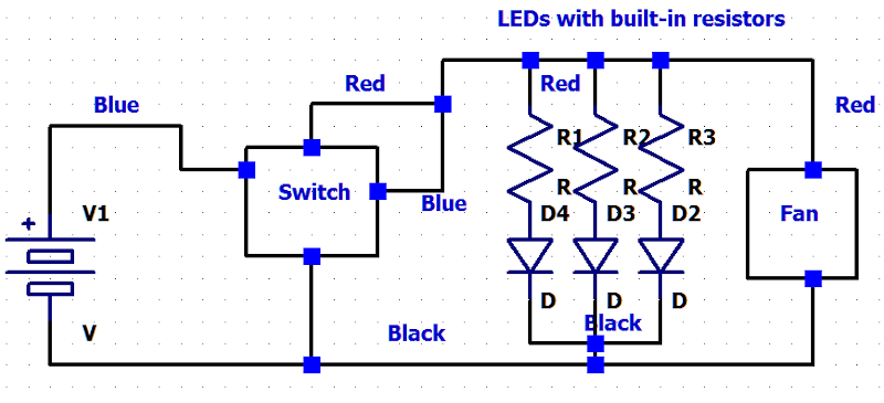
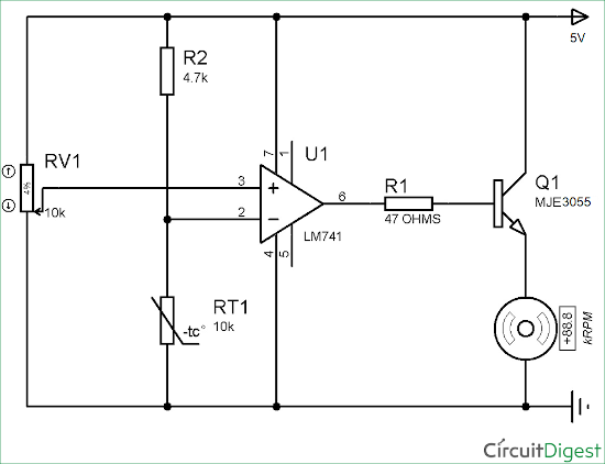
Here is a circuit that may work for you. I have a 10k thermistor and a MJE3055. I could try it on a breadboard if you like; converting it to 12v.
-
That is most likely an internal factory number. Remember they do not want you to repair them but to buy new ones. There are a number of videos on youtube in regard to chargers. Search on " Black&Decker 18V Li-ion charger " for example: https://www.youtube.com/watch?v=c-pTziUV1as
-
I believe this is what you need: push botton switch.asc push botton sw.xcf