

HarryA
-
Posts
451 -
Joined
-
Last visited
-
Days Won
23
Content Type
Profiles
Forums
Events
Everything posted by HarryA
-
There are devices similar to what you want on the market. This one has 5 minute delay. Perhaps if you poke around on ebay or amazon you could find a 10 minute one. https://www.ebay.com/itm/293677138457?_trkparms=amclksrc%3DITM%26aid%3D1110006%26algo%3DHOMESPLICE.SIM Else if you want to roll your own we could look at how to do.
-

Project For Power Consumption Parameters Display on OLED
HarryA replied to Keonte45's topic in Power Electronics
Are you looking to emulate one of these? https://www.amazon.com/s?k=measure+appliance+energy+use+with+a+plug-in+power+meter&crid=3QLC3ECDYF6C1&sprefix You asked this question July 8 on eepower.com and never folowed up on their question to you. Are working for pcbway.com ? -
From back in the old days: https://web.archive.org/web/20070926045222/http://www.electronics-lab.com/forum/index.php
-
That is not much information to go by. Perhaps you could use a MC1455/555 as a monostable employed as a switch; it has a rise time of 100ns. Plus a ZVNL120A N-CHANNEL ENHANCEMENT MODE VERTICAL DMOS FET it is good to 200v. It has a rise time of 8ns.
-
I am confused with the two SIDACs (Silicon Diode for Alternating Current) in series. They are rated 220-250 volts switching each. 240 mains voltages would be in the order of 340*1,4 or 480 volts peak. About the same as the two SIDACs; not much to switch with? "These tasks of the starter are taken over by two 135 V sidac (or a single 270 V one). The starting voltage is thus 270 V, Which is below the peak value of the mains (about 340 V), but higher than the working voltage of a 20-40 W neon tube." see: https://circuit-diagramz.com/sidac-neon-tube-starter/ I will look at the circuit some more.
-
need help electronic/relay problem phone horn
HarryA replied to georgebaker's topic in Electronic Projects Design/Ideas
Search on the internet for "need help electronic/relay problem phone horn". As he posted this on 5 or 6 other forums you may find useful information there. -
Your BMS (HW-391): Product Model: HW-391 Charging Voltage: DC 8.4-9V Version: Balance Constant Discharge Current: Max 20A (If the heat dissipation environment is not good, please reduce the use of load current) Constant charging current: Max 10A) https://makerselectronics.com/product/lithium-battery-charger-protection-module-bms-2s-20a-7-4v-balanced-version Some say a BMS (battery management system) is not a charger but there seems to be come confusion here. One thing that is not clear is what is the nature of your 8.4 volt power supply. Also is the BMS preventing the battieries from discharging below the allowable voltage level for a li-ion battery.
-
If you use a 12v and 3 ampere charger that would require a little over 36 watts. A 12v and 1 ampere charger would be about 12+ watts. That would be less load on the power supply. Assuming the power supply is the limiting factor here. The slower charge rate would not be a problem if you do not have power outages more than once a day?
-
If you do not see the 8.4 volts at the 5v to 12v converter it suggest that the power supply has gone into a thermal overload state. Perhaps due to the drain from the charger. Switching it off resets it perhaps.
-
The meter needs calibration. My AstroAl M2KOR has for DC current: accuracy +/- ( 1.2% rdg + 5 dgts). Whatever that means. Also "when large currents are measured the continuous measurement should not exceed 15 seconds".
-
My old Scope multimeter has a 0.01 ohm shunt resistor in the 10 ampere circuit going by the schematic. That is not much of an intrusion into a circuit. I would think the analog meter is most likely the most accurate meter in your case. What does the clamp on meter give you? Knowing the on and off time of the pulses one could calculate the peak current from the one ampere reading?
-
control circuit for solar panel tracker
HarryA replied to Redge's topic in Electronic Projects Design/Ideas
This is easier to do today with microcontollers like the Arduino UNO for example. Else you can fabricate it from logic circuits using a number of timers like the MC1455 (a newer NE555). I can help you with either approach but recommend the microcontroller. If you are not familiar with them it would be a good project to learn on. You will notice there are a lot of solar trackers on Ebay for less cost then to make one. -
triac firing using pnp transistor
HarryA replied to petercl14's topic in Electronic Projects Design/Ideas
"none of those circuits are the one I posted with the pnp transistor connected to the gate. " How about this one? With thanks to homemade-circuits.com In LTspice simulation all I ever get is the TRIAC off or fully on. As there is no phase control, because there is no relationship between the transistor and the AC supply. It simple allows the TRIAC to conduct or not. In theory you can connect the transistor to your microcontroller and use the circuit as a replacement for a mechanical relay. There is a problem with the lack of isolation from the ac mains. That is why optical isolators are used.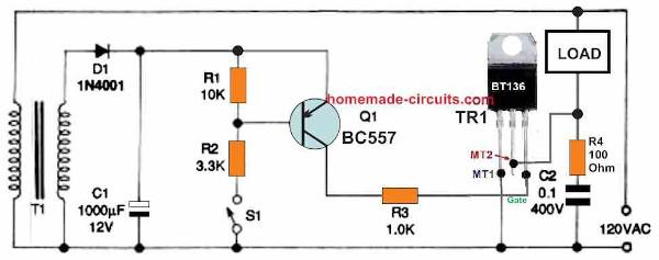
-
triac firing using pnp transistor
HarryA replied to petercl14's topic in Electronic Projects Design/Ideas
See figure 5 here for similar circuit: https://www.homemade-circuits.com/simple-triac-triggering-circuits-explained/ -
triac firing using pnp transistor
HarryA replied to petercl14's topic in Electronic Projects Design/Ideas
You are starting with a very primitive circuit. There are many complete TRIAC circuits to be had via internet search. LTspice does not have a TRIAC model because Analog does not manufacture them. If you search on TRIAC on Youtube.com you will find numerous videos on the subject. This one has information on finding and download a TRIAC model for LTspice. https://www.youtube.com/watch?v=lRz1gql-BWw Expand the 'show more'. Also missing are the requirements for your circuit; 1 amp or a 100amp?.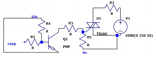
-
There are numerous videos on Youtube on uploading to the Atmega328. This video has three ways to up load to the Atmegs328. Two methods use a UNO and one using the FTDI. The second method using the UNO gives one insight into how the loading process works. https://www.youtube.com/watch?v=Sww1mek5rHU Also this one uses the FTDI and uploads as an UNO board (if I put the url in here even as text the stupid video gets inserted here and I see no way to delete it). Search on " 1-Day Project: Build Your Own Arduino UNO for $5 " on Youtube. Some of these may give you insight to your problem. The circuit from the article may not be the best. Seeing what circuits they use maybe helpful. I am having a $%^*& time with this post! This my third attempt.
-
It is not clear to me what you are trying to do. You say " I have been using the nano board for a long time now ". So you must have loaded programs into it? The Nano uses the ATmega328 the same AVR as the Uno. "Tried picking Uno board in tools menu". ? The Nano board is listed in the list of boards in the IDE is it not? https://docs.arduino.cc/hardware/nano "follow the links to the page that starts with; " Installing the AVR core The classic Arduino boards, including the favorites UNO, Nano and Mega, requires the AVR core to be installed to compile and upload sketches to your board. Fortunately, the classic IDE comes with the AVR core already pre-installed. This means that we only need to download and install the editor to start using our Arduino products.
-
https://components101.com/sites/default/files/component_datasheet/AT89C51.pdf
-
see recent post https://www.electronics-lab.com/community/index.php?/topic/48683-programming-the-atmega-328p-microcontroller-previous-article-on-this-subject/#comment-166370 I do not know anything about the Jaycar; sorry can not help you there. I just use the Arduino IDE. By the way there is a new version of the IDE; version 2.0 For those folks that use the IDE.
-
If you look in the IDE at [tools] -> boards you will see the Nano and the Duemilanove. You will not see the port listed until you select the board and have a board or adapter connected. The Meg2560 has a different AVR microcontroller; an ATmega2560. If you search on Youtube for the FT232RL (the USB to serial/TTL Adapter) you will find numerous videos. Speaking of ports, the current port is shown in the IDE in [Tools] also in the Preferences file. The Preferences file can be found [file] -> Preferences. That brings up a pop up window containing the path to the file. Near the bottom of the file can be seen the comport listed in two places. Also in the Device Manager it is listed under Ports(COM & LPT). Device Manager is via [Windows] + [x]. Sometimes you can edit the Preferences file to bring the comport inline with the device port iIf the IDE gets confused. You may know this but others may not. (I screwed up the fonts by cut and past again)
-
"What is the board type?" Note: when programming the Atmega328p MCU using the Arduino IDE, the matching board type you have to select is the “Arduino Duemilanove or Nano w/ ATmega328” board. :What port would this be? I take it to be the comport related to the IDE and PC. Shown in [tools] menu of the IDE. Connected to pins: 1,2,& 3 on the ATmega32 chip. https://www.electronics-lab.com/wp-content/uploads/2018/09/programming-Uno-on-breadboard.png For others the article is here: https://www.electronics-lab.com/project/programming-atmega328p-microcontroller-with-arduino-ide/
-
Buck Converter Design
HarryA replied to ElectronicsLabUser's topic in Electronic Projects Design/Ideas
In LTspice on selecting components open the directory [Power Products] in the listing find LTC3705 when you click on it you will see "Open this macromodel's example circuit" that will display the circuit. You can select RUN and the output display will come up. You can poke around the circuit with the "red probe" and see the various wave forms are there. You may know this already but other reads may not. Perhaps if you click on some other types there you will find more converters of interest; as it displays a brief description of each. The Analog site listed above is is busted. I got in once but never again. But if you search on LTC3703 off that page you will get some links that look like they may be helpful. This link seems to work. Gets you to where you can enter you requirements. https://www.analog.com/en/product-category/step-down-buck-regulators.html -
" {Bluetooth} It is mainly used as an alternative to wire connections, to exchange files between nearby portable devices and connect cell phones and music players with wireless headphones." You may violate some code of ethics by connecting two Bluetooth devices together by wire. https://en.wikipedia.org/wiki/Bluetooth One needs to know what type of devices you are using to have any idea how to interconnect them. If they have speakers or phone connections that would be a start. Class 1 Bluetooth devices have a range of about 100 meters.
-
Buck Converter Design
HarryA replied to ElectronicsLabUser's topic in Electronic Projects Design/Ideas
As this chip is made by Analog and Analog owns LTspice simulator the circuit appears in the simulator and can be explored there. The circuit there is slightly different. Note it uses the FDS6680A mosfets. If you want 10 amperes make sure the mosfets can handle the current. Go here and put in your requirements then you will see some 10 ampere chips: https://www.analog.com/en/parametricsearch/11491#/p5573=min|24&p5574=100|max&p5347=min|12&p5357=12|max&p5349=10|240&qsfv=vinmin|24_vinmax|100_vout|12_iout|10&p5362=Buck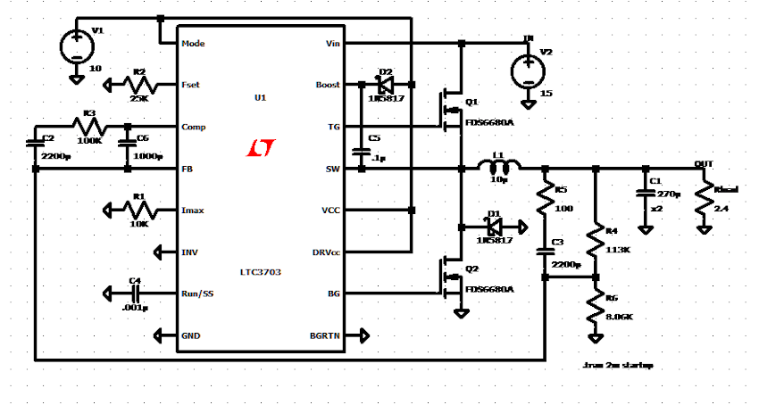
-
Buck Converter Design
HarryA replied to ElectronicsLabUser's topic in Electronic Projects Design/Ideas
There is a lot to designing a dc to dc buck converter. For example see: https://www.maximintegrated.com/en/design/technical-documents/tutorials/2/2031.html You can buy one for far less than the cost of the parts to build one. See: https://www.amazon.com/Aceirmc-Converter-Adjustable-Regulator-Protection/dp/B0823MM1DV/ref=sr_1_6?crid=1AB7YZ4O9O8B0 You may find complete circuits on the internet. The inductor is the tricky part . What to use as a core and how to wind it for 20 amperes.
