HarryA
-
Posts
451 -
Joined
-
Last visited
-
Days Won
23
Content Type
Profiles
Forums
Events
Everything posted by HarryA
-
If it is a 120 volt Cuisinart blender then you can get one here: They ship world wide. Else search for "1 uf 250vac capacitor" https://www.ebay.com/itm/281873849657 That is a horrible url !
-
You have asked this question on 3 or 4 other forums and got labeled on this one as a troll: https://www.electro-tech-online.com/threads/question-nor-flash-memory.161524/
-
The problem is what will read a flash drive 20 years from now? The same for data storage devices like CD's, hard drives, and tapes. Perhaps the best solution is to transfer the data to new media every few years. Also it is a good idea to store copies off site (at friend's home for example) in case a Chinese spent rocket lands on your house. Or print on papyrus and seal in clay jars 😀
-
No, the information is not readily available. From page 29 section 7.3.2 "Storage condition" in: http://www.epcos.de/blob/185386/download/4/pdf-generaltechnicalinformation.pdf "If not otherwise specified, our aluminum electrolytic capacitors can be stored voltage-free at above stated conditions (from +5°Cto+35°C, relative humidity≤75%) for at least two years; capacitors of the SIKOREL series can be stored for as long as 15 years under these conditions. Within these storage periods the capacitors can be operated at their rated voltage directly after being taken out of storage. It is recommended to mount the capacitors in the application within one year of delivery in order to prevent any problems with solder ability of capacitors on PC " There is some information at: https://en.wikipedia.org/wiki/Electrolytic_capacitor#Reliability_(failure_rate)
-
I take it if one is not going to use something often one should power in up say once a year or so. The question is if one is not going to use something often enough to keep the electrolytic capacitors refreshed why keep it at all? I keep my old audio amplifier thinking I will use but I may never use it.
-
Folks that restore old radios say do not power them up until replacing the capacitors. It is difficult to find information on failing due to disuse. Wikipedia has some information related to storage. See "Performance after storage" here: https://en.wikipedia.org/wiki/Electrolytic_capacitor#Operational_characteristics Years ago, okay many years ago when I was in HS, I used to repair radios and bw televisions. I repaired a radio that a mouse had chewed into a wax coated capacitor.
-
Modern aluminum electrolytic capacitors have longer shelf lives then the old ones, usually around 2 years. Perhaps powering up old equipment a couple of times a year would be sufficient. Once a month is perhaps unnecessary. I have never found any good information on that subject. I have an old audio amplifier I power up a couple of times a year. I keep thinking someday I will use it - perhaps.
-
There are three things to consider. First the voltage from the charger is higher than the batteries voltage in order to charge the batteries. Second the current supplied by the charger is most likely much smaller than the current supplied to the unit by the batteries during operation. Also there is a var (volt-ampere reactive) which is an back emf from the coil as the field collapses. This maybe more then the charger can handle. Shavers typically draw 10 to 15 watts off the mains and some higher.
-
I would think that using the devices, as you suggest, once a month would be a good idea. Also you could do a quick test on the capacitors if you have not used the device in some time. I often check the capacitor with a multi-meter using the ohmmeter range without disconnecting it. The reading will start low then rise as the capacitor charges indicates a good capacitor. If this fails I disconnect one lead and try again. If the reading stays low it could be shorted. If no capacitance it will often just show a high reading. see: https://www.wikihow.com/Test-a-Capacitor If you doing many capacitors perhaps a tester would be worth the monies: https://www.amazon.com/HiLetgo-Multifunctional-Capacitor-component-Backlight/dp/B01MYU0QI3/ref=sr_1_10?dchild=1&keywords=tester+electrolytic+capacitor+tester&qid=1619267945&sr=8-10
-
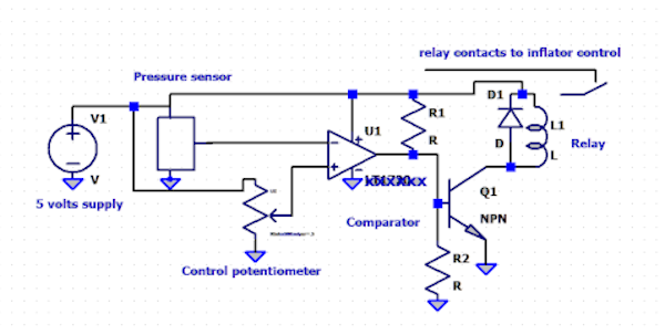
Are you looking for a circuit like this? This is not a finished circuit it is just an example.
-
Sorry but you must tell us what you have now to work with and what are your goals. Do you have a sensor or need to find one to buy? What type of air pump or inflator do you have or need? If you need a sensor this company has 1 - 5 volts ones that you could subtract 0.5 volts from as an example. https://www.sensorsone.com/10bar-150psi-0-10v-0-5v-1-5v-pressure-sensors/
-
"Hi, I need a digital car blower circuit with the ability to adjust the pressure with a pressure sensor 10 times 5 volts with an output of 0.5 to 4.5 volts." Sorry Google does not translate Persian into English well. What is "a pressure sensor 10 times 5 volts" ? با عرض پوزش ، فارسی را به انگلیسی ترجمه نمی کند. "سنسور فشار 10 برابر 5 ولت" چیست؟ You may find this translator helpful: به نظر شما این مترجم مفید است https://translate.google.com/
-
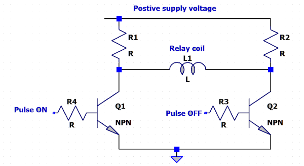
Step 1: Are you committed to using to using the TC4420 and 40193? Consider using a circuit like the one below. The direction of current flow through the relay coil depends on which transistor is on. Also if you do not have the relays yet these may simplify your design: https://www.amazon.com/SMAKN-Trigger-Switch-Latching-controlled/dp/B01CN7V0F6/ref=sr_1_20?dchild=1&keywords=latching+relay&qid=1617978673&sr=8-20 What are you using of inputs to the circuit?
-
There are a couple of videos on Youtube you may find helpful. The first one uses a socket with colored wires while the second one shows the terminals on the back of the switch. In the first one he connects directly to 12 volts while in the second one he claims the LED is 3 to 6 volts and uses a resistor to connect to 12 volts. If you need help connecting to the board I will look at its specifications. https://www.youtube.com/watch?v=nlPj0VL_bGU https://www.youtube.com/watch?v=zd3n8pYFx1g
-
That is a complex beast! Given: "Each LED output can be off or on (no PWM control), or set at its individual PWM controller value. The LED output driver is programmed to be either open-drain with a 25 mA current sink capability at 5 V or totem pole with a 25mA sink, 10 mA source capability at 5 V." If you are using the PWM control the meter would not show the peak currents to the LEDs. Other then that it is difficult to help troubleshoot something that requires programming.
-
As the TC4420 accepts logic level inputs and the 40193 output is a logic level why is anything needed between them? Also both only require a single voltage supply (Vdd) for the circuit shown a dual supply would not be required. There are single Vdd supply op amps if you need one. I have a circuit that uses a TC4420 driven directly via a Arduino Uno output.
-
Are pinball schematics any different than electronic schematics? https://learn.sparkfun.com/tutorials/how-to-read-a-schematic/all
-
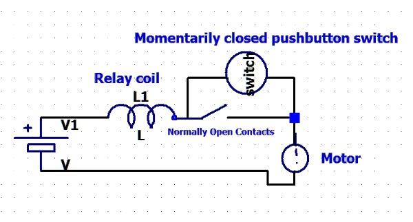
I gather you are looking for a circuit like this one. Do you have any idea what the currents are? Perhaps one could key off the change in voltage at the battery; low voltage turns a transistor on to power a relay. Edited: The circuit needs a momentarily open push button switch between the battery and the relay coil to switch if off.
-
There is something about pulse transformers dealing with the pulse width. If the input pulse width is two short the current never has time to build up completely do to the lagging current in an inductor/coil. That would look like an impedance mismatch also. If the pulse is to wide current is wasted when the coil is fully energized. For example see https://www.youtube.com/watch?v=vvXbTIqBY4o
-
Yes you can use a battery as long as it is 6.0 volts. How long it will last will depend on how much current the camera draws. If you are using 4 AA batteries there is good information here: https://www.powerstream.com/AA-tests.htm
-
Your getting just 3 volts suggest an impedance mismatch between the transformer and the cell. In looking at using automobile ignition coils for high voltage I see a number of videos and articles where they get huge sparks from the coils that I can not get. I feel like you; where is the spark! I am thinking my coil is a dud! See for example: https://www.youtube.com/watch?v=PTt5sM3moqQ There are a number of similar videos there using ignition coils for high voltages.
-
We know the output voltage is related to the ratio of the number of turns. And the output current related to the inverse of the number of turns. The more voltage gives one more current at the primary so in an ideal transformer the power is the same on both sides of the transformer. But in a pulse transformer is it not the rate of change of current in the primary that gives rise to the change in magnetic flux that produces the voltage? I need to learn more about pulse transformers. I had in mind trying out different frequencies on the automobile coil/transformer but had a problem when I connect the second probe to the current monitoring resistor while the first probe was floating on the output of the coil. The 100 watt lamp when full brightness and it when down hill from there. I will continue later. Anyway I had put a voltage divider across the output of the auto. coil (a 1094k and a 9.84k) and got + and - 32.8 volts peaks on the scope at the 9.84k. I calculate the output voltage at +3679 volts and -3679 volts peaks. DUT device under test?
-
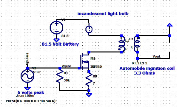
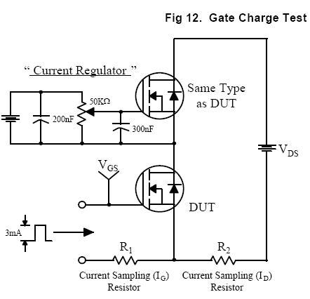
Using the 100 watt bulb and two different ignition coils this is what I got: AC Output(VOM) 1 meg load Input sig. 204 Hz Peak voltage across 7ohms coil type 67.4 v 6.0v 1.84 v std auto ignt. coil 159.8 v 9.68 v 5.44 v 17.4 v 8.0 4.0 - 4.2 v Capacitor discharge coil The std auto coil is a 12 volt and a few amperes coil. While for the CDI coil I am running it via discharging a 1 mfd capacitor charged to 350 volts in my experimental chain saw ignition system. So neither are designed for what you are doing. Speaking of coils/transformers Scherz and Monk have information on transformers in their "Practical Electronics for Inventors" you may check it out the next time you are in a book store. I think using a incandescent lamp (as a ballast resistor) and controlling the current via the input signal is useful but using a mosfet as current regulator maybe useful also. This regulator is from the IRF530 pdf sheet. I use a similar circuit in my ignition system floating a 9 volt battery at 350 volts. The 12 volts at the battery got cut off.
-
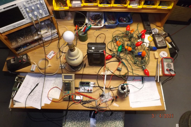
Don't laugh that is an emulation of your circuit. I was thinking that there is not enough load in the circuit with only the coil (the mosfets are acting like switches only off or on) so I started out with 7 watt incandescent lamps but could not get two mosfet to work so I switched to only one; that works well. In the photo at the lower right is an automobile ignition coil and the big black thing is an 80 volt battery (borrowed from my chainsaw). Working up to 13 bulbs (normally 7 watt bulbs) I got 0.571 ma through a 7 ohm resistor. Switching to a 100 watt bulb got 0.594 ma, the IRF530 got up to 32 degrees C. I do not have any IRF580's. The input signal is 6 volts peak. The 50k resistor is a pot. max'ed out. I turn the input up from low to high to prevent any inrush of current into the lamp(s), I do not know if that is necessary or not.