HarryA
-
Posts
451 -
Joined
-
Last visited
-
Days Won
23
Content Type
Profiles
Forums
Events
Everything posted by HarryA
-
I was using the fixed resistors as the simulator dos not have a concept of a potentiometer. Putting the 530 back in an using a combination of two resistors between 30k - 17k to 46k - 1k (where the lower value is to ground) I get good results with 40k - 7k and 30k - 17k but the peak current is 2 amperes for some reason. At 44k - 3k the current is 900ma but the output is down to 50v. I will continue looking at it. If you have a symmetrical pulse waveform say of 1 ampere I gather the rms value of the current is 1 * 0.707 and the rms voltage would be 100 * 0.707 so the equivalent power would be: 0.707 * 70.7 = 49.98 watts not the 100v * 1a = 100 watts of a continuous drain. So one may be able to run it above 1 ampere. ref: https://masteringelectronicsdesign.com/how-to-derive-the-rms-value-of-pulse-and-square-waveforms/
-
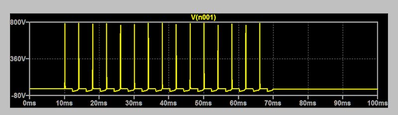
I would think you are not hitting it with enough current. Using a resistor instead of the IRF530 as it is faster to use rather then dorking around with two resistors to simulate a pot. I am using a input pulses that 2.5 ms on and 2.5 ms off at 6.8 volts peak No bifilar coil nor diode in the output: resistor current output capacitor output resistor output voltage 100 1A 1.058 nf 1.16 meg 720 volts 100 1A 0 1.16 1.05 kv 50 2A 1.058 nf. 1.16 1.0 kv 50 2A 0 1.16 1.2 kv The current being a symmetrical pulse(?) would be only be half of a continuous draw from the power supply.
-

Desing a regulated voltage source with a transistor and a zener
HarryA replied to Annie Fernández's topic in Projects Q/A
New section: For R1(max). Assuming a 8 volt transformer. Vin = 8.0 * 1.4 or 11.2 Taking the min and max to be plus or minus 10%. One would not need a voltage regulator if there where nothing to regulate. Vmin = (Vin - 10%*Vin) - (2 * voltage drop across the two diodes). Typically 0.7v each. And Vmax = Vin + 10%Vin - (2 * voltage drop). R1max = (Vmin - Vz)/(Izmin + Ib) Izmin is found from the zener data sheet; typically 10 ma. What happens at Vmax? R1max = (Vmax - Vz)/(Izmax + Ib) Where Izmax is the only unknown here. Izmax must be within the maximum current for the Zener. If that works out okay use R1max. For C1; using the equation from Scher & Monk's "Practical Electronics for Inventors" section 11.6. Vripple(rms) = 0.0024s * Il /Cf Where Il is the output current and the current through Iz plus Ib. Taking the Vripple = 100 mv or 0.10vrms = 0.0024 * Il / Cf Remember Cf is in farads and Il in amperes. You may expect Cf in the order of 1000uf. Use whatever Vripple you wish. Digital ICs need less than 0.25% * Vout but the zener does regulation also. If you wish I can run whatever values you come up with through the circuit simulator if you do not access to one. -
Desing a regulated voltage source with a transistor and a zener
HarryA replied to Annie Fernández's topic in Projects Q/A
Part one: Starting on the right: the load resistor minimum would be Ro = Vout/Iout. As the transistor is used as an emitter follower the output will be near a voltage gain of one. For the Zener diode and Vout of 6.0v you must allow for the voltage drop Vbe (Vb to Ve) of 0.6 to 0.7 volts. So Vz = Vout + 0.7 volts or a Zener with a voltage at or above wanted Vz. R1 supplies current to the base of the transistor and the Zener. The current input into the base of the transistor can be found using the hFE (the forward current transfer ratio) or current gain of the transistor. Ib * hFE = Io. hFE is in the order of 100 or so. So Ib = Io / hFE; thus Ib adds little to the current through R1. You can calculate the minimum value of R1 given the wattage of the Zener. Iz(max) = watts/Vz. A zener for this type of regulator could be 500 milliwatts. Then R1(min) = (Vin - Vz)/Iz the voltage drop across the resistor divide by the current through it. But what is Vin? Using my rule that the input voltage is 1.5 volts times the Vo or better. Picking a 8 volt transformer (for now). That gives a Vin of no more than 8 * 1.4 or 11.2 volts as the peak voltage. What is there a maximum value for R1? to be continued... -
In the simulator (with 100 ohms between the PSU and the coil and 1 ohm resistor in the source lead of the ITF840) the output is about 1.2kv peak with or without the 1.164 meg resistor. With the 1.058nF capacitor it drops to about 750v and with the 5.18nF it drops to about 450v. The current through the secondary coil is +29ma to -42ma peaks. The current through the primary is 0 to 1.8 amperes peak. This is with a 100 ohm resistor between the PSU and the coil. At the 1 ohm resistor in the source lead of the ITF840 it shows 1 ampere peaks. I found an ITF840 spice model. If you put a small resistor in the source lead of the IFR840 you could measure the voltage across it and see if the current is what you expect.
-
Can you measure the resistance of the cell? Possible it got comtaminated. Also knowing the size of the electrodes and their separation in water one could get a first order approximation of the cell's capacitance.
-
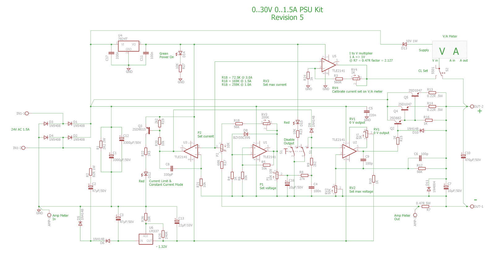
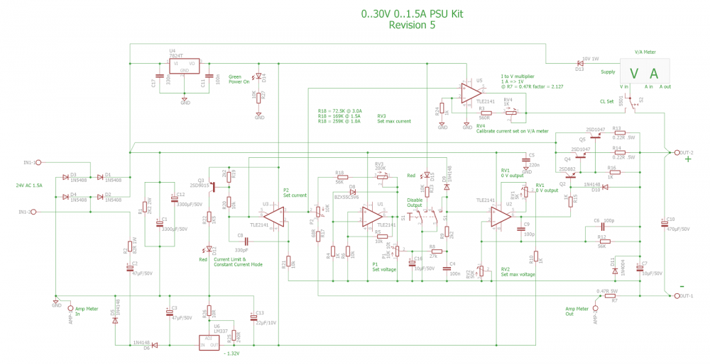
I must admit the more I look at the circuit the more confused I get. Why the negative rail connects to the TL081 is beyond me. Why it connects to the 30 v rail when it is only rated 18v max is a mystery to me also. Also there are many different up grades to the circuit I gather; for example I have this one I got from somewhere. Note the differences in connections to negative rail and a voltage regulator not the zener diode. Also if you search for "0-30 V PSU not workingy" on the internet you will find this PSU has been beaten to death numerous times on various forums including this one.
-
What happens when you connect the load? You may try to connect a small capacitor across the output if you have one that has the required voltage rating. The last trace maybe as good as you can get. I will try adding distributed capacitance to the windings to see if that produces similar results in the simulator.
-
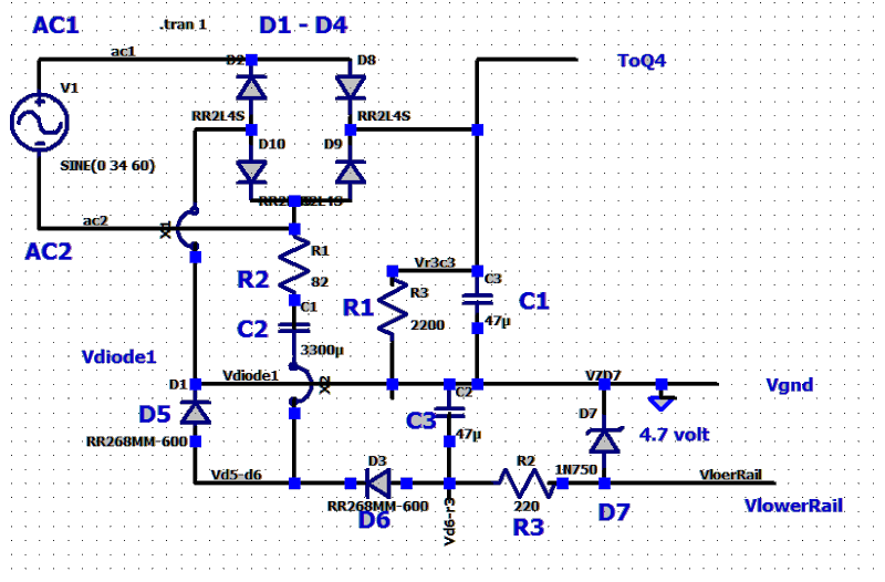
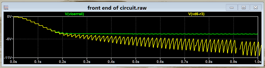
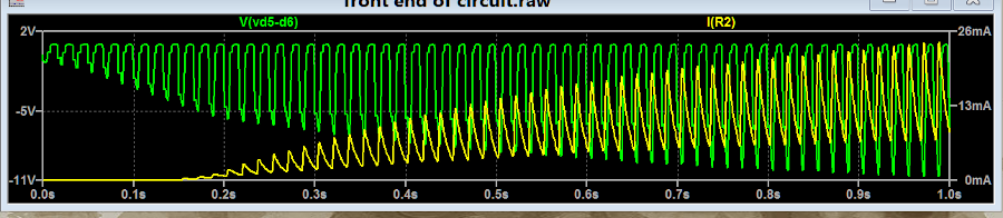
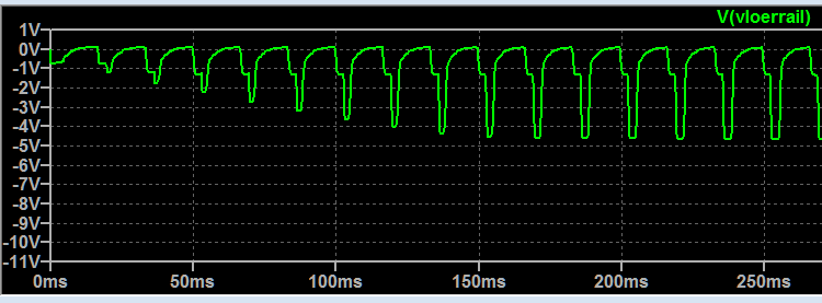
Putting just the front end into the simulator. The labels in large print map back to the schematic. Using a 4.7 volt zener simulator doesn't have a 5.1 zener. In these traces the green is the voltage on the negative rail and the yellow is between D6 and R3. In this one the green trace is between D5 and D6 while the yellow trace is the current through R2. And this one is with C3 disconnected. voltage at the negative rail.
-
What is a Nilma Radio? Are these band pass filters used in the antenna input used when selection one of two radio bands? If you have both types of inductor cores why not use them? As you are on the upper limit of the T37-2 cores and the T37-6 cores (lower limit) do not need to go below the upper limit of the T37-2 cores for the higher frequencies.
-
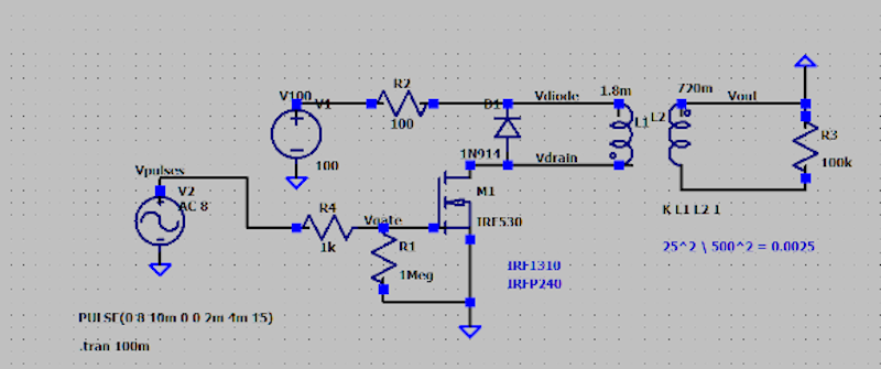
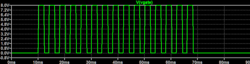
As a first try the circuit below has a transformer with the primary of 1.8mh and 0.1 ohm while the secondary is 720mh and 150 ohms. The inductance is related to the number of turns squared ratio: 25^2 to 500^2 = 625/250000 = 0.0025 thus ( 0.0025 * 720mh) = 1.8mh So your guess is a lot better than mine would be. For input the pulses are 2ms on and 2ms off for a period of 4ms. Amplitude is 8 volts. The out put would make a good TENs device for an elephant.
-
I set the browser to display the links in large bold fonts. As the first page is all links that did what I wanted to do.
-
What are you using for input pulses? Any idea what the inductance of the primary and secondary windings of the transformer are? Else does anyone have a good guess what they may be? I have never used inductors enough to get any concept of what transformer inductance like that would be. I can run the circuit in the simulator if you like.
-
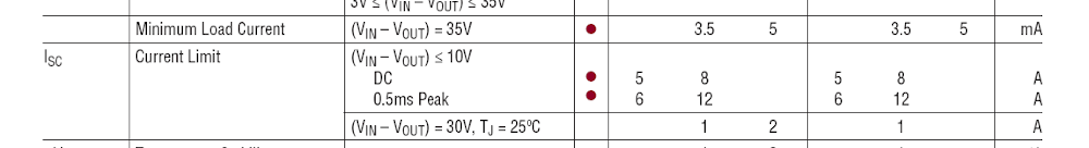
I believe you are correct. Yes they are beefy - see: https://www.ebay.com/itm/OHMITE-RHEOSTAT-100-OHMS-100-WATT-MODEL-K-STOCK-NO-0451/223494235238?hash=item34094b6466:g:MHYAAOSwJHhcwbwy You could consider using a 1 ampere fast blow fuse. Ideally one could put a second power mosfet at the output of the power supply and use that to control the current and control it via a potentiometer. What is 1 ampere when using a pulse amplifier? Is it the peak pulse current or would you have to integrate the sums of the currents? I would think it relates to the power dissipated by the power transistors in the power supply.
-
The codes most likely only have meaning to the manufacture of the circuit board they are on. Manufactures do not want customers to be able to repair their products rather them buy new ones. Can you find a schematic?
-
Bear in mind the headroom for the LM388 is 3 volts. The headroom voltage refers to the actual voltage drop across the regulator that must occur during operation. So that means that the most you can get out of the above circuit is 9 volts. Minus the drop across the 0.3 ohm resistor. You maybe better off using your one transistor circuit if you do not need the power/current for extended periods. If so perhaps there is a spice model for the IRFB4110? You could run it in the LTspice simulator and/or I could run it in the TINA-TI simulator. Also there may be a similar transistor that there is a spice model for; for simulation if you decide to go that way.
-
The max for the LM388 is 12 amperes: Look at the the Buck Converter here; one reviewer is pushing it to 25 amperes with a fan/blower cooling. https://www.amazon.com/Anmbest-Converter-Adjustable-Regulator-Protection/dp/B07R832BRX/ref=sr_1_41?crid=3ETDJKMX4K9ZO&dchild=1&keywords=dc+12v+converter+step+down+module&qid=1610919636&sprefix=dc+12v+step+down+converter+12v%2Caps%2C407&sr=8-41 I should get a kick-back from Amazon.com for all the times I reference them.😉
-
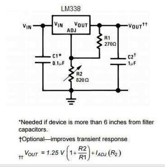
You do not need the bridge diode nor the 4700 mfd capacitor but keep the 0.1 mfd as it is typically in voltage regulators of that type. You may need heat sinks and heat sink compound; look up "lm388 pdf" files for more information. This illustration is set up for 5 volts:
-
It may work but as you say it is not very efficient. You can stack voltage regulators to get the current you need if you wish to roll our own. See the 4-20 volt 20 ampere circuit here: https://www.eleccircuit.com/high-power-supply-regulater-0-30v-20a-by-lm338/ Also you can buy a motor controller that may work for you - rated 30 amperes. With luck you may get one that works - read the reviews. https://www.amazon.com/RioRand-7-80V-Motor-Controller-Switch/dp/B071NQ5G71/ref=sr_1_4?dchild=1&keywords=adjustable+voltage+regulator&qid=1610728630&sr=8-4 Now I see " it is a DC Motor Speed Controller,Not a Voltage Controller "
-
There is a good write-up here that maybe helpfu- using the Knowles Electronics, Inc. EK23029 electret condenser microphone: http://oldbird.org/mike_home.htm Also see: https://en.wikipedia.org/wiki/Microphone#Application-specific_designs and https://www.allaboutbirds.org/news/capturing-natural-sounds/
-
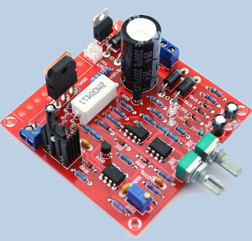
The best you can do is to start at the output transistors and work your way back through the circuit. It is impossible to diagnose homemade circuits at a distance as there are just to many places to go wrong. For others never build something you can buy cheaper. Get two at 8$ each - one for parts. https://www.ebay.com/itm/Stabilized-Continuous-Adjustable-DC-Regulated-Power-Supply-Kit-0-30V-2mA-3A-L/353345066780?hash=item524501d71c:g:JjsAAOSw~QteWLkt
-
To Calculate C when Vf, R, t and Vi are known; see https://hoven-in.appspot.com/Home/Blog/rc-discharge-calculator.html For R = 4 (0.004k) ohms, Vstart = 400v, Vend = 300v, and time = 15ms I got C = 13035 μF.
-
Detecting Resonance in an Electrolysis System
HarryA replied to Kerrowman's topic in Inventive/New Ideas
Also consider power oscillators. Like the royer oscillator used in induction furnaces. Your capacitor would be part of the oscillator circuit thus solves the resonance problem. I tried one in LTspice like the one in this link; got oscillations similar to your voltage and current display above. I could not find a Spice model for an avalanche diode so I used a low voltage zener for the BYV26E. Searching on "royer oscillator" brings up lots of hits. https://krishnamurthy1995.wordpress.com/2016/04/20/royer-oscillator-based-induction-heater/ -
Detecting Resonance in an Electrolysis System
HarryA replied to Kerrowman's topic in Inventive/New Ideas
I would think that the transformer would destroy the nature of the resonance circuit. Are you thinking that if you find the resonance frequency of the real circuit then as the water is consumed it would change the resonance frequency by the change in capacity of the cell/capacitor? You may wish to make sure that you are getting the results you expect by driving the circuit with a fixed frequency and seeing if you get any results at all. By the way there is an online signal generator that you can sweep your circuit with to find the resonance frequency and drive the pll for a first test perhaps. https://www.szynalski.com/tone-generator/ You can get the output through you pc's speaker output jack. -
Detecting Resonance in an Electrolysis System
HarryA replied to Kerrowman's topic in Inventive/New Ideas
I believe the only way one may detect resonance is with something that has a memory be it human or microcomputer. One needs to know that it is passing resonance peak and then backup. A microcomputer could store values and keep comparing the values until the current value is less then previous values. There are current detectors that encircle one lead that maybe less intrusive than a direct connection to the capacitor if you can find one that is sensitive enough.