
sparky3489
-
Posts
10 -
Joined
-
Last visited
Never
Content Type
Profiles
Forums
Events
Posts posted by sparky3489
-
-
Ummm, yeah.
Clipping in mobile audio is minimized by proper gain settings so clipping isn't an issue. This allows the true measurement of a VU meter.
__________________________________
The purpose of the gain is to match the signal volts RMS coming from the source (CD player, etc.) to the input of the amp for correct power matching and to minmize clipping.
Here is a guide that will help you set the gain correctly http://www.box.net/shared/uchv4dbk88
You'll need a multi-meter (AC voltmeter, $15 from Radio$hack), Microsoft Excel and a way to burn an audio CD from an MP3 (test tone included).
If you don't have Excel, you can download (free) OpenOffice by Java (Sun Micro systems) from here to read spreadsheets (and you thought spreadsheets were for business) - http://download.openoffice.org/index.html
The best way to set the gain is with an O-scope, but not everyone has a $2000 scope so that's why I made this.
______________________________________
All about PEAK power.
First off, ignore peak or max watts.
For speakers:
Peak or Max watts represents the absolute maximum wattage a speaker can handle for a split second. Since music doesn't play at this wattage at long intervals, it's not a good representation of true power handling.
For amplifiers:
Peak or Max watts represents the maximum wattage an amp can push for a split second and since music plays an average signal longer than a split second, it isn't a true measurement of actual power.
Continuous or RMS (Root Mean Square) is the true output power. Especially on CEA-2006 compliant amplifiers.
Being CEA compliant is a voluntary action by the manufacturer to have their amp tested by the CEA (Consumer Electronics Association) using standardized test methods. Those amplifiers that are not CEA compliant can put whatever they want for power ratings as they use tricky methods for testing which are unregulated. You know exactly what you're getting from a compliant amp.
Some speaker/sub manufacturers have also gone with CEA testing for loudspeakers to ensure pruduct claims. -
OMG!!!! It's obvious you don't know how a TRUE VU meter works. It's supposed to be analog since music is analog as is my meter (as close as possible visually).
IT WORKS THE WAY I DESIGNED AND WANT IT TO, GEEEEEZ!!!
LET IT REST!!!!!! -
This is about as simple as it gets for a real traffic light if that's what you're after.

-
I don't need them to, that's the difference.
Why complicate a "SIMPLE CIRCUIT" that works just fine for what I need? If it ain't broke, don't fix it.
I am working on an adjustable PWM for my internal LEDs using an AVR, probably an ATTINY2313. -
Try going by what I have connected instead of what I have drawn.
It's apparent you don't understand the advantages of making LEDs efficient. My LEDs are lit for half the time because I wanted the efficiency. My LEDs are just fine, but thanks anyway. The effect is still there.
http://www.youtube.com/user/sparky3489
Good day. -
WOW!!!!!
My photos at Photobucket have NEVER disappeared in the 3 years I've used it. Never had a problem with them, maybe it's your ISP causing your problems.
What green LEDs are you talking about? There are no green LEDs in that circuit whatsoever. Never have been. NONE! AND as I've explained the ouptut drives a transistor not an LED.
I didn't want a peak detector because it's better for the LEDs as it makes them more efficeint and increases their life span. I'm not sure where you are getting they are a dim blur?!?!? They are very bright in fact.
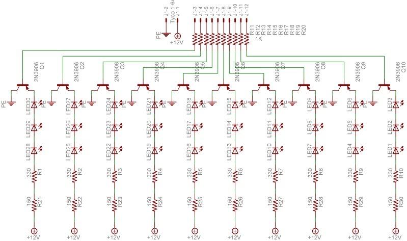
So the schematic is fuzzy, I'm not going to change it. I don't need to. I have the schematic in my CAD program and that's good enough for me.
-
The first schematic didn't use green LEDs, all I had were yellow and red to test my prototype. The actual output of the LM3916s drives 3906 transistors to run blue and yellow/red LEDs.
[img width=680 height=235]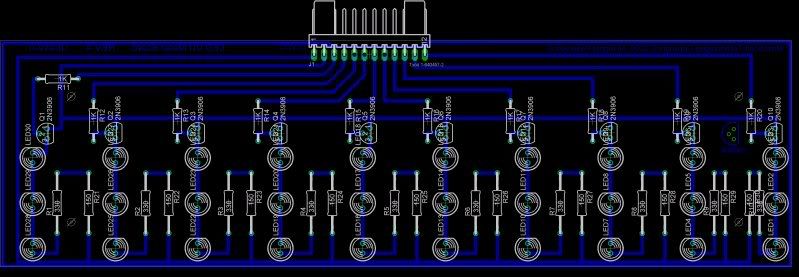
[img width=680 height=510]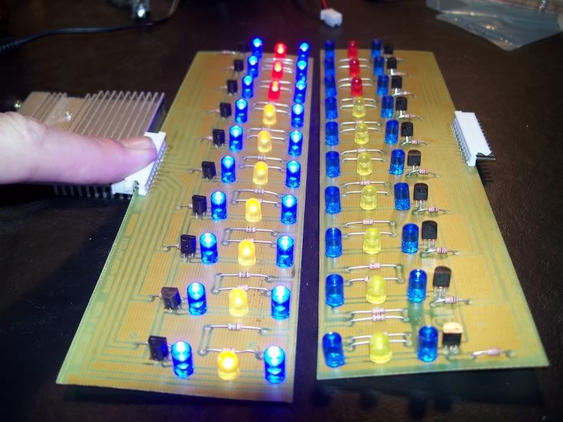
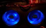
All home made.
I've had my photos at photobucket for over two years with no problems and only change because I changed them. I wanted a rapid response so I opted out of a peak detetctor. This actually increases LED efficiency and longevity as well.
The "fuzzy" is from selecting a low resolution when I converted from my CAD program to JPG.
The rest of the pics - http://s81.photobucket.com/albums/j230/sparky3489/New%20Box%20-%20VU%20meter/ -
Not too shabby for a "too simple of a circuit". Notice the blur, I sure don't.
Oh, and the chips don't get hot either. Where do get all that from?
________________________________
The whole story.
http://s81.photobucket.com/albums/j230/sparky3489/VU%20Meter/
http://s81.photobucket.com/albums/j230/sparky3489/LED%20Panels/
http://s81.photobucket.com/albums/j230/sparky3489/New%20Box%20-%20VU%20meter/

Candle flicker led schematics?
in Electronic Projects Design/Ideas
Posted
You could also just buy some of those LED tea-light candles. Some do have the flicker circuit built into the LED itself.