

Giuflex
-
Posts
14 -
Joined
-
Last visited
Never
Content Type
Profiles
Forums
Events
Everything posted by Giuflex
-

Need data sheet for JFET BFW10,BFW11
Giuflex replied to Sukhbinder's topic in Datasheet/Parts requests
and here it is the datasheet for bfw 11 datasheet_bfw11.pdf -
Need data sheet for JFET BFW10,BFW11
Giuflex replied to Sukhbinder's topic in Datasheet/Parts requests
here it is the bfw 10 datasheet datasheet_bfw10.pdf -
U are wrong from the begining. it doesn't matter which kind of semiconductor U are using, the principle is the same: an electron passes from the covalent band in the conduction band if U give him enough energy to do that. At a normal temperature(18-20 Celsius) electrons inside silicon dopated with n or p type impuritues (and other semiconductor materials used in electronic active components) have enogh energy to jump from the covalent band to the conduction band. The defference between n & p types of silicon is the nature of the impurities unsed to create them. As I remember n type impurities give conduction electrons in the material. I suggest that U go to a library and borrow a book about semiconductors and electronic components made from semiconductors and read it carefully. It's hard to make a summary of such book. Enjoy your lecture!
-
is lc 945p the entire code? i've searched on h**p://www.alldatasheets.com and found something else. U should take a look
-
If you need any other datasheets U can visit h**p://www.alldatasheet.com :)
-
I already have allmost all the components (I have 2 buy IC6).I'm loocking for a 'smart' schematic to control the volume 4 a long time. This one is the most complicated i've found. I have a some experience in the domain (i have this hobby since I was 6, now i'm 19 but I'm still a lamma :) -that's what happens when U don't have strong documentation & some adequated tools) If those links U posted contain schematics I'll build them 2. Thanks! If U have any other links un can post them (I don't mind ;D ). I'm also looking for a HI-FI preamplifier schematic (with 800-1000mVolts on output),this is harder 2 find
-
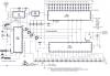
Here is the link 2 it http://www.electronics-lab.com/projects/audio/010/index.html PS: The attachment also contains the image with the schematic
-
Hello, I need some help with the Digital Volume Control schematic (the one with 6 ICs). A small part where S1 & S2 are connecting is missing (left part of the image) Can anybody tell me how (and where) 2 connect those switches? Any attached images, links or other explanations are wellcome
-
U can search a schematic for a car amplifier with tda 1562q. this circuit should give U 70watts RMS (thet's what the manufacturer says) This link should help U a little http://www-us.semiconductors.philips.com/acrobat/datasheets/TDA1562Q_ST_SD_2.pdf
