xsumirx
-
Posts
24 -
Joined
-
Last visited
Never
xsumirx's Achievements
")
Newbie (1/14)
0
Reputation
-
If I have done any Mistake with my Power Supply.. Then can you Please Figure it out !!!! ??? ??? and I have also attested the Schematics of the Digital voltmeter ??? ??? ???
-
Hello, Actually I am designing a Digital Voltmeter using ICL7107. Having capability to measure 0-200v with 0.1 resolution. My Problem is, when I connect the output of 7805 and 7905 to ICL7107 at Pin 1 and 26 respectively. the output voltage become zero at the out pin of 7905 as well as 7805. and not even a single 7-seg Display showing any output Please help me !!!! :'( I am not able to Judge weather its the Problem with my PSU or ICL7107. I have attached my PSU ...... ??? ???
-
I know how to use Google I searched too much ...but still didn't find any circuit which matches with my specification. and I have Posted my Specification: I need output in both negative as well positive mode I need 5v positive as well as 5V negative (i.e; -5V) and +10V and -10V. If you can help me then plz post a schematic.
-
Hello Friends, Actually After Making my PSU, Today I thought to make a SMPS. But the Problem is this I have not the schematics of the SMPS. Can anyone here Give me the schematic for designing my SMPS. My Requirement is below Input Range Vac(in) :- 100v to 250v Output Vdc (out) :- +5V, -5V, +10V, -10V With Feedback Control Plz post your schematics here !!! I need it ;D ;D ;D ;D
-
Function Generator Simulation (Need Help)
xsumirx replied to xsumirx's topic in Spice Simulation - PCB design
Thanks Buddy.....For your Great suggestion, So, I will really work on your advice about power wiring + primary as well as secondary fuse + make the PCB more Neat and this time I gonna design it with a big chassis as it now.... Thanks buddy...again for your Great advice...... :D :D :D :D :) ;) -
Function Generator Simulation (Need Help)
xsumirx replied to xsumirx's topic in Spice Simulation - PCB design
;D ;D ;D ;D Don't Think Like a little baby ....Hero I have tested it upto 4 hour of continuous in ON condition with a 500ohm of Load resistance. Its was working fine for me I am just using 1 amp of transformaer....but I can Handle upto 20A of current and 1 amp is nothing as compare to 20A. Thats why Its will never catches fire at 1A Its Just Looking like mess but I have made some fan funcation also to keep the heat sink cool. I didn't go for ebay shop because I have to submit this project in my college as my Peoject...... I had to made this project with my hand...thats why I did not go for ebay shop. anyway Thanks for suggestion..... !!!! :D :D :D :D :D -
Sorry Brother, I have never used PSPICE, so I can't help you about pspice..... But I will recommend you to use TINA electronics Lab....because Its having more funcation and well user Interfaced enviroments for simulation. I am also using it ..Even I have also tested LM317 based power supply to it and simulation is also well. Even You can add more Library file (.lib) to it. so, I f you will go for TINA(Toolkit interactive Network analysis), I will be definetly able to help you as more as possible. Thankyou !!! :(
-
Function Generator Simulation (Need Help)
xsumirx replied to xsumirx's topic in Spice Simulation - PCB design
I know it Looks dirty and even it can let anyone in confusion......... I can Understand...Ok anyway ....Its all just because it was my first time when I made a PSU indivisiually.... :-\ -
Function Generator Simulation (Need Help)
xsumirx replied to xsumirx's topic in Spice Simulation - PCB design
thankyou audio guru....I have made a power supply using LM723.....I am a beginner right now...thats why I made this simple power supply and working fine for me... Some pics of my power supply Is here : [img width=680 height=510] [img width=680 height=510] and finally Circuit Diagram : [img width=680 height=466] Hows Its -
Function Generator Simulation (Need Help)
xsumirx replied to xsumirx's topic in Spice Simulation - PCB design
okkk...Thanx Tell me one more thing !!! Will BD136 will work instead of BD140. In power supply section -
Function Generator Simulation (Need Help)
xsumirx replied to xsumirx's topic in Spice Simulation - PCB design
your answer take me to 2 different confusion... 1st if the load resistance is 20ohm , then how 40v will flow through the load, so the maximum limit of Vout is just 30v. 2nd if the circuit will do like this then how we will get our desired Vout at the o/p end, in this manner only one thing can be controlled by us voltage or current ? Plz... -
Function Generator Simulation (Need Help)
xsumirx replied to xsumirx's topic in Spice Simulation - PCB design
One thing I still did not understand..... That Current is depend on load resistance. by changing the Load Resistance only the current can be controlled. Can you tell me, How we are controlling the current here ? How we get the desired current output independently to load resistance here in the circuit ? I am completely unknown from this fact. Plz.. ??? -
Function Generator Simulation (Need Help)
xsumirx replied to xsumirx's topic in Spice Simulation - PCB design
Thankyou Audioguru :) ;D This is that answer which I was want to listen in short :D -
Function Generator Simulation (Need Help)
xsumirx replied to xsumirx's topic in Spice Simulation - PCB design
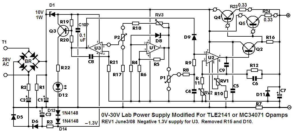
:) Thanks for the tip. I have Finally Decided to make this PS. plz tell me will it work fine as per my expectation My requirement is 0-30v o/p with 0-3A Plz tell me ??? PS_Parts_List_10-11-091.pdf
-
Function Generator Simulation (Need Help)
xsumirx replied to xsumirx's topic in Spice Simulation - PCB design
So, Can u Give me any modified latest schematic for power supply My Requirement is Variable Voltage Output = 0- 30 V Variable Current output = 0-2/3A Actually, I had decided to make the Circuit shown in below post :- http://www.electronics-lab.com/projects/power/001/index.html But, When I went to market (Lajpat Rai market, New Delhi) to purchase Component, Then I didn't found MC34072 Dual opamp. and I stoped the project, So, Can you Give me the any other schematic whose component are available in market or any Other IC equivalent to MC34071