

denci
-
Posts
86 -
Joined
-
Last visited
Content Type
Profiles
Forums
Events
Posts posted by denci
-
-
Hello,
ia have one question regarding heatsink temperature, so i have two IRFP460 mosfet on pretty big heatsink en testing on 4A current and i measured temperature on heatsink after one hour arround 80 degrees, so high. I made calculation and says:
P_Dmax=5A*(12V-(5A*0.1Ω)-5V)=5A*6.5V=32.5W
So max power dissipation is one transistor is 32.5W, thermal resistance THj-c is 0.45C/W. why then so high temperature, i select pretty bigger heatsink that it sould be regarding my calculations??
-
Maybe because missing capacitor on ADC pin to hold voltage??
-
If i burdened battery or. increase discharge current reading of voltage becomes smaller.
I have 33kE and 11kE resistors serial from battery + pin to ground, so this is resistor divider, so if no current flows from battery there is normal reading, when current is higher reading is wrong or smaller as i said, for example battery voltage is 11.5V, adc reading is only 9.5V.
-
I finally figured out where has problem been all the time, ground noise because battery connector.
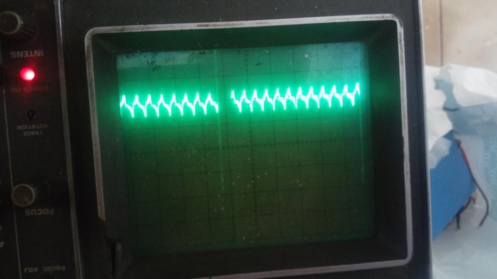
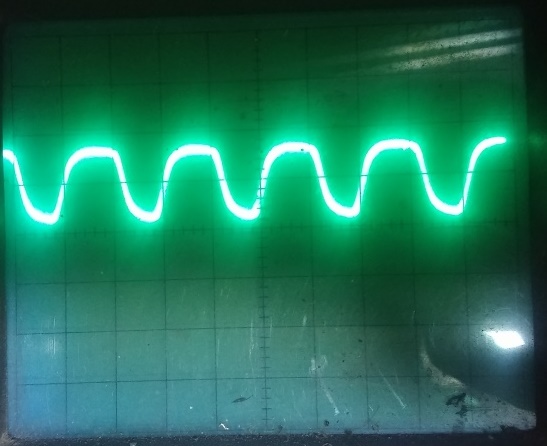
PWM signal is on picture below and you can see oscilating on ground.
I solved this by putting 0.47uF capacitor between battery connector and signal is smooth and now voltage on -pin is the same as on +pin (which is suprising me, so voltage inequality reflected by input noise of OP????) but i must perform test also with higher current but for now this is part of solution.
-
Thanks but i gave an example of measurements in previous posts, mosfets are IRFP460, so only problem is that voltage on - pin does not follows voltage on + pin, regarding mosfet transistor Vds should not be a problem for this case.
I wondering why voltage on - pin is lower than voltage on + pin and ouput voltage of OP is lower as i exepected - in upper case only 5.5V.
-
I measured 5.5v on op output when input voltage is 1v, then voltage on r4 resistor is 0.75v, current is 1.6a, power supply voltage was set on arround 11.8v.
So if increasing voltage of power supply (which represent battery) than current is increas to arround 1a and than stops increasing which is logically, so mosfet most probably not suitable for such a battery voltage.
-
I am using mosfets IRFP460, regarding datasheet these transistor are suitable for project, i will check LM324 output voltage and then report values.
However problem is that battery voltage is reduce by high current so theoretically when 10A is flows out of battery, 5V is on R4, battery voltage could reach critical value arround only 9V (depends of battery healthy) and then source voltage of mosfet is only 4V, so mosfet can provide high current only on that condition, or not??
-
So i have changed filter and improve ground and provlem with currenr spikes is now solved.
I was testing circuit with power supply instead of battery and i figured out that current decreasing with bat voltage decreasing which is not allowed, maybe because too small mosfet drain to source voltage, i must find 22e resistor and put it into circuit also but most probably this is not because of gate resistor missing??
Voltage on - pin is little bot lowe again that voltage of +pin of op i must solve this too.
-
Ok i sould adding resistor.
So, do you still think that the signal spikes represented on picture above is reflected by poor ground, i must perform test once again i add some kind of "star" ground so all gnd is connected at one point with thicker wire.
-
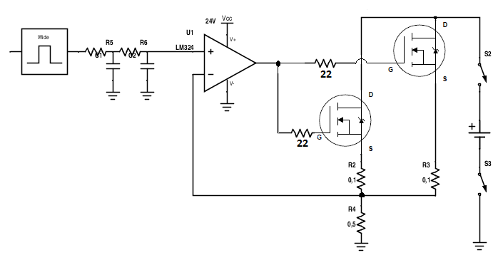
This is schematic you suggested me, only different is that there is no 22E resistors to mosfet gates.
-
,
Your ground wire is too thin so it acts like a resistor that has a votage drop across it. You need a "star" ground that has all grounds together at one point then there is no ground wire for a voltage to develop across.
So i forgot to tell you that i have separate PCB board, one is power board and one is control board and only thin wires (flat cable) connecting them together so this is the main problem i must provide low resistance ground.
I have other question, why voltage on -op pin is not equal (aprox. 20% lower) then on +input pin (voltage follower orientation)??
-
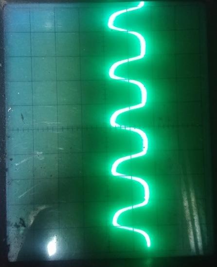
I placed thicker wire in some ground places in order to avoid voltage drop as you said above and also put the thicker + and - connection wire for battery connection and problem solved when discharged current to above 2A is flowing, but when increasing current using PWM modulation as described above (increasing duty cycle) signal starts oscillating (picture from scope - some kind of charging capacitor).
So do i have improve ground further to decrease voltage drop??
All works fine but only because of oscillating i have wrong adc reading and i need to use adc averaging but also using this result not precise as i wanted to be!
-
is this parasite capacitance?
otherwise i solved problem with thicker positive and negative wire for battery connection but wires must be close together, if they aren't effect of capacitance appear again!
-
With spacing between battery wire (+ and - cable), signal is increasing it's shape like above, when wiring of battery so close together ther is just some little spikes appear on signal how can i avoid this problem, how can i get dc signal on discharging resistor while battery being discharged.
-
TNX for your help audioguru I try with better ground and there is no such a signal as above any more!!
This was solution, I have very thin ground connection between battery ground and mcu ground so I add thicker wire.
-
Thicker ground wire?? Where exactly??
Circuit is very simple to understand but i have bad dreams about this unstable working


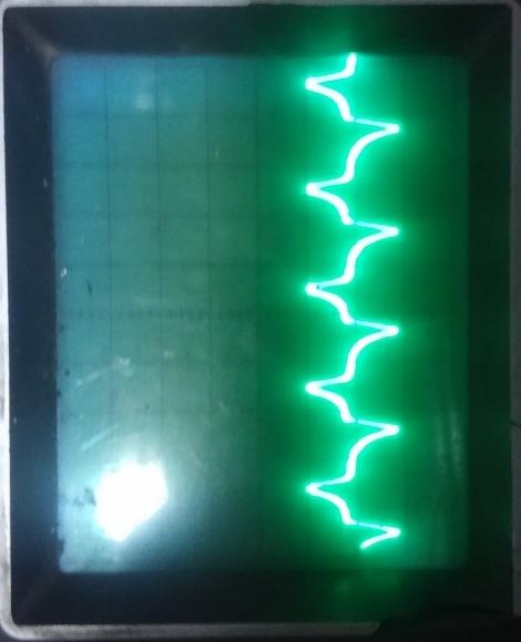
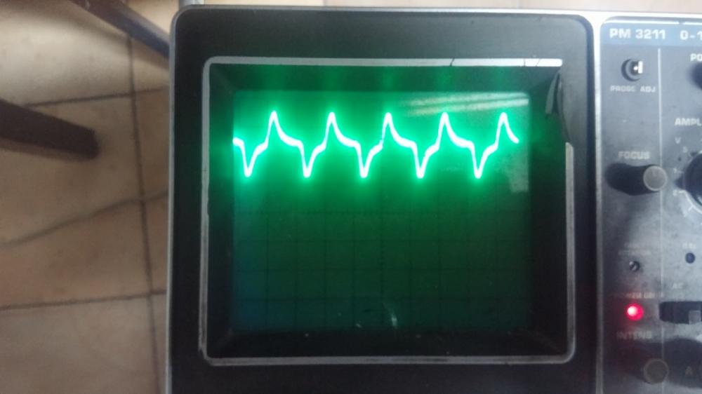
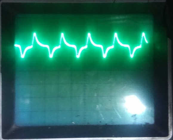
So i made some onother measurements with scope and i figured out that when i put bigger resistor in rc filter, for example 1ME (1ME and 100nF) thern i have small smaller dc signal but stable under discharge process. Problem is to sensing current via shund to atmega adc, resaults is unstable, picture belows shows signal on mosfet gates:
Voltage is unstable from OP output (scope settings is 1V p-p), so that is because unstable current flow from battery.
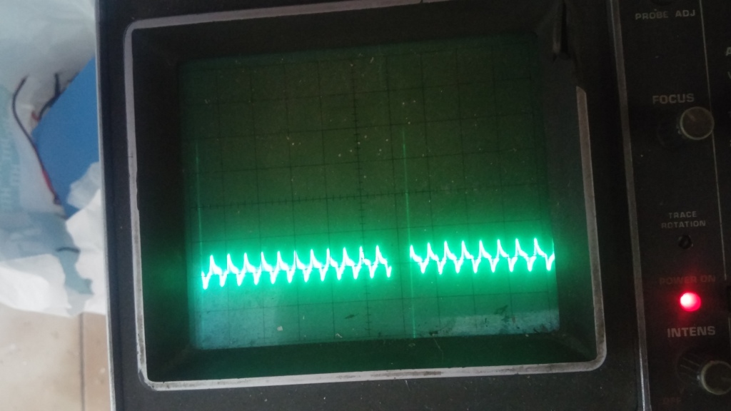
Onother interesting thing happening on circuit, when i put scope ground on battery ground there is signal like in picture from post before (charging and discharging capacitor), when i put scope gnd to gnd of OP, there is dc signal on current RC low pass filter also with smaller resistor - 100kE+100nF like before!!
the same thing happenig when put scope to Vcc pin of atmega MCU, signal is like in picture below, off course when i start discharge battery:
-
Yes, but why this happening when I try to discharge battery through 0.5E resistor, current is controlled with software regulated PWM output, is this signal appear because OP oscillate via feedback??
I just wondering how to always provide DC signal to load resistor to ensure that always flow also dc current through system.
-
Your RC networks are lousy filters:
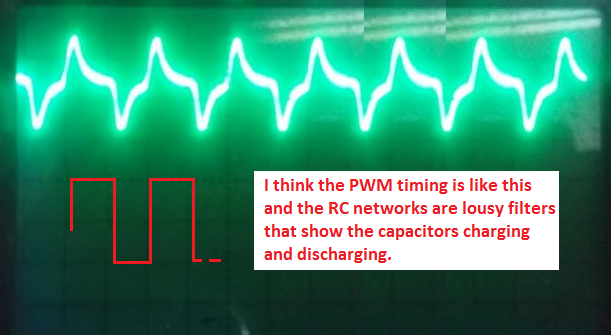
compare pictures between each other and you can see that there is positive and negative noise because of the same centre value of signal.
Why this negative noise??
-
i testing also direct on pwm pin od MCU and when battery is charging there is a lot of noise in ground, in upper case is 10% duty cycle so i don't know if that kind of signal is reflected by RC loos, or??
Maybe OP is critical here in this circuit??
-
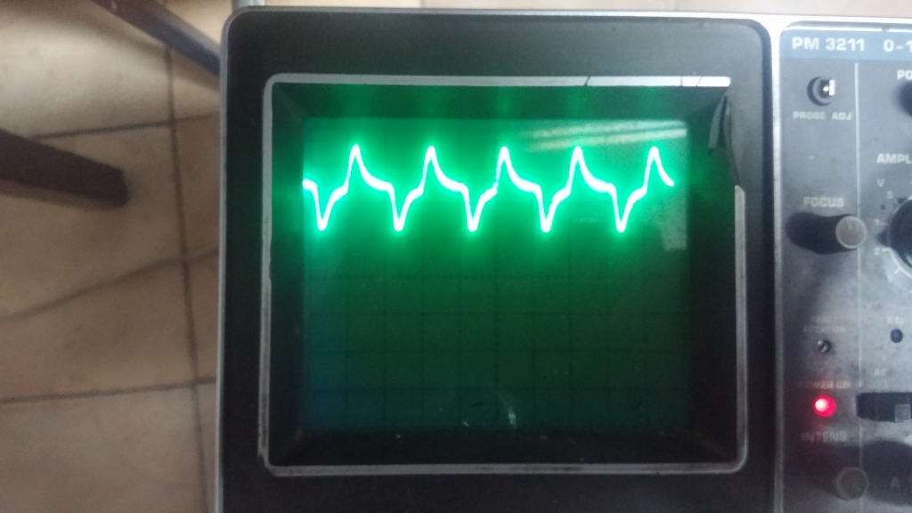
Hello again, i have had problem with RC filter from PWM but i solve it with proper resistor and capacitor value and i get DC signal into positive pin of OP, see picture below.
When i put 100 bit value i get around 0,5V which is OK.
There is one onother problem which i have still not solve till now, when i connect battery and start to discharge it the signal from RC is like below:
Do you know why this happening??
-
It's maybe batter to add 100E restor from 24V supply to BD139 collector and onother 100E resistor between emmiter and output transistor bases?
Or there should be additional relay to provide open circuit while battery is disconnected and no current flow when battery isnt present at all?
-
Have you any other idea to prevent this or are you think that OP is defected?
-
No, the opamp and transistors are a follower. 0V input gives 0V output at the 0.5 ohm resistor. +1V input gives +1V output at the 0.5 ohm resistor. +10V input gives +10V output at the 0.5 ohm resistor producing a current of 20A.
220 ohms between the emitter of the BD139 and the bases of the output transistors limits the current in the BD139 and reduces the base current in the output transistors.
If the battery is not connected then if the input of the opamp has a positive voltage then the BD139 will more current than when the battery is connected.
I cannot remember why you want to kill a battery by discharging it.
This is exactly the main problem in circuit, if battery not connected and positive voltage apply in + iput of OP by chance, so this mean that high current try to flow through BD139 and 220E resistor and buri it.
Circuit is for battery test purpose, programmable cotrol discharger to test battery healthy and compare quality between each battery pack.
So i have a big problems because PCB is already made and no big chance are allowable there any more, so i try to find solution to current flow in ouput transistor base.
Maybe other solution is available there because as i said there is relays too and when relays is not activated i wan to no current flow except we select program to start discharge the battery.
TNX for your helps!
-
If there is a positive input voltage to the opamp (+) input, the current flows from the emitter of the BD139 through the base-emitter diodes of the output transistors and through the low value resistors to ground. The 1k emitter to ground resistor of the BD139 also has current in it. When there is 0V on the discharge power resistor then there will be no current in it and no current in any other part.
When i have 0V on + input pin of opamp LM324 then i have 24V on ouput and bd139 is turn on end also when i put resistor 220W between BD139 emmiter and ouput transistor bases. This is all againts how i want to circuit works, maybe something wrong with opamp?
Is there any chance to no current flow at all throught circuit even battery is no conected and regardless what in input voltage on + input pin of OP, because anyway there is additional relays which turn on battery and it starts discharging?


Current monitor/sensor
in Electronic Projects Design/Ideas
Posted
Yes, but what with 5V voltage drop on 0.5E dischatge resistor? Is this nedd to take into account, or? Now i tasted with 4A, so 2A only through each mosfet and i measured 75degree per C on heatsink so from calculation is junstion temperature is allowed range.
Is that not truth?