micromacro
-
Posts
12 -
Joined
-
Last visited
micromacro's Achievements
")


-
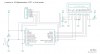
Hello, please help me to distinguish is this common cathode or common anode connection 4 digits, 7 segment display? Schematics in attachment.. Thanks ;)
-
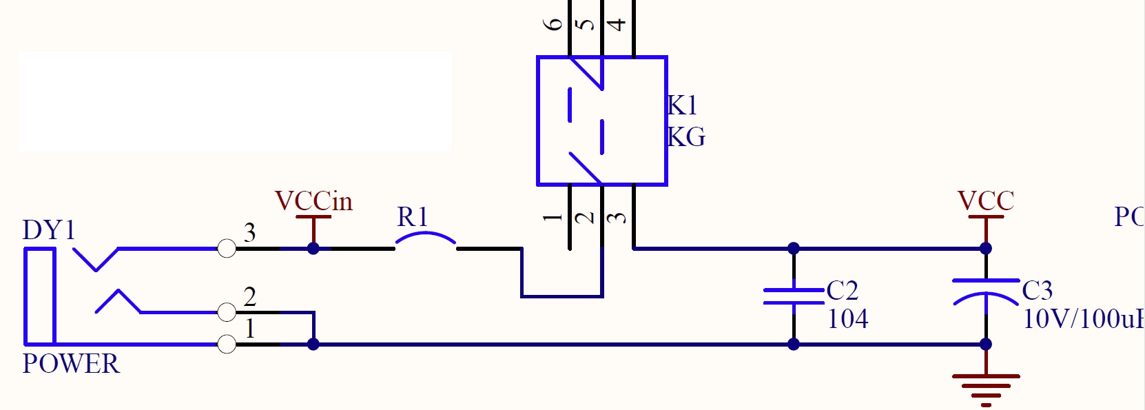
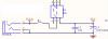
Or should I ask what is R1 on my schematic? Resettable fuse? schematic in attachment.. Thanks
-
I see power supply connector & USB are in that circuit..
-
I am soldering parts on my PIC16F877A learning board. But I have insufficient info about R1 component on upper left corner.. Can you help me figure out what kind of resistor is that? Schematic and PCB on photos: http://imageshack.us/photo/my-images/823/45106697.jpg/ http://imageshack.us/photo/my-images/825/46087841.jpg/ http://imageshack.us/photo/my-images/189/79845887.jpg/ Thanks ;)
-
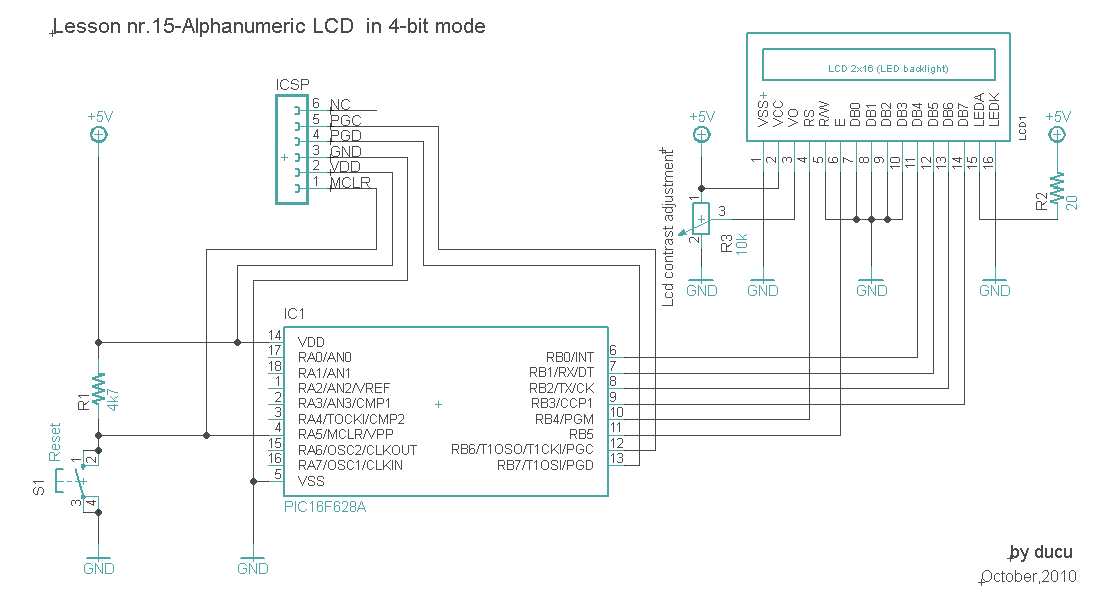
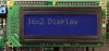
ooops my mistake.. my LCD is 2x20 characters.. maybe code needs to be modified? maybe this LCD has different initialization routine than 2x16 LCD code is written for? Thanks
-
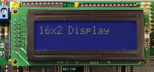
Hello, I connected everything like on shematics. I made hex file after succesfull build in mikroC and burned it on pic16f628a... but all I get is black boxes in first row of my lcd. Can you tell me where am i going wrong. I have LCD with side connections like one in attachment.. */ // LCD module connections sbit LCD_RS at RB4_bit; sbit LCD_EN at RB5_bit; sbit LCD_D4 at RB0_bit; sbit LCD_D5 at RB1_bit; sbit LCD_D6 at RB2_bit; sbit LCD_D7 at RB3_bit; sbit LCD_RS_Direction at TRISB4_bit; sbit LCD_EN_Direction at TRISB5_bit; sbit LCD_D4_Direction at TRISB0_bit; sbit LCD_D5_Direction at TRISB1_bit; sbit LCD_D6_Direction at TRISB2_bit; sbit LCD_D7_Direction at TRISB3_bit; // End LCD module connections // Define Messages char text1[] = "Testing LCD"; char text2[] = "using PIC16F628A"; char text3[] = "Test successful"; char text4[] = "in 4-bit mode"; void main() { Lcd_Init(); // Initialize LCD do { Lcd_Cmd(_LCD_CLEAR); // Clear display Lcd_Cmd(_LCD_CURSOR_OFF); // Cursor off Lcd_Out(1,3,text1); // Write message1 in 1st row Lcd_Out(2,1,text2); // Write message1 in 2nd row Delay_ms(3000); // delay 3s Lcd_Cmd(_LCD_CLEAR); // Clear display Delay_ms(1000); // delay 1s Lcd_Out(1,2,text3); // Write message3 in 1st row Lcd_Out(2,3,text4); Delay_ms(3000); // delay 3s } while(1); }
-
Let's say I would like to make PSU like this one: http://www.electronics-lab.com/projects/power/001/index.html but with lower voltage considering my transformer. Thanks!
-
Hello, I would like to build laboratory power supply, but I am not having much sucess in finding suitable transformer for one that is described in Electronics Lab projects. Is this transformer suitable for such a use (lab power supply)? 60VA European type (input: 230V AC 50Hz): Standard: EN61558, EN60065, EN60555 Case size: 101 x 63 x 74mm Weight: 1090g Model number: DE-60-12W: O/P: 12V AC, 5.00A, 60A It looks like one in attached picture.. Thanks a lot ;)