-
Posts
23 -
Joined
-
Last visited
Recent Profile Visitors
3,380 profile views
liquibyte's Achievements
Newbie (1/14)
1
Reputation
-
There's an executable in there. Why?
- 10 replies
-
So, you come to a board that posts schematics regularly for projects and post a project without any real information and then request peoples email addresses to send them information? Does anyone here think this is a good idea to get information on the project given that a quick ebay search shows entire projects with code and all as downloadable material. My spidey sense tells me something's amiss here.
- 10 replies
-

0-30 VDC Stabilized Power Supply 0.002-3 A
liquibyte replied to CBETO3AP's topic in Power Electronics
I'm sorry, I should have said I think it's the wrong value for this configuration. I'd have to work out the math for it but I think you'd do better with a much lower value at 10A output. Doing that would require also adjusting the resistor values around the voltage reference and current regulation circuit. -

0-30 VDC Stabilized Power Supply 0.002-3 A
liquibyte replied to CBETO3AP's topic in Power Electronics
R7 is also the wrong value for this configuration. -

0-18V Pos/Neg 1A Current Limited
liquibyte replied to liquibyte's topic in Electronic Projects Design/Ideas
I tried my best to fix a few of the more glaring issues that I had while I was testing. The one thing that always bothered me was the current sense heater. I felt like I should be using this as an on demand water heater. I'm actively working on prototyping out the changes to see what works and what doesn't. The one thing we lose is getting voltages close to 0V but I don't think anyone really needs that either. I haven't looked at different op amp solutions yet because the TLE214x family worked so well but my guess is that a nice rail-to-rail could go in there now without issues due to the 36V regulator circuit and come close to addressing that issue. My focus was on the transient issues and a better current sensing scheme. I'm planning a voltmeter/ammeter for this using modern parts. 12bit ADC, Atmel microcontroller (up for debate but I've got some blank 328P-PU's), and a MAX7219 to drive the displays, and a 4-wire sense resistor. Doing the meter is more for the educational value than anything else for me but some folks might find it useful so I plan on releasing everything all at once when testing is complete. -

0-18V Pos/Neg 1A Current Limited
liquibyte replied to liquibyte's topic in Electronic Projects Design/Ideas
You can do a search for output decoupling caps to ground and you will find several references to 1uF to 2.2uF for the values in an effort to solve oscillation. I used these because of that actual problem I was having. I do understand each component in the circuit having studied it extensively and having modelled it in LTSpiceIV extensively to arrive at the circuit that I posted. Bringing in linear regulators to the circuit added nothing to the conversation whatsoever. I did not copy that other circuit, I based mine off of that configuration. By the way, the 0-30V circuit uses the same principles and quite a bit of the same configuration. I don't know if you've noticed but I posted a modified version of that circuit that I'm working on as well. I removed the part of the circuit that was the negative regulator because it really added nothing to the circuit and introduced issues that has made it hard to fix. We now have a 10V reference and a 0.1 ohm current sense resistor that suffers from much less heat than before. Still think I don't understand what's going on? -

0-18V Pos/Neg 1A Current Limited
liquibyte replied to liquibyte's topic in Electronic Projects Design/Ideas
-

0-18V Pos/Neg 1A Current Limited
liquibyte replied to liquibyte's topic in Electronic Projects Design/Ideas
The fact that you even suggested that circuit tells me that you either know nothing and are trying to fake it or that what you think you know is entirely wrong. Linear regulators as a lab supply is just stupid and I'm tired of seeing that dumbass circuit all over the net being suggested as so. -

0-18V Pos/Neg 1A Current Limited
liquibyte replied to liquibyte's topic in Electronic Projects Design/Ideas
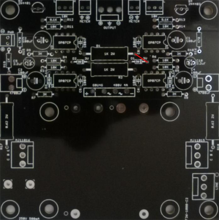
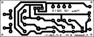
Your change adds significant oscillations to my simulation output on the positive side of things. As for the 2.2u cap, it could have just as well been 1uF but 2.2uF is what I had on hand that solved the issue I was working on also in regards to oscillations. I got the value from doing some research into problems I was having and this was a recommended solution and, no offence, it worked. I'd link what I was reading but I can't find it again. Suffice to say that it was from a reputable source and not instructables or the like. I think it was actually an ap note and I'll link it if I find it. The bottom line is that while math and theory can go a long way, up until you build something you never know what you're going to get. Oh, and always run board checks. The missing trace was a dumb mistake on my part. The pic of the board shows the fix I had to do. This is a redesign of something I found online and wanted to see if I could simulate it an manipulate it to do what I wanted. My changes worked so well that I wanted to put it on a manufactured board so I did. -

0-18V Pos/Neg 1A Current Limited
liquibyte replied to liquibyte's topic in Electronic Projects Design/Ideas
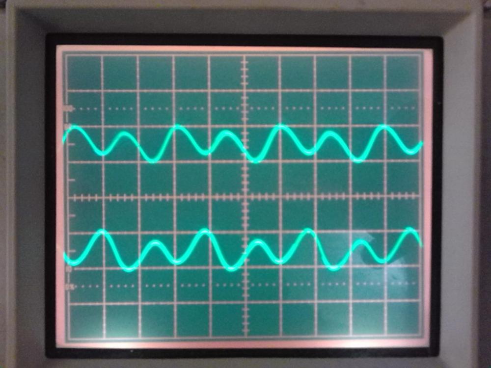
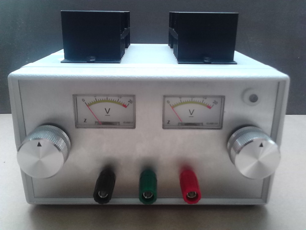
You guys are late to the conversation. I've had the boards made and from my testing things work rather nicely. I did make a mistake on the gerbers and forgot to connect D2 to R2 but since it was a short hop, I left the lead on the zener long, folded it over and soldered it to the lead of the resistor on the bottom. I have no way to vary the current dynamically and I'd not imagine anyone doing that so I'd say, all in all, things work as expected with no oscillation at all. I've got less than 20mV ripple at full load on the output. For what I designed this for, I'd say it works nicely. -
Yeah, I know. I did the math from the datasheet and given what the simulation is giving me, I'd say the device can probably handle it. I don't have the equipment to lay this out and test in the real world but PD from both amps only total around 300mW and if I'm reading things right, the 2142 can probably handle it. It turns out that I was under a wrong assumption about the power handling capabilities of op amps in general.
-
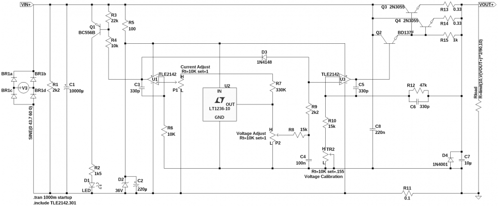
Many, many questions keep getting asked about this thing and people keep attempting to build it without even knowing the basics, why I don't know. The power supply suffers from a couple of issues that have never really been adequately addressed so this is going to be my attempt at bringing this thing into the modern age. What follows is just preliminary work to right several wrongs I've noticed with the design. It's not complete but I'm posting it to get opinions and suggestions. This paragraph is for the newbies: DO NOT ATTEMPT TO BUILD THIS YET. If you don't know what you're doing, do not even try and breadboard this. Once I have a final design, I promise that I'll post it. Now, onward. I'm posting my spice simulation for anyone that wants to try and give this a go. One of the things that concerns me is the power dissipation in the op amps but I'm not sure how to get this down to a more acceptable level because I don't think 150mW at load is very good so suggestions are most welcome. First, the voltage reference in the old version was an extremely odd thing to me so what I wanted to do was get a precision reference in there to work with. 10V seemed like a nice round number so that's what I went with and I actually have one on hand to use. Second, the sense resistor. 0.47 ohms? Once again, odd. Plus, it suffers from extreme power dissipation as well. My idea is to have a nice 0.1 ohm 3W 4 wire resistor in there to hook a meter to so I adjusted things around the reference to get me to where I wanted to be and I also have some of these. What I'd like to eventually do is design the meters along with the supply so that what we end up with is a relatively complete project with all the nice bits people seem to be after. No one, I repeat, no one ever offers a suggestion as to what to build to replace this, not one single engineer. They will, however, be the first people to tell you how bad the design is but never offer any sort of advice as to why. I know, I've asked and so have many other people. 0-30V-0-3A-redesign.zip
-
Seriously? https://www.google.com/search?q=control+pic+through+internet&ie=utf-8&oe=utf-8
-
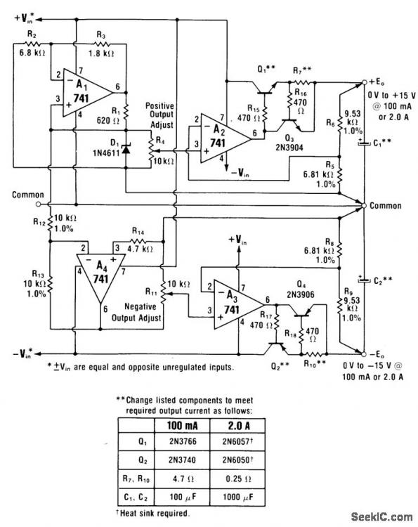
I guess one of the learning experiences when one gets into this hobby should be blowing things up so that you learn how not to. I just posted these from the archive that the user posted because just about everything was a pdf file save the schematic. I have no idea what format the design files were in or what program they open with so ymmv. I get why you'd want to use a linear regulator for a quick and dirty supply but I don't understand their ubiquitous use with newbies. You don't really learn anything designing with them in my opinion. Trying to design one with discrete components on the other hand...
-


