Sherldonnnn
-
Posts
4 -
Joined
-
Last visited
Content Type
Profiles
Forums
Events
Everything posted by Sherldonnnn
-
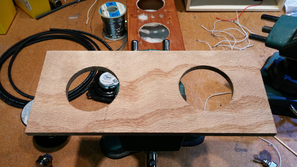
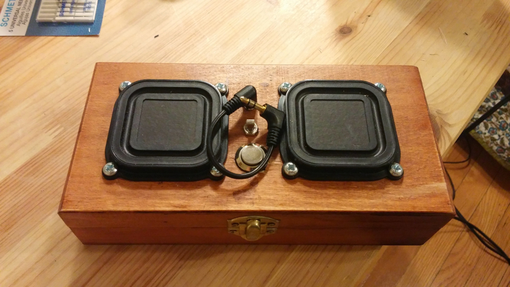
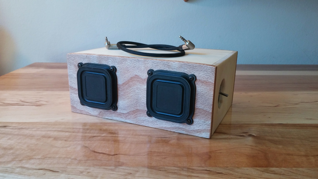
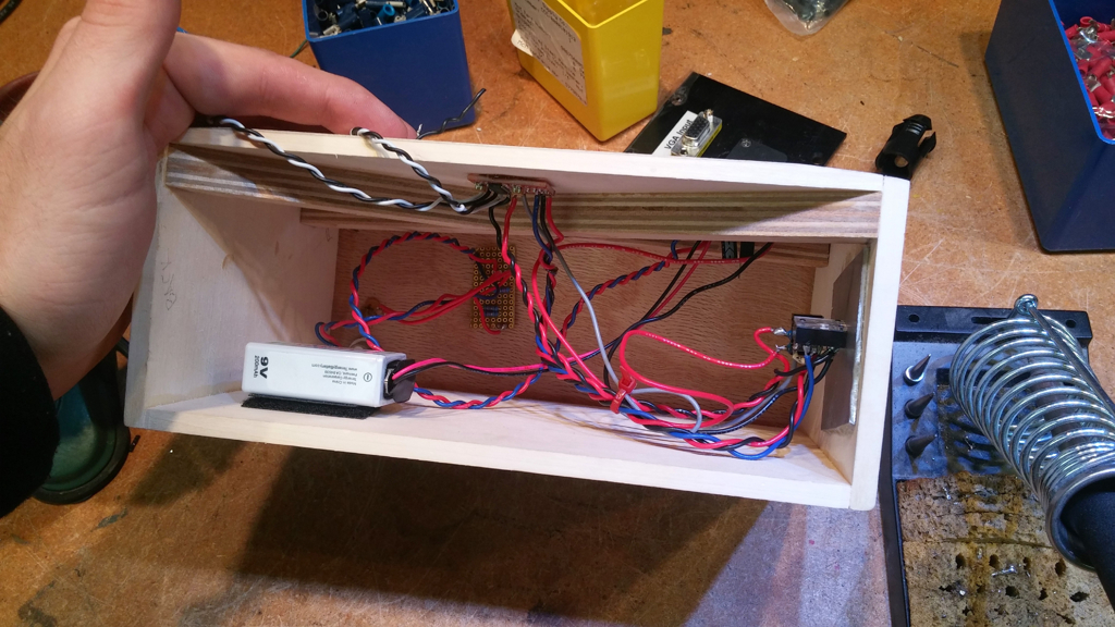
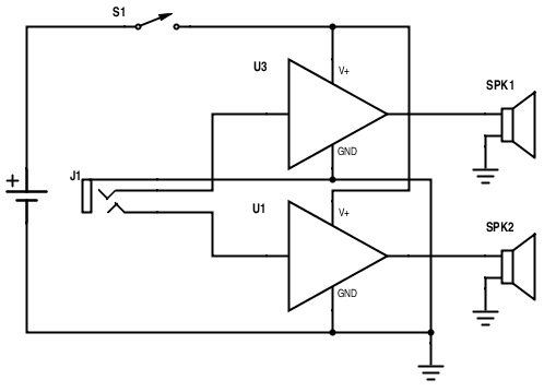
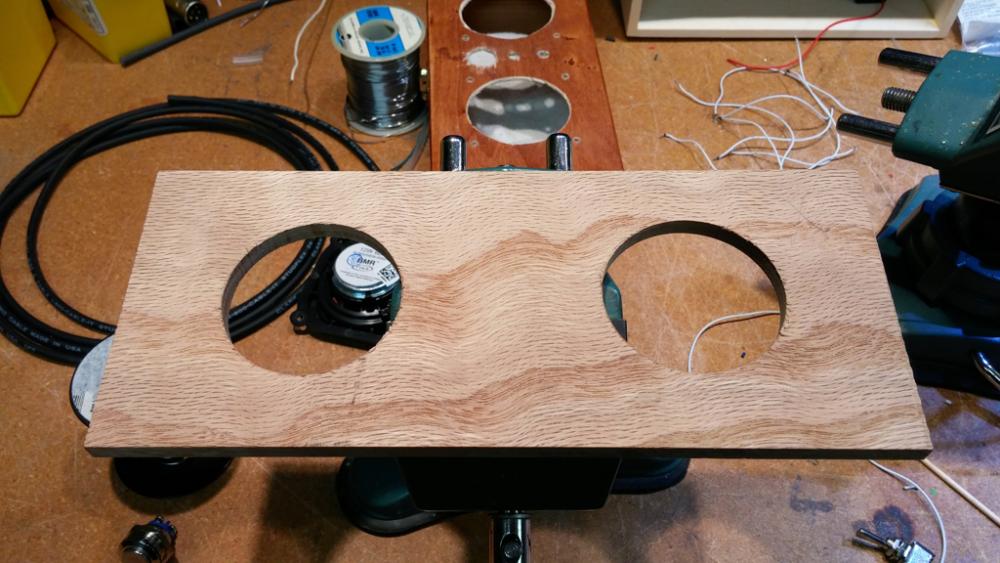
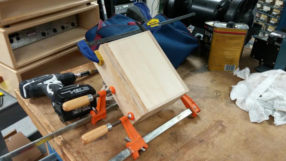
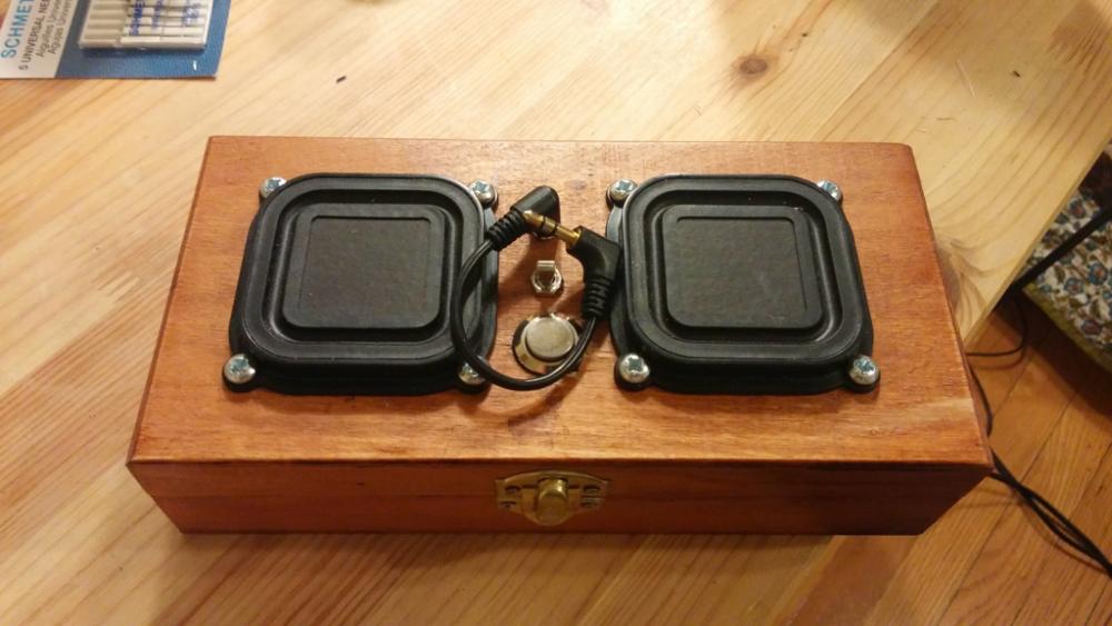
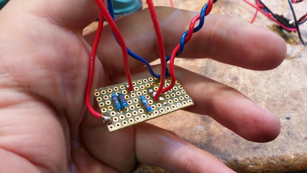
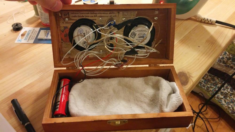
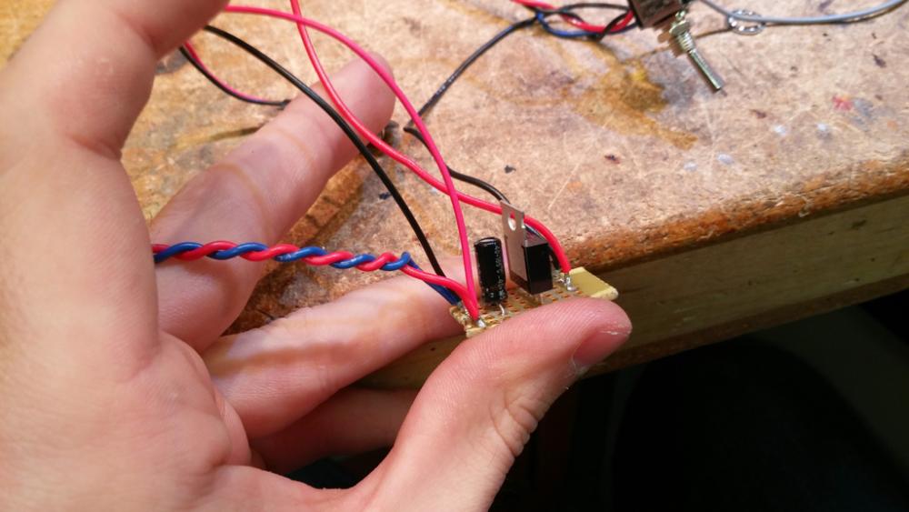
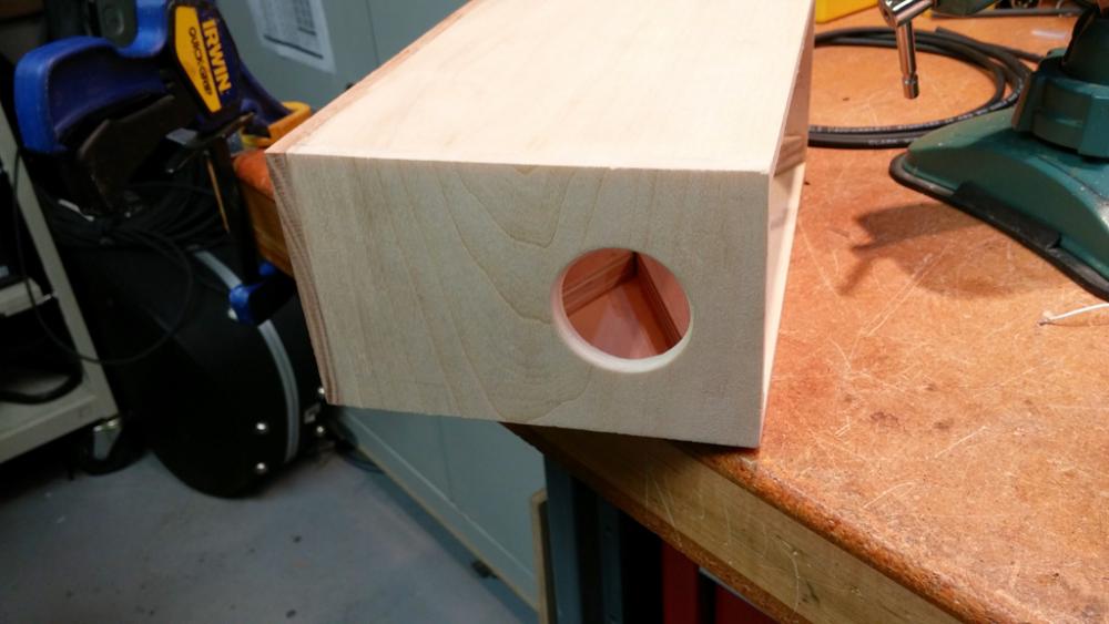
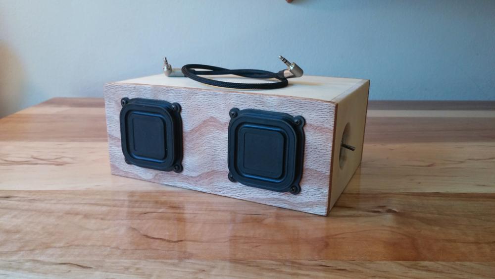
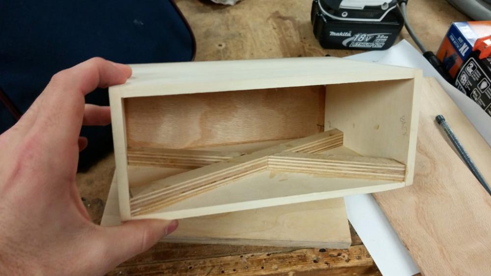
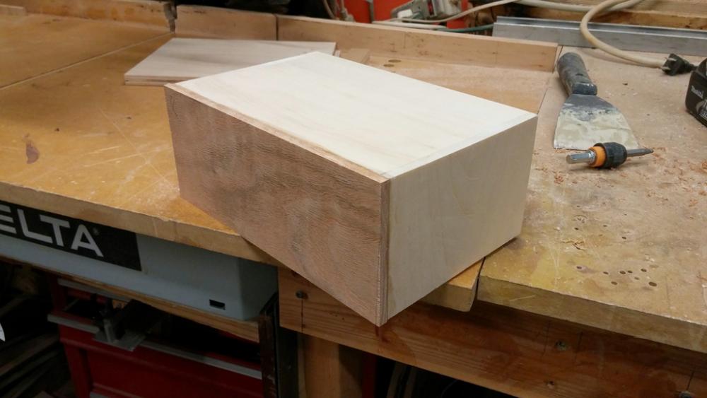
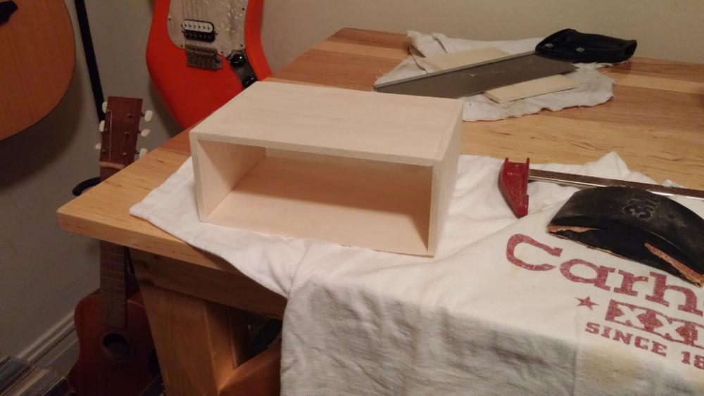
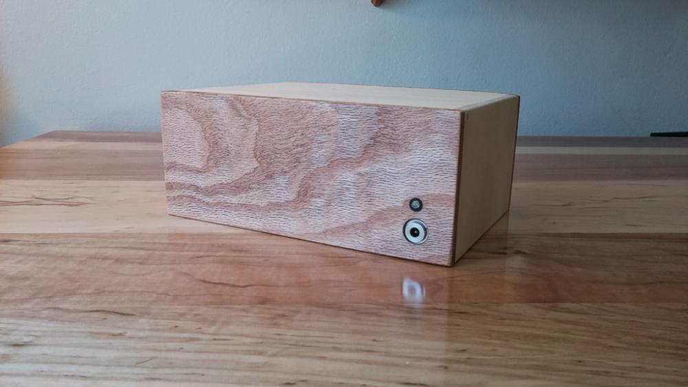
This is a sharing of a portable speaker design project. Have you ever thought about designing and building your own portable speaker? A project like this is both easy and cheap if you source your parts wisely and have basic knowledge of electronics, soldering, and box construction. The first question you have to ask is, "What do you want this to do?" If you want 40 Hz bass extension, then you will have to design for it. If you want high SPL, again, you will have to select an amplifier and loudspeaker combination that can provide that. What did I want? I wanted a portable, battery-powered stereo speaker of moderately high fidelity. Bass extension was not a concern, but "punch" was. From this, a sealed enclosure was selected. Before building the version you see above, I prototyped the circuit on a breadboard with an enclosure made from a wooden quill box that I cut two holes in with a box cutter. The basic circuit diagram for this prototype was nothing more than connecting the audio to the amplifier and the amplifier to the speakers (well, provide the power too). For reference, the diagram is shown below. (THIS IS NOT THE FINAL DESIGN, SCROLL DOWN FOR THE FINAL ITERATION) The amplifier here is a 3W stereo IC-based audio amplifier that I ordered from a Chinese website(http://www.kynix.com/Detail/647721/PAM8403.html). It cost me $2. For $2, I figured I would give it a try. Pretty simple, right? Just connect it together the logical way. Now that I've shown how it went together, maybe I should share the parts list of the V1 electronics. There will be more components added in a minute. Parts List V1 Stereo 3W Audio Amplifier (PAM8403) x1 3.7V 1860 Li-Ion Battery & Battery Holder x1 1/8" Stereo Jack (or whatever you would like to use for the input) x1 SPST (single pull, single throw) Switch x1 Loudspeaker x2 (preferably 4 Ohm, I used 8 Ohm) I prototyped this circuit on a breadboard just to convince myself that what I had designed would actually work, and was surprised at the quality of the amplifier. There was distortion at higher volumes, but this was a result of the amplifier wanting 5V and the battery only capable of supplying 3.7V. I highly recommend this amplifier for all low power applications. Being as excited as I was, I quickly shoved the electronics in the quill box. I added a mute switch along the way, which was just a momentary switch connected to ground and a pin on the amplifier. It looked like this. Opening the box and exposing my hurried soldering and poor wire management... Some of the connections are twisted and taped together since I planned on transplanting it into a proper enclosure. Notice the clean sock. So, I built the skeleton of the enclosure that same night out of aspen, a soft wood that you would not normally build an enclosure out of, but it was what I had on hand and is very forgiving when I make mistakes. You can use whatever material you like to construct the box, but a common choice is MDF. MDF is made from sawdust and glue, with the mixture being compressed into the boards you buy at the store. The product is perfect for this purpose since the material is not of uniform density and does not sympathetically vibrate at frequencies we are concerned about. I chose the aspen, which you have already seen, for the sides and red oak for the front and back faces. I have tools available on this site for enclosure design, and they work great for calculating necessary box volume on a project like this. My box was build from the output of the tool and then the dimensions increased ever so slightly to lower the system resonance at the expense of system Q. I lost some of the "punch" in the bass I mentioned I was after, but I gained a deeper reach. Then I glued the rear face on the box. Designing as I went, I decided to add an "X" brace to the top of the enclosure to help minimize the low frequency energy lost to the panel. It was made from strips of 1/2" plywood and glued to the inside. Using a forstner bit, I cut two holes for the speakers on the front panel and one on the side for the audio jack and power switch. It would have been easier to cut the hole for the steel panel prior to gluing the box together, but you live and learn. Electronics V2 To mitigate the distortion at high volumes, the 3.7V 18650 was swapped for a rechargeable 9V. Since the amplifier only accepts voltages up to 5.5V, a 5V regulator was necessary. A filtering capacitor was also added to the circuit even though there is minimal noise from a battery power source. This was when the issue of charging the 9V became a problem. I had originally purchased a micro-USB charging module that would have charged the 18650, but the module's fully charged voltage was 4.7V. The regulator needs altleast 5V to let current pass. So, I had to design a charger myself. Googling a circuit to charge a 9V yielded a number of possibilities, but for simplicity I chose to go with a single 20 Ohm resistor to limit the current into the battery. There is no protection for the battery this way, but I included an LED that will turn off when the battery is fully charged. This charger also charges very slowly (approximately 14 hours for a full charge), which minimizes the risk of me leaving it on the charger too long. You will need any 9V wall-wart to supply power. The regulator and charging circuit are shown below. I then drilled two holes in an 1/8" steel plate and mounted the switch and audio jack to it. After wiring it all together, it just needed to be test one final time and mounted in the box. Parts List V2 Stereo 3W Audio Amplifier (PAM8403) x1 9V Rechargeable Battery 1/8" Stereo Jack (or whatever you would like to use for the input) x1 SPST (single pull, single throw) Switch x1 5V Regulator 10 uFarad Capacitor 20 Ohm resistor for 9V Charger Barrel Jack for charger Loudspeaker x2 (preferably 4 Ohm, I used 8 Ohm) Final Assembly Now it is done! Do you want to have a try? Then go on with it! If you have any question, please leave a comment below~Thanks for reading.


-
I was testing some things on my protoboard to learn a little about transistors. I made this: The batteries are two AA 1.5V in series. The resistor is a 1Kohm. The transistor in a TIP122(http://www.kynix.com/uploadfiles/pdf9675/TIP122.pdf) npn darlington. I uploaded a code that just put Pin9 as OUTPUT and HIGH, so I can test the currents on the circuit. 1.Current beetwen the Pin9 and the Resistor: 1,32mA. 2.Current beetwen the Baterry(+) and the Colector: 0,43A. 3.Current beetwen the Emissor and the Ground: 0,32A. I can`t understand this currents. I was expecting 3mA ((5-2)/1000) on the 1st case and 3A (1000(gain)*3mA) on the 2nd and 3rd. Am I doing something wrong? Is this circuit going to damage my Arduino, since there is 0,32A going to the Ground Pin?
-
Hi everyone !!!I'm starting to learn c lenguage for PIC and i would like to realize one dot matrix 8x8 display with an microcontroller someone can help me ? Which is the right step to introduce this particular range argument because i want focus my study for any particular argument so I can obtain more results with less difficulties.I don't know lenguage C for microcontroller in depth but i know any other similar lenguage like Java, Visual Basic and so ,now i'm studing one book that have this title "Pillole di MICROCONTROLLORI PIC " of Editor Company "INWARE" , you know ? Is 64 LED 8x8 module. My intention is to pilot module 8x8 led in a special PCB board realizzed myself or if is there in a market i can buy one for my experiment. I've seen ,in internet, one project that use any particular TTL integrated like "74HC164 SHIFT REGISTER" but is 5x24 because use one PIC16F628 from http://www.kynix.com/Detail/1205929/PIC16F628A-I%2FML.html and three TTL driver. I think is interesting project but it has any problem if use any particular display because there are some TTL that are not suitable and so depend which component you use for realize acceptable result. Those module that you have described me are realized for experiment and i think is necessary usb port in a PC to can make any experiment while i want to realize one project with independent one power supply and all component inside a box. I want to realize one display like counter and pilot it with transceiver module and in a bottom of this counter i want to display one message of my choice. This module is very cheap and so i can use two lines module. I'm very interested to this argument and i've learned any possibile application and know register ,I/O pin and how i can set fosc ,pullup and so , i think is not particular difficult because are not treated expecial concept like inherits encapsulation polymorphism that are three pillars of concept OO lenguage. This book is associated with any application like Micro PRO editor that have library manager that import and invoke class only ability any flag in this pannel.I've seen only any particular void method and set any register because there are already construct library and for this reason is necessary know only how work this class and method and parameter associated. I think is very interesting electronics industry and interesting applications but most difficult concept is how handle this informations. I would be very grateful if you can help me to focus any particular argument that are interested for this particular sector. Arey you really sure that PICKIT3 is enough for this application ? If you have also treaty this arguments for this particular sector i can buy one for my experiments because is very restrained cost. This solution i think is possible but if i want to pilots suppose one display with two line ten module each one i must take a lot resistor and also transistor to pilots them. I think is more difficult realize master and probably dimension of board increases, imagine two line of this display how many resistor i insert in my board and how many transistor ? If i decide to use for example this layout module this is display specifications:Display Dot Size: 3.0mmMaterial: GaAsP/GaPEmitted Color: OrangePeak Wavelength: 635 nmForward Voltage: 2.1 - 2.5VAbsolute Maximum RatingsReverse Voltage(Vr): 5 VForward Current (If): 30 mAPeak Forward Current (Ifp): 150 mAPower Dissipation (Pd): 80 mwOperating Temperature (Topr): -40oC to +80oCwhat do you think about ? How i can drive it with an PIC microcontroller ?
-
Hi, I hope this is the right sub-forum. One of the SMD devices that I thought was just a PNP transistor for supplying 5v to LEDs turns out to be a BCR185W - PDF datasheet - which is a digital transistor. New to me. I wonder if anyone can explain things below to me in a way that my awkward brain can understand please? I did wonder why the faulty microcontroller on the control board had no resistor between its output pin and the base of the BCR185W and from what I can glean after reading a webpage all about understanding digital transistor datasheets (it helped a bit, but still don't understand a lot of it) that is because there are resistors built into the transistor. Am I right that this has been done so that logic level outputs (0v and 5v) can be directly connected to the transistor, with the inbuilt resistor being tailored so that when the 5V is applied, the base current is just right to turn the transistor on in saturation mode so it really does act like an on/off switch? I'm struggling to understand the functioning of transistors in general which doesn't help despite reading umpteen webpages on them. Any help much appreciated: Assuming NPN, I understand that a transistor has a voltage requirement to the base to cause current flow C to E. I now realise after much reading that the current is important as the current at the base alters the current C to E flowing through the transistor. I don't know what part of the datasheets for transistors tell me what base current I need to apply to get the transistor into saturation so that it passes the full allowable current C to E. Going back to the base voltage. I gather that most transistors need about 0.6v to 0.9v to the base. I've found most transistors in circuit I've tested with a voltage meter show more than that to the base. I've done lots of reading to educate myself and wonder if I've got this next bit right (I'll write it as if it's fact because I am writing what I think is the case, but want to be corrected please!): A transistor only uses whatever base voltage it requires, so let's say in this instance 0.7v. If 5V is put on the base then still only 0.7v is travelling from base to emitter, being used as it were. It needs a certain amount of current to saturate, below that it is in linear mode and the amount of current it allows to flow C to E (gain) is proportional to base current. So, if you have a 5V supply and you choose 1mA current to the base, then you need to disperse 4.3v at 1mA, so you use a 4.3K base resistor. If you want 2mA at the base, you use a 2.2K base resistor. Because of the relationship between voltage and current, would you measure voltage (assuming emitter to ground NPN) from ground to base and read 0.7v, or would you read a different voltage that depends on what current you are supplying to the base, even though only 0.7v is flowing from base to emitter? If we measured either resistor used above, you would still read 0.7v at the base, then why do I find higher voltages on bases on so many transistors I check in working circuits? I'm really confused. Will the base draw whatever current it can pull, and the resistor will cause the voltage to drop as more current is drawn, so you'll always read 0.7v on the base? If anyone has the time, could someone please look at the BCR185W datasheet I've linked to and tell me, using a PIC, what base resistor I'd use to turn it on in saturation mode, and most importantly, how you arrived at that, what parts of the datasheet you looked at, how it was calculated, etc? (even if the built-in base resistor means there's no calculating to do, it can just be connected straight to the PIC I/O pin.) It'll help me understand the calculations and how to read the necessary parts of the datasheet. Thanks. Sherldonnnn