

Linksprite-Yuki
-
Posts
34 -
Joined
-
Last visited
Content Type
Profiles
Forums
Events
Posts posted by Linksprite-Yuki
-
-
It is capable of real-time detecting the presence of smoke, detection of visible particles (smoldering fire) faster than ionization smoke alarms. Red LED flashes rapidly and detectors sound alarm once detecting smoke fire danger, can alert you and your family timely.


Features[edit]
- Operating voltage: DC3V(CR123A Lithium Battery)
- Static current: ≤10μA
- Alarm current: ≤60mA
- Networking way: ZigBee Ad-Hoc Network
- Sound level: 85dB/3m
- Distance of Ad-Hoc Network: ≤100m (open area)
- Working Temperature: -10℃~+50℃
- Working humidity: ≤95%RH
- Dimension: 60*60*49.2mm
Tips[edit]
- 1.This detector is designed specifically for home
use, may not able to provide sufficient fire alert for public areas.
- 2.Please avoid installation in bathrooms and
other very humid places, dusty or greasy areas, or very airy place with air conditioning, ceiling fans, etc.
- 3.Please keep detectors clean, and do not let
dust accumulated. It is recommended to clean every 6 months with a household cleaner and a soft brush.
- 4 . T h e e ff e c t i v e l i f e s p a n i s 1 0 y e a r s .
Replacement every 10 years, regardless of breakdown or not (battery life: 3 years). 5.Please pay attention if it alarms. Besides proper use of alarm, we should also strengthen the consciousness of fire safety.
-
It is capable of real-time detecting the presence of smoke, detection of visible particles (smoldering fire) faster than ionization smoke alarms. Red LED flashes rapidly and detectors sound alarm once detecting smoke fire danger, can alert you and your family timely.
Features[edit]
- Operating voltage: DC3V(CR123A Lithium Battery)
- Static current: ≤10μA
- Alarm current: ≤60mA
- Networking way: ZigBee Ad-Hoc Network
- Sound level: 85dB/3m
- Distance of Ad-Hoc Network: ≤100m (open area)
- Working Temperature: -10℃~+50℃
- Working humidity: ≤95%RH
- Dimension: 60*60*49.2mm
Tips[edit]
- 1.This detector is designed specifically for home
use, may not able to provide sufficient fire alert for public areas.
- 2.Please avoid installation in bathrooms and
other very humid places, dusty or greasy areas, or very airy place with air conditioning, ceiling fans, etc.
- 3.Please keep detectors clean, and do not let
dust accumulated. It is recommended to clean every 6 months with a household cleaner and a soft brush.
- 4 . T h e e ff e c t i v e l i f e s p a n i s 1 0 y e a r s .
Replacement every 10 years, regardless of breakdown or not (battery life: 3 years). 5.Please pay attention if it alarms. Besides proper use of alarm, we should also strengthen the consciousness of fire safety.
-
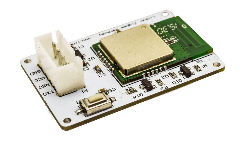
Linker ZigBee gateway module is one kind of Linker modules which can communicate with up to 32 ZigBee node devices. It is powered by Marvell 88MZ100 ZigBee microcontroller SoC chip. This ZigBee offers advantages for many application scenarios, including lighting control, smart metering, home/building automation, remote controls and health care applications.
-
Marvell MZ100 ZigBee SoC chip
- A ZigBee compliant platform and IEEE802.15.4-2003/2006 transceiver
- 32 bit ARM Cortex M3 microcontroller running at 32 or 64 MHz with Marvell’s proven peripheral IPs
- On-chip DC-DC converter that can directly take input range from 2 volt to 3.6 volt
- UART serial communication protocol
- Linker port with 4 pins
- 3.3V
http://linksprite.com/wiki/index.php5?title=File:118101035-new-1.jpg
-
Marvell MZ100 ZigBee SoC chip
-
LinkNode R8 is a WiFi relay controller and it is powered by ESP-12f ESP8266 WiFi module which is comptiable with Arduino programming. There are 8 relay channels and each channel allows you to control high-power devices (up to 10 A) via the on-board relay. LinkNode R8 can be used to remotely turn lights, fans and other devices on/off. The WiFi interface will allow you to associate the board with your existing WiFi network and send the commands over the network.


Features[edit]
- ESP-12f ESP8266 WiFi module
-
8 Channel relays,supporting:
- 277V AC, 10A
- 125V AC, 12A
- 7-28V DC power
-
Two work modes:
- Program via UART
- Boot from flash
- 8 indiator LEDs
-
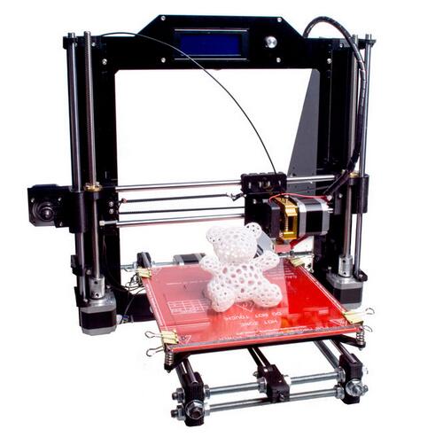
Prusa i3 (i3 stands for third iteration of the design) is the latest design by LinkSprite. There are countless variations of the design and it became a staple of 3D printing with tens, if not hundreds, of thousands units world wide. You can build simple one for couple hundred dollars or you can chip in more and get the state of the art 3D printer, it’s all up to you.
It’s open functional design allows for quick maintenance. For example if our LinkSprite DIY 3D printer Prusa i3 Kit breaks you can clean it in couple seconds! This makes i3 great workhorse 3D printer for your business. Not to mention the ability to upgrade the printer as you wish without manufacturer forcing you to buy a new model! Future-proof FTW!
Technical Specs
- bigger build volume – 8000 cm3 (20x 20x 20 cm or 9,84 x 8,3 x 8 in)
- Open frame design for easy use
- Integrated LCD and SD card controller
- 0,5mm nozzle (easily changeable) for 1,75 mm filament
- Layer height from 0,1 mm
- Supported materials – PLA, ABS, PET, HIPS, Flex PP, Ninjaflex, Laywood, Laybrick, Nylon, Bamboofill, Bronzefill, ASA, T-Glase, Carbon-fibers enhanced filaments, Polycarbonates...
- Easy multicolor printing based on layer height
- Average power consumption 70 W (printing PLA) or 110 W (printing ABS), exterior dimensions 43 x 42 x 40 cm (16.9 x 16.5 x 15.7 inches), weight 7.27 kg (16.03 lbs)
- Specially optimized firmware for quiet printing
-
This product is Smart Motion Sensor, adopts extra low power consumption ZigBee wireless network and automatic threshold adjustment technology to enhance the stability of the detector, efficiently anti-false alarm. Automatic temperature compensation technology, can efficiently prevent detectors from the decrease in sensitivity resulted from the temperature variation. Suitable to be used for safety protection of residential, villas, factories, shopping malls, warehouses, office buildings, banks, computer room and other places.
-
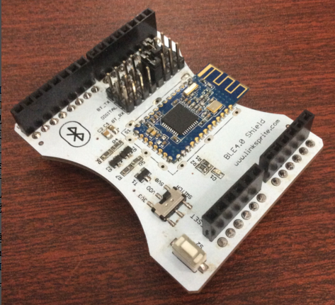
The Bluetooth 4.0 BLE Pro Shield for Arduino (Master/Slave and iBeacon) integrates an openhapp Serial Bluetooth BLE module HM-10. It can be easily used with Arduino for transparent wireless serial communication. You can choose two pins from Arduino D0 to D7 as Software Serial Ports to communicate with Bluetooth Shield (D0 and D1 is Hardware Serial Port).
Support Central and Peripheral mode switch, modify by AT command.
Support Remote control mode, remote device can control PIO pin or modify settings by AT commander when Connected. (such as Iphone4s/5 ipad, Note2 etc.)
The Bluetooth UART serial Converter Module can easily transfer the UART data through the wireless Bluetooth, without complex PCB layout or deep knowledge in the Bluetooth software stack, you can combine this bluetooth module with your system:
- MCU, ARM or DSP systems.
- SOC systems.
- Personal Digital Assistants (PDAs)
- Computer Accessories
- Other systems your want to use under bluetooth functions.


Features[edit]
- CC2541 Bluetooth Chip Solution
- Fully Qualified Bluetooth V4.0 Ble
- Full Speed Bluetooth Operation with Full Piconet Support and Scatternet Support
- Increadible samll size with 3.3V input, and RoHS Compliant
- UART interface and with baudrate setup function
- iBeacon
- Size: 28*13*2.3mm
Schematics[edit]
Usage[edit]
AT Command:
- AT (Test command)
- AT+BAUD (Query/Set Baud rate)
- AT+CHK (Query/Set parity)
- AT+STOP (Query/Set stop bit)
- AT+UART (Query/Set uart rate,parity, stop bit)
- AT+PIO (Query/Set PIO pins status Long command)
- AT+PIO (Query/Set a PIO pin sttus Short command)
- AT+NAME (Query/Set device friendly name)
- AT+PIN (Query/Set device password code)
- AT+DEFAULT (Reset device settings)
- AT+RESTART (Restart device)
- AT+ROLE (Query/Set device mode, Master or Slave)
- AT+CLEAR (Clear remote device address if has)
- AT+CONLAST (Try to connect last connect succeed device)
- AT+VERSION (Show software version information)
- AT+HELP (Show help information)
- AT+RADD (Query remote device address)
- AT+LADD (Query self address)
- AT+IMME (Query/Set Whether the device boot immediately)
- AT+WORK (if device not working, start work, use with AT+IMME command)
- AT+TCON (Query/Set Try to connect remote times)
- AT+TYPE (Query/Set device work type, transceiver mode or remote mode)
- AT+START (Switch remote control mode to transceiver mode)
- AT+BUFF (Query/Set How to use buffer data, Duing mode switching time)
- AT+FILT (Query/Set device filter when device searching) A
- AT+COD (Query/Set Class of Device. eg: phone, headset etc.)
-
The pcDuino4 Nano is an Allwinner H3 based ARM board. It is only two thirds the size of the Raspberry Pi. It is open source. It works with Ubuntu MATE, Debian and etc. The pcDuino4 Nano uses the Allwinner H3 Soc. It integrates Ethernet, IR receiver, video/audio output and supports HDMI and AVOUT. It can be powered via the MicroUSB port In such a small board it still integrates rich interfaces and ports. Besides the popular HDMI, Ethernet, USB-Host, USB-OTG, DVP camera interface and AVOUT (audio and video) it has an onboard Microphone, IR receiver, a serial debug port and a Raspberry Pi compatible 40 pin GPIO pin header.

Specification[edit]
- SoC – Allwinner H3 quad core Cortex A7 @ 1.2 GHz with an ARM Mali-400MP2 GPU up to 600 MHz
- System Memory – 1GB DDR3 SDRAM
- Storage – micro SD card slot
- Video & Audio Output – HDMI and 3.5mm jack for CVBS (composite + stereo audio)
- Connectivity -10/100M Ethernet
- USB – 3x USB 2.0 host ports, 1x micro USB OTG port
- Camera – DVP Interface
- Expansions – 40-pin Raspberry Pi compatible header with UART, SPI, I2C, PWM, GPIOs, etc…
- Debugging – 4-pin header for serial console
- Misc – Power and reset buttons; 2x LEDs; IR receiver; on-board microphone.
- Power Supply – 5V/2A via micro USB port; 4.7V ~ 5.6V via VDD pin on “Raspberry Pi” header.
- Dimensions – 64 x 50mm (Orange Pi One dimensions: 69mm × 48mm)
-
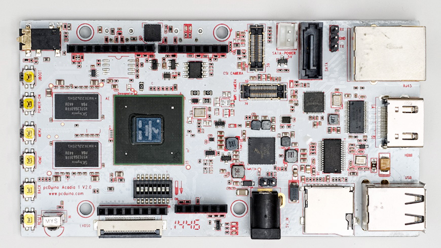
pcDuino Acadia
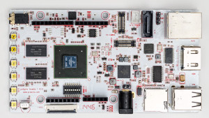
I will start off by actually loading the OS onto the Acadia’s eMMC storage.
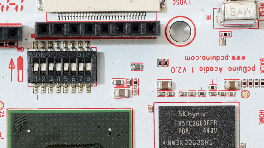
First download the firmware updating software from here and unzip it on to your windows PC. With the Acadia turned off make sure all of the boot configuration switches are set to the OFF position.
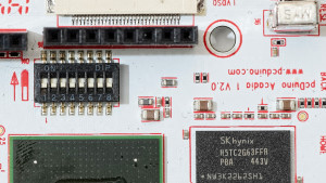
OFF-OFF-OFF-OFF-OFF-OFF-OFF-OFF
In the download folder of the firmware updater you should find a file named “cfg.ini”. Open this file in a text editor. There should be a line that says, “name=Acadia-eMMC”. If not, make the change and save it.
Run the MfgTool2.exe program. Connect the Acadia OTG port to a usb port on the PC and power it up. A few drivers should be automatically installed. The MfgTool2 app should say, “HID-compliant device”, in one of the top text boxes when its ready. Click “start”. This will take some time to complete and it should say, “Done”, when finished. Click stop and exit. We should be done with this program for now.
Power down the Acadia and change the configuration switches to boot from eMMC.
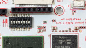
ON-ON-OFF-ON-OFF-ON-ON-OFF
Attach SATA cable and power cable to Acadia. Power it up and it should boot from the eMMC. Open Disk Utility and create a root partition and format it. In my case it was /dev/sda1. I then used dd to copy the root system to the hdd with this command below.
1>ddif=/dev/mmcbkl0p1 of=/dev/sda1 bs=1M conv=noerror,syncThis took some time as well. Once completed, unmount the partition using disk utility. In a terminal window we are now going to convert the ext3 partition to ext4 by using these commands.
123>sudo tune2fs -O extents,uninit_bg /dev/sda1>sudo e2fsck -f /dev/sda1These will take a little while as well. There were errors found on mine and they were corrected.
Next we must modify the u-boot environment variable to have /dev/sda1 mounted as root. To do this we need to connect to the Acadia debug port. For this I used PuTTY and created a serial connection to that port with settings of 115200,N,8,1. From this terminal window I issue the “reboot now” command.
When the Acadia comes back up it will pause for a few seconds and ask you to hit enter to exit the boot routine. I will admit that it took me a couple of tries before I got it.
At the u-boot prompt type the command.
1u-boot>priYou should see a listing of the boot up script. Somewhere in there you should see a line that says something similar to, “bootargs_mmc=……”. We are going to replace that line only changing the “root=” variable. Yours may vary depending on video settings, etc. Duplicate your line and change it to read, “root=/dev/sda1”. So my command would be something like below.
1u-boot>setenv bootarg_mmc'setenv bootargs ${bootargs} root=/dev/sda1 rootwait fec_mac=${ethaddr} video=mxcfb0:dev=hdmi,19200x1080M@60,if=RGB24,bpp=32 fbmem=28M'Notice the single quotes. They are required. Execute the command to save it.
1u-boot>saveenvUse the pri command again and look at the bootargs_mmc variable just to make sure. It will be at the bottom of the list now.
1u-boot>priPower down the Acadia. Then power it back up.
If all went well you should now have root filesystem on the hdd.
-

The MAX6675 performs cold-junction compensation and digitizes the signal from a type-K thermocouple. The data is output in a 12-bit resolution, SPI™-compatible, read-only format.
This post we will demo how to use the MEGA+MAX6675 to measure water temperature.Room temperature and the hot temperature, as the follows:
The


-
This LinkSprite PWM shield adds 27 independent PWM channels to Arduino or pcDuino by using a dedicated PWM generation MCU: STM32F103C8T6. All the PWM pins of STM32 can support up to 5V.
The total number of PWM channels is 27. The duty cycle can be adjusted. The channel number is labeled on the shield as below:


The four jump headers next to pwm 27 are for the selection of communication ports, such as SPI, UART and I2C. Right now, the sample code we provide has only SPI interface.
The external power supply is specified to be between 7V to 24V. The three pins header SWD is for firmware download to STM32.
The PWM shield has 27 PWM channels in total. Among these 27 channels, the 16 channels implemented by hardware in STM32 are 2, 3, 4, 7, 8, 9, 10, 11, 17, 18, 19, 20, 22, 23, 24 ,25, and are divided into four groups. The channels within the same group has same output frequency, but with different adjustable duty cycles. Channels 2, 3, 4, and 7 are in the same group, channels 8, 9, 10, 11 are in the same group, 17, 18, 19, 20 are in the same group, and 22, 23, 24, 25 are in the same group. The other channels are implemented by software, and each channel has its own frequency, but the higher the frequencies, the worse the resolution.
The communication protocol is as following:
/****************************Message format***************************************
index Byte1 Byte2 Byte3 Byte4 Byte5 Byte6
mean START CMD INDEX VALUE_L VALUE_H CHECK_SUM
********************************************************************************/
The command has 6 bytes in total:
The command starts with a first byte “0x87”.
The second byte is the commands that need to be executed. The supported one are following:
#define CMD_SET_ON_OFF 0x01 (Turn on or off)
#define CMD_SET_POLARITY 0x02 (Polarity of the signal)
#define CMD_SET_FREQ 0x03 (Frequency of the signal)
#define CMD_SET_DUTY 0x04 (Duty cycle of the signal)
Description of the parameters:
1. The range of the duty cycle is between 0-10000, which corresponds to 0-100%.
2. The precision of the channels implemented by software is 5uS, and the ones implemented by hardware is 0.5uS.
-
 NFC( Near Field Communication Technology) by RFID( Radio-frequency identification) evolved, and now this technology has been widely used in mobile devices, the mobile with NFC-enabled can act as access cards, transportation cards, credit cards and so on, this to say, it makes the mobile devices more widely.
- 1 x Arduino UNO
- 1 x NFC PN532 Shield
- 1 x NFC label
1. Put the NFC label close to the sensing area and you will see the return news from the serial area.

If read the correct label, the serial will print out Found 1 tags
The back number of read card # is the corresponding ID number.

-
BLE4.0 Shield is an arduino shield which based on TICC2541. The AT instruction set integrated by BLE4.0 module is simple and effective to use, and greatly shorten your developing period. Based on the bluetooth standard specification, Bluetooth Low Energy (BLE) technology allows BLE4.0 to further reduce peak power to half, comparing with traditional Bluetooth devices. The single-mode chip of Blue tooth4.0 (BLE) enables to work for a long time (up to several months even years), powered by single button battery. Instead, traditional Bluetooth technology generally asks for at least two AA batteries, meanwhile at most works for several days or weeks. The main disadvantage of previous blue tooth version is extremely low startup speed. For example, Blue tooth 2.1 spends 4s to startup, but it’s only takes 3 ms for Blue tooth 4.0 to startup. If comparing Blue tooth 2.1 to a basic “feature phone”, then, Blue tooth 4.0 would be a “smart phone”.
Arduino UNO x1
BLE4.0 Shield x1
mobile device with Blue tooth 4.0 x1
-

This product is a smart temperature and humidity detector,adopts extra low power consumption ZIGBEE wireless network technology, using MCU to the temperature and humidity intelligent processing, with functions of dust-proof, insect-sproof, etc. Ensuring the stability of the product from the design. With high precision temperature and humidity sensor built-in, it can perceive and report real-time temperature and humidity to APP. The product is suitable for environmental monitoring in residential, factory building, computer room, shopping mall, hotel, office building, teaching building, bank, library, as well as the warehouse and many other places.
Features
- Operating voltage:DC3V (1 CR2450 button battery)
- Standby current:≤10uA
- Networking way:ZigBee ad hoc network
- Wireless networking distance:≤100m (open area)
- Operating temperature:-15℃~ +60℃;
- Ambient humidity:Maximum 95%RH
- Outline dimension:60x60x20.8mm
Tutorial
we will show how to interface Deepcam ZigBee Temperature and Humidity sensor using the Linker ZigBee gateway, and serves as a basic framework for home automation sensors application.
Prerequisites
- pcDuino3B or pcDuino8 Uno x 1
- ZigBee Gateway module x 1
- Linker Base shield x 1
- Zigbee Temperature and Humidity x 1
Steps
1. Hardware connection
According to the following diagram to connect pcDuino3B, ZigBee gateway and other equipment.

2. Download the ZigBee gateway demo code
Turn on pcDuino3B, open a terminal and download the zigBee gateway code from the github. We also need to modify the
-
Download source files
https://github.com/delongqilinksprite/zigbee_hum_tem.git
Note: You have to install pyserial in the system.
4. Add the Temperature and Humidity sensor
- Run the zigbee.py program get temperature
Press and hold the RST pin hole of the Temperature and Humidity sensor until the green LED blink fast. Now we can start to add device and run the code:

change the code line 226

<code>python zigbee_tmp.py
</code>
- Run the zigbee.py program get temperature
change the code line 227

<code>python zigbee_tmp.py
</code>
5. How to add more ZigBee devices
Follow the steps above, we have been able to add a device, and we continue to add other devices. but we shuld use another code program and more information ishere:
More sensors can be found at here.
-
In cases, we would like to track down the pcDuino in the field. This can be achieved by check the CPU serial number of pcDuino. In this post, we show how to check the CPU serial number information.
We can get CPU ID by loading cpu_id.ko (this is built for pcDuino 2). The following are the commands we typed at the terminal of pcDuino:
1234$ sudo insmod cpu_id.ko$ cat /proc/cpu_idVER:CID:165166c380485370515248480301dc8b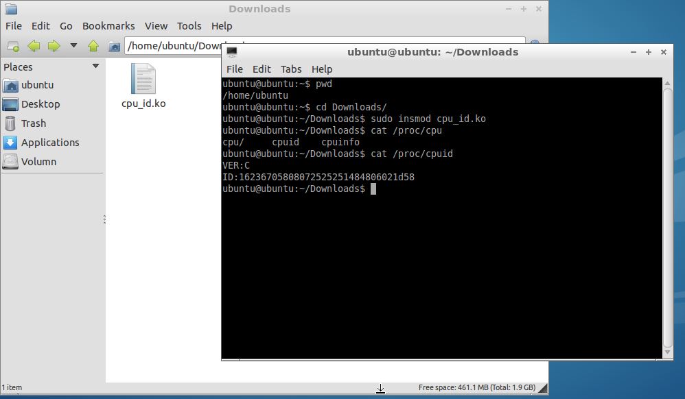
The source code can be found at: https://github.com/pcduino/modules/tree/master/sun4i-cpu-id
The ko file for pcDuino3 can be downloaded here.
To buiild the ko file for pcDuino3, we need to first install the dependency software package:$sudo apt-get install pcduino-linux-headers-3.4.79+
Then we need to change the kernel location in Makefile to 3.4.79+, and comment out:
/*
case MAGIC_VER_A:
ver=’A’;
break;
case MAGIC_VER_B:
ver=’B’;
break;
case MAGIC_VER_C:
ver=’C’;
break;
*/in file cpu_id.c.
-
Linker kit is a set of LEDs, sensors, actuators, displays, etc modules that defined to have a common interface. It makes very convenient to conduct projects without the breadboarding or soldering. In this post, we will look at how to use linker kit modules on beaglebone with the help of a linker base shield that is designed for beaglebone.
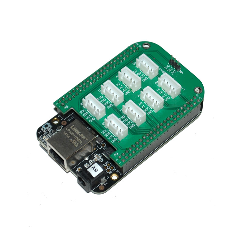
There is a jumper header on the linker base shield for Beaglebone to select the logic level of the interface to be 3.3V or 5V.
1. Software environment
We are going to use the Adafruit Beaglebone IO python by issuing the following commands on a terminal on Beaglebone:
123$sudo apt-getupdate$sudo apt-getinstall python-imaging python-imaging-tk python-pip python-dev git$sudo pip install Adafruit_BBIOTo check if the installation is successful or not by typing:
12$python$importAdafruit_BBIO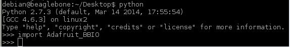
2. Hardware
- 1 x Linker kit base shield for Beaglebone
- 1 x Linker LED
- 1 x Linker Button
- 1 x Linker Potentiometer
- 1 x Linker cable
-
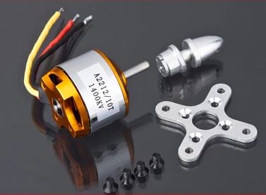
kV refers to R.P.M./Volt. It is how motors are rated, and does not mean KiloVolts. If we have a 12V electronic speed controller (ESC), the speed will be 12 times that number.
The higher the kV rating the faster the R.P.M of the motor. The lower the turns, the higher the R.P.M. of the motor.
3.5T means 10,500 RPM.
4.5T means 9,000 RPM.
5.5T means 7,400 RPM.
6.5T means 6.400 RPM.
7.5T means 5,800 RPM.
8.5T means 5000 RPM.
10.5T means 4,200 RPM.
13.5T means 3,300 RPM.
17.5T means 2,200 RPM.
21.5T means 1,800 RPM. -
3D printing is a quickly expanding field, with the popularity and uses for 3D printers growing every day. 3D printing can be used to prototype, create replacement parts, and is even versatile enough to print prostheses and medical implants. It will have a growing impact on our world, as more and more people gain access to these amazing machines.
For normal 3D printer, you need to have a PC connected to it. In this tutorial, we are going to cover how to use pcDuino act as host controller, and install 3D printer control software on pcDuino.
1.Install dependent software tools
Run the following commands in sequence:
“$sudo apt-get install git”
“$sudo apt-get install mercurial”
“$sudo apt-get install python-distribute”
“$sudo easy_install pip”2.Install WXWIDGETS
- Input command :“$curl http://apt.wxwidgets.org/key.asc | sudo apt-key add –”
(If it prompted that there is no such command as ‘curl’, please install it first using “$sudo apt-get install curl”)
- Edit “/etc/apt/sources.list”
Add the following content to it and save.
“# wxwidgets/wxpython repository at apt.wxwidgets.org
deb http://apt.wxwidgets.org/ dist-wx main
deb-src http://apt.wxwidgets.org/ dist-wx main“- Run the following commands in sequence:
“$sudo apt-get update”
“$sudo apt-get install python-wxgtk2.8”
“$sudo apt-get install python-wxtools”
“$sudo apt-get install libwxgtk2.8-dev”
“$sudo apt-get install libgtk2.0-dev”
3: Install driver for PYTHON serial port
“$sudo pip install pyserial”
“$sudo apt-get the install wx-common”
4: Install the required TK library for PYTHON“$sudo apt-get install python-pmw”
“$sudo apt-get install python-imaging”
5: Download PRINTRUN and related softwares
“$git clone https://github.com/kliment/Printrun.git home/Printrun”
Download the latest version skeinforge from http://fabmetheus.crsndoo.com/, and create a folder named “skeinforge” under directory “Printrun”, and unzip the just downloaded package into this directory. -
We are going to turn pcDuino into a digital picture frame.
The thing to make this magic happen is a tool called fbi: frame buffer interface.
To install the Linux Frame Buffer Interface using: $sudo apt-get install fbi.
To show the pictures, use the following command:
1$sudo fbi -noverbose -m 1920x1080 -a -T2-t10*.jpgThe mode supported by ‘-m’ can be found at:
1$more /etc/fb.modesThe switch ‘-T” means that displaying the pictures to HDMI, i.e., ‘-T 2′.
‘-a’ means that it will automatically fit the picture into the screen.
‘-t’ is the interval to change to picture.
-
LinkSprite has a clear enclosure that can be used for Arduino family and pcDuino V1.
To use this clear enclosure for pcDuino v2 requires the modification of the two ends.


The detail can be found at:
-
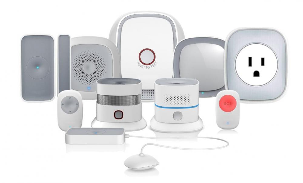
 Home automation is a hot topic AGAIN recently. Among the many open source solution, we choose openHAB. The openHAB project is aimed to provide the general platform for home automation. openHAB can run perfect on the pcDuino platform, can be used to DIY smart home project. pcDuino serves as the server/gateway in the whole system. The remote client node uses the STM8L Low Power Microcontroller, which is a custom designed MCU board. They communicates to the pcDuino OpenHAB server using the low power WiFi module ESP8266 Serial WIFI Module. In this particular project, we implemented a remote client that detects the status of the door status using a door status contact sensor. It senses the status and communicate the current state to pcDuino through the WiFi, and then pcDuino pushed the data using mqtt to openHAB server that resides on pcDuino. The openHAB server will then update the status on the mobile side. We also implement the other way around. We press a button on the mobile APP, and then openHAB will push a message to the remote node to turn on a LED. The mobile APP can be downloaded form Android or Apple app store by searching for ‘openhab’.
First we need to install the openHAB relate software, the detail can refer to LinkSprite Learning Center: http://learn.linksprite.com/?s=openhab
If you do not want to install yourself. Please download the install the the image that we prepare for you (openHAB was installed under under the /opt/openhab Directory) ;
http://pan.baidu.com/s/1ntHtCyX?qq-pf-to=pcqq.c2c Extraction code:fh6c
-
This scratch IO shield kit is designed by https://scratch-io.wikispaces.com.
The simple board is easy to solder and is then ready to use in an infinite number of projects. It contains some analog sensors onboard: light sensor, temperature sensor an angle sensor (potentiometer); some digital sensors: two push buttons. Also included, as digital output, a bi-color LED and analog power driver base on NPN transistor.
There is a full range of connectors where you can plug your own sensors and actuators. This tool it is perfect for programing students, and Robotic workshops. It has been designed by teachers of the Robotics lab of Colegio San Gredos in Alcalá de Henares, Madrid, Spain. It has been developed under the OpenHardware spirit, and it is given to the community to enjoy and to be improved. This scratch_io hardware runs linked to a Scratch modification made by S4A group from citilab (free downloadable). The standard Scratch version from MIT does not support it (soon, we expect it will be supported).
Let´s teach young people how to discover hardware and robotics in a friendly manner, let’s teach them how to build a better future.
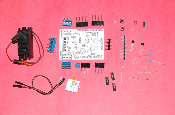
- Parts List
- Analog Input
- Digital Input
- Digital Output
- Analog Output
- Oops...
- Servo
- Revisit Analog Input
The following are included:
1. PCB
2. Components:
- 100nF C
- 10uF 5vol CAPAPOL
- D1 DOUBLE_LED Led bicolor
- K1 conector PCB con tornillo 3vias
- K2 conector PCB con tornillo 3vias
- P1 Tira pines simple 2,54mm (50pines)
- Q1 BC547
- R1 5k 1/4w
- R2 5k 1/4w
- R3 5k 1/4w
- R4 220ohm 1/4w
- R5 1K 1/4w
- RV1 POTENCIOMETER Vertical 10k
- SW1 SW_PUSH_SMALL. Pulsador para PCB
- SW2 SW_PUSH_SMALL. Pulsador para PCB
- TH1 LDR
- U1 Lm35
- Jumper 2,54… (4 units)
- Linker LED module
- RC continuous servo
-
1.Create bootable TF card for pcDuino8 Uno(Ubuntu)
There is no nand flash on pcDuino8 Uno, so it store the whole system on TF card.
If you want to install or refresh the Ubuntu system on pcDuino8 Uno, you can just take the following steps to create the bootable TF card for pcDuino8 Uno:
Pre-requisites
- 8G (or bigger) TF card( Speed class is recommended for Class 6 or higher)
- TF card reader
- Image for pcDuino8 Uno
- Windows tool: Win32DiskImager
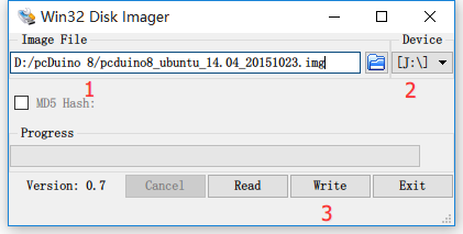
Create
Plug TF Card Reader into Windows PC and open Win32DiskImager as administrator.
- Select the Image File that you unzip from the downloaded File
- Select the Device that the PC recognized
- Click the write button.
- It will say Write Successful at the end.
Tips: If you only have Linux or Mac OS, how to create a bootable SD card? Only
ddcommand is needed.<code class="lang-bash">sudo dd <span class="hljs-keyword">if</span>=<image-file>.img of=/dev/sdb bs=<span class="hljs-number">1</span>M </code>
-
if=should be your downloaded system img file -
of=should be your micro-SD card.
Run
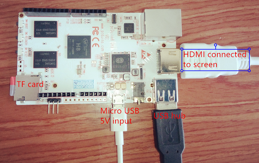
- Plug the TF card into pcDuino8 Uno
- Connect 5V DC power input via Micro USB port
- Connect keyboard and mouse with USB hub
- Connect screen with HDMI cable.
- Power on and run

Note: For the first time boot, system initialization may take some time (about 2-3 minutes ), and USB port is disabled. Please do not shutdown before system restart.
-
There is a debug port on pcDuino8 Uno which can used to access system directly as command line mode. You just only use a USB UART cable to connect to this port, when system is up, system initialization information will print to this port and also you can use it to log in Ubuntu. It seemly like an Linux terminal and you can control the whole system without screen, keyboard or mouse. Very convenient, isn’t it?
The following part will tell you how to use this debug port.
1. Get a USB UART cable

I use this PL2303 USB UART cable, and the details has been shown in the following table.
Color Description RED VCC BLACK GND GREEN TXD WHITE RXD 2. Install Drivers on PC(Windows as example)
Download the PL2303 Windows driver and install it.
3. Connect

One port of USB UART cable is connected to PC USB port。Another pins are connected to debup port on pcDuino8 uno.
debug port (RX) <—> RXD(WHITE)
debug port (GND) <—> GND(BLACK)
debug port (TX) <—> TXD(GREEN)4. Configure the Serial tool
Open Device Manager to get which COM port has been recognized by PC.
Open a serial tool(take Putty as example) and configure it:
Serial line :COM11
Speed:115200Then click “Open” button.
Power on pcDuino8 Uno, the log information will print on the window.
At the end, it directly login ubuntu as root, and you can input shell command to control the system.


Door Detector
in Theory articles
Posted
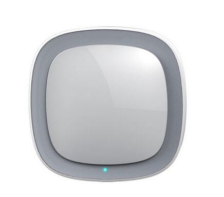
This is the Smart Door Sensor , adopts extra low power consumption ZigBee wireless module, long battery use life. Detect door or window's status by closing or opening magnet part with detector. Designed with double reeds, it can be used in different direction open doors or windows, easy installation and flexible to use. The product is suitable for residence, villa, houses, workshop, mall, warehouse, office building, bank and many other places for anti-burglar alarm. Smart Door Sensor
Features[edit]