

Ashish Adhikari
-
Posts
41 -
Joined
-
Last visited
-
Days Won
2
Content Type
Profiles
Forums
Events
Posts posted by Ashish Adhikari
-
-
A Gothic Lantern is a captivating piece of lighting that brings the allure of the Victorian Era into your home. The lantern is adorned with ornate top and bottom ornaments, reminiscent of the Gothic style that was prevalent during the Victorian Era.
My curiosity to create something new and interesting got me into this gothic style rechargeable lantern.
The design is both nostalgic and timeless, making the Gothic Lantern a perfect fit for homes that cherish a touch of historical charm.
Watch this video for detailed step by step instructions on how to build this lantern and for a complete instruction on how the electronic circuit works inside the lantern.
Downloading The STL Files

I went online and searched for a "Gothic Lantern" and found a very popular design by Shira.
The STL files were free to download from "Cults3D.com". It was literally a hard to resist 3D model. So, I went ahead and downloaded the lantern's STL files for my project.Modifying The STL Files
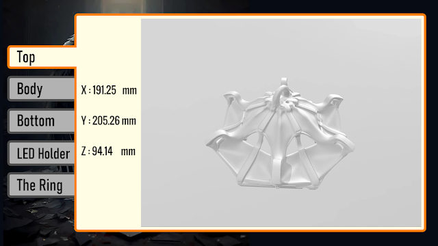
The downloaded STL files only comes with the top and the body of the lantern.
However, my aim is to add some electronics to the design to turn it into a rechargeable lantern. To achieve this, I created few more 3D models and added them to the design.
I created a base that can hold an "18650 battery holder" and an "USB Type-A charging cable".
I also created a "LED holder" that will go inside the body of the lantern. The LED holder has 10 x 5mm holes to hold the 10 white LEDs in it. It will also house the "TP4056 18650 Lithium battery charging module".
I also created a "ring" that will go on top of the lantern. Holding this ring, you can go anywhere with this lantern.
3D printing

Once the 3D models were sorted, it was time for me to fire up my 3D printing oven and start printing these 3D models.
I used:
- 1.75mm Cold White PLA Filament, and printed the models with
- 0.2mm
- with 0% infill
- and with support.
As we all know, 3D printing is the process that uses computer-aided design or CAD, to create objects layer by layer.
3D printing is not a new technology, its been there since 1980's, when Charles W. Hull invented the process and created the first 3D-printed part. Since then, the field of 3D printing has grown exponentially and holds countless possibilities. The 3D printing process fascinates me a lot and I sometimes love to sit near my printer and watch these layers getting printed.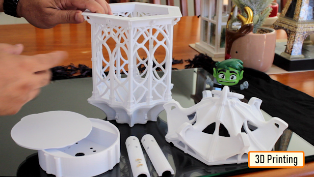
The entire printing process took a little over 53 hours and this was the final result.
Circuit Diagram

The circuit is very simple.
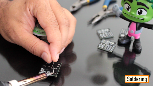
A USB Type-A charging cable connects to the input of the TP4056 Module. The 18650 Battery connects to the B+ and B- terminals of the module. And finally, the LEDs connect parallelly to the OUT+ and OUT- terminals of the module with a push button switch connected to the +ve terminal. Using this switch we can turn on or off the lantern.Soldering

Lets start by soldering the wires to the LEDs. As previously discussed, all these LEDs will be parallelly connected to each other.
Next, I screwed the 18650 battery holder to the base of the lantern. After that, I superglued one of the LED holders to the base, and then one by one slided the LEDs into the holes of the LED holder.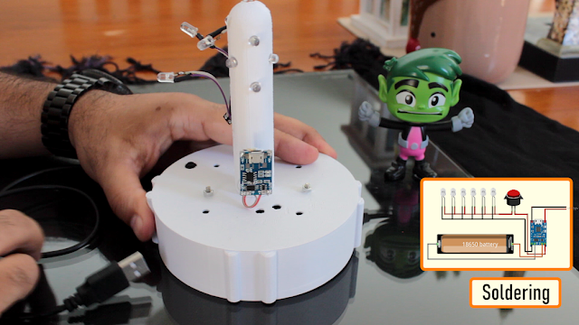
After that, I soldered the TP4056 module as per the circuit diagram. To conclude the setup, I pushed the remaining LEDs into the holes of the 2nd half of the LED holder and then superglued it to the base of the lantern.
Coloring

I wanted to give this lantern a "rustic wooden texture".
For that I applied acrylic "Raw Sienna" and "Burnt Umber" to the body of the lantern.Final Assembly

I wanted this lantern to have a soft illumination without any harsh light. So, I went ahead and used the white plastic of a milk bottle to give this lantern a defused lighting effect.
I used metal pieces and magnets to stick the bottom plate to the base of the lantern.
Once all the electronics bits were sorted, I screwed the body of the lantern to the base.
Then to conclude the setup, I superglued the top to the body of the lantern, that's it all done.Demo

So, this is how my final setup looks like.
The red glow inside the lantern (bit hard to see in the bright sunlight), indicates that the battery is charging.
Press the push button switch from the base of the lantern to turn it on or off.
Do comment, and let me know if there are any scopes of improvement.Thanks
Thanks again for checking my post. I hope it helps you.
If you want to support me subscribe to my YouTube Channel: https://www.youtube.com/user/tarantula3
Video: Visit
Full Blog Post: Visit
Solar Battery Charger: Video
Gothic Lantern STLs: Github
Model inframe: Instagram
Support My Work- BTC: 1Hrr83W2zu2hmDcmYqZMhgPQ71oLj5b7v5
- LTC: LPh69qxUqaHKYuFPJVJsNQjpBHWK7hZ9TZ
- DOGE: DEU2Wz3TK95119HMNZv2kpU7PkWbGNs9K3
- ETH: 0xD64fb51C74E0206cB6702aB922C765c68B97dCD4
- BAT: 0x9D9E77cA360b53cD89cc01dC37A5314C0113FFc3
- LBC: bZ8ANEJFsd2MNFfpoxBhtFNPboh7PmD7M2
- COS: bnb136ns6lfw4zs5hg4n85vdthaad7hq5m4gtkgf23 Memo: 572187879
- BNB: 0xD64fb51C74E0206cB6702aB922C765c68B97dCD4
- MATIC: 0xD64fb51C74E0206cB6702aB922C765c68B97dCD4
Thanks, ca gain in my next tutorial. -
The 555 timer IC is an integrated circuit (IC) that is used in a variety of timer, delay, pulse generator and oscillator circuits.
In this tutorial, I am going to show you guys how to make an "Adjustable Delay Timer Circuit" using the 555 timer IC. This circuit can automatically turn on/off any circuit after a fixed duration. This timer circuit is useful when you need to power On/Off any AC Appliances after a pre-defined duration. For example, you can use this circuit to automatically turn off a mobile charger after a certain period of time to avoid over charging, or you can turn on/off a light bulb after a certain period.
The time delay of this circuit can be adjusted by using various combinations of resistors and capacitors.
Watch this video for detailed step by step instructions on how to build this circuit and to know how this circuit works.Components Required

For this tutorial we need:- A 555 Timer IC
- A Push Button Switch
- A Red And A Green LED
- 2 x 220Ohm Current Limiting Resistors
- 1 x 10K Resistor
- A Breadboard and Few Breadboard Connectors
- A 5V Power Supply
- A 470uF Capacitor
- And Few Combinations Of Resistors Or A Potentiometer
555 Timer IC In Monostable Mode

Lets start by putting all the components together and lets understand how the circuit works.
In the first example, I am going to show you guys the "on-off timer circuit" with a fixed timing Resistor and Capacitor.
The heart of this circuit is the 555 timer IC.
Pin No.1 of the IC is connected to GND.
By connecting Pin 6 and 7 of the 555 timer IC, we put the IC in "Monostable Mode". In Monostable Mode, the output of the IC is stable in "One State", and it will always return to this state after a certain period of time when it gets pushed out of that state.
The output at Pin 3 of the 555 Timer IC in monostable mode is generally LOW - indicated by the green LED. When you trigger the circuit using the push button switch, the output goes HIGH - indicated by the red LED, for a certain period of time before it goes back to its LOW state.
The time the circuit stays HIGH is decided by the value of a resistor R1 and a capacitor C1. The higher the values, the longer it stays HIGH (On).
To adjust the timer duration "on-the-fly", the timing Resistor R1 can be replaced by a Potentiometer. By changing the value of the resistance of the potentiometer we can either increase or decrease the duration of the timer.Logic Using Circuit Simulation

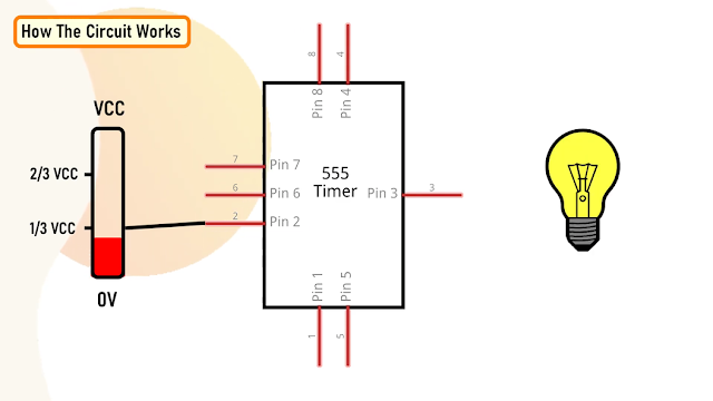
Alright, now I am going to explain how this circuit works with the help of an animation.- When Pin 2 of the IC detects voltage LESS than 1/3rd of the supply voltage, it turns ON the output on Pin3.
- And, when Pin6 detects voltage MORE than 2/3rds of the supply voltage, it turns OFF the output.
- Whenever the output of the IC is in OFF state, the Discharge Pin (Pin7) acts as ground, as it is internally grounded.
This is how the trigger pin (Pin2) and the threshold pin (Pin6) of the 555 timer IC sense voltages and controls the output at Pin3.
When we power on the circuit, the output is in OFF state. Hence, the discharge pin (Pin7) will be internally grounded discharging the capacitor.
Pressing the push button switch activates the delay timer and the following sequence starts:- Trigger Pin (Pin2) gets grounded
- Since this applied voltage at Pin2 (0V) is less than 1/3rd of the supply voltage (5V), the output at Pin3 turns ON
- And at the same time, the Discharge Pin (Pin7) disconnects internally from 0V
- This causes the capacitor to charge via the resistor or potentiometer
- Now, the voltage across Pin6 starts increasing
- As soon as the capacitor charges to 2/3rds of the supply voltage, Pin6 turns OFF the output
- When the output turns OFF, Pin7 gets internally grounded discharging the capacitor.
The above steps are repeated each time you push the push button switch.
The time period for which the capacitor charges from 0V to 2/3rds of supply voltage is the "delay time".
Calculations
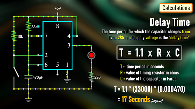
A discussed earlier, the time period for which the capacitor charges from 0V to 2/3rds of supply voltage is the "delay time".
We can calculate this time using the formula: T = 1.1 * R * C
Where T is the time period in seconds, R is the value of timing resistor in ohms and C is the value of the capacitor in Farad.
In the previous example we used a 33K resistor and 470uF capacitor which gives us a delay period of:
T = 1.1 * (33000) * (0.000470) = 17 seconds.The Board

To make things easy, I designed a PCB for this setup.
So, this is how my PCB looks like in 2D and 3D.
You can either add a resistance or a potentiometer to the board to control the delay time.
I have created 2 versions of this board:
V1: Without A Relay Module
V2: With A Relay Module
Using the board with the relay module, you can control other DC Circuits or AC Appliances.
For a quick reference, I added the delay period calculator on the board.
Soldering

Alright, now, lets solder the components to the board.
In this setup, I am going to solder a potentiometer to the board and hence I will leave the resistor bit as is.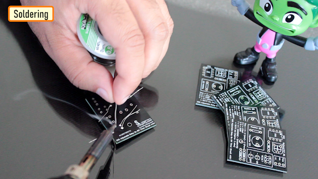
So, lets start by soldering all the resistances to the board.
Then, lets solder the LEDs to the board followed by the Push Button Switch.
After that, lets solder the IC base and the capacitor to the board.
As discussed earlier, instead of the resistor I am soldering a Potentiometer to the board.
To finalize the setup, I am soldering few male pin headers to the board, that's it all done.
The 2nd version of the board with the relay module looks like this.
Demo

For the demo purpose, I am going to use the board that has the relay module on it.
Using this board, I can demo both the operation of the relay and the LEDs.
Lets set the resistance of the potentiometer to a desired value and then lets do the quick math to see how long this circuit will stay on.
Alright, now that we have all the values, lets start the timer on my mobile and press the push button switch both at the same time.............
Bingo, mission accomplished.
You can use the relay in either NC or NO state in your project.
Uses

This Delay Timer Circuit can be used as a:
- Timer for any robotics project
- Turning off mobile chargers to prevent overcharging
- Turning On/Off lights automatically after a set duration
- In Auto power On/Off circuits using Relays and more..
The possibilities are endless..
Thanks
Thanks again for checking my post. I hope it helps you.
If you want to support me subscribe to my YouTube Channel: https://www.youtube.com/user/tarantula3
PCBWay 6th Project Design Contest: https://www.pcbway.com/activity/6th-project-design-contest.html
Support My Work- BTC: 1Hrr83W2zu2hmDcmYqZMhgPQ71oLj5b7v5
- LTC: LPh69qxUqaHKYuFPJVJsNQjpBHWK7hZ9TZ
- DOGE: DEU2Wz3TK95119HMNZv2kpU7PkWbGNs9K3
- ETH: 0xD64fb51C74E0206cB6702aB922C765c68B97dCD4
- BAT: 0x9D9E77cA360b53cD89cc01dC37A5314C0113FFc3
- LBC: bZ8ANEJFsd2MNFfpoxBhtFNPboh7PmD7M2
- COS: bnb136ns6lfw4zs5hg4n85vdthaad7hq5m4gtkgf23 Memo: 572187879
- BNB: 0xD64fb51C74E0206cB6702aB922C765c68B97dCD4
- MATIC: 0xD64fb51C74E0206cB6702aB922C765c68B97dCD4
Thanks, ca gain in my next tutorial.
Tags
----
on-off timer circuit, Adjustable Delay Timer Circuit, 555 Timer Project, Breadboard Demo, Monostable Mode, astable mode, bistable mode, one-shot circuit, Circuit Simulation, relay Module NC. relay Module NO, 555 Adjustable Delay On Off Timer Circuit, circuit diagram, 555 IC, adjustable on off relay module, delay timer, time delay relay, off delay timer,
Odysee: https://odysee.com/@Arduino:7/555-Adjustable-Delay-On-Off-Timer-Circuit:2
Cos: https://cos.tv/videos/play/48667261956559872
Rumble: https://rumble.com/v3w7p5k-555-adjustable-delay-on-off-timer-circuit.html -
-
When the full moon is shining and the wolves are howling, it's time for Halloween's spooky spectacle. The snickering grins of jack-o'-lanterns glow from lit porches. Kids skip down the block in spooky costumes, carrying bags full of candy and shouting "Trick or Treat!". The Nightmare Before Christmas is almost here...
Do you see dead people???
Alright Enough of that, in this Spooktacular video I am going to create an Arduino based 3D printed Halloween Décor.
It's super easy, fun and spooky....
3D Printing

3D Printing is a highly addictive hobby! This is the very first time I am using my 3D printer to print something electronics related. The STL files used in this project are all downloaded from www.Thingiverse.com. I have uploaded a copy of all the 3D Objects to my GitHub repository, the link is in the description below.
 3D printing has changed my life. There are so many things you can do using a 3D printer. From designing 3D Models to printing them using the 3D printer has now become my new hobby. I've been a "maker" since I was 10 years old, and have always constructed and made my own stuff. 3D printing for me is a blessing. I am totally lost in the 3D printing heaven.
3D printing has changed my electronics workshop life forever. Before when I used to order parts, I always used to wonder if the parts would fit into my projects resources... but after I got my 3D printer... it doesn't matter at all, because if it doesn't fit - I could design and print it myself. The 3D printer was definitely "The Missing Piece" from my electronics workshop.
Schematic Diagram
 Now that we have all our 3D Models printed, lets have a look at the component assembly.
The assembly is super simple. We just need to connect 4 Yellow LEDs to D2, D3, D4 and D5 pins of Arduino via 220ohm current limiting resistor.
Then connect the white LED to Analogue Pin D10 of the Arduino via a current limiting resistor.
That's it, as simple as that.
The Code
 Now, lets have a look at the code that will drive the LEDs.
Lets start by defining all the variables.
Then in the setup section lets define all the pin modes.
To flash the LEDs I chose 5 different Flashing patterns:
1. All LEDs Flash Very Fast For 10 Seconds
2. All LEDs Flash Slowly For 10 Seconds
3. 2 LEDs Turn On and 2 LEDs Turn Off for 10 seconds
4. LED Chaser Circuit for 10 seconds
5. One LED Randomly Turn On for 10 seconds
The switch statement in the loop() section randomly picks up one of these patterns and runs it for 10 seconds.
The white LED also fades in and out after every cycle.
At the bottom of the code, I have defined all these 5 LED flashing patter in their respective functions.
Demo on Breadboard
 After loading the code on an Arduino Nano this is how it looks like.
The white LED will go inside the Ghost and the Yellow LEDs will go inside the Pumpkins.
Humm, that looks promising, isn't it?
Assembling
 Let's start by soldering the wires to the LEDs.
Then lets solder the Arduino Nano to a perf-board and then solder all the resistors to the board.
Next, lets soldered the LEDs to the D2, D3, D4, D5 and D10 pins of the Arduino via the current limiting resistors.
That's all you have to do for the electronics bit. Now, let's hot glue the perf-board inside the coffin, followed by all the LEDs to a wooden block.
Before putting the 3D printed components on the LEDs, let's do a quick test to verify everything works as expected. Look at that...
Now, one by one lets hot glue the 3D printed components to the plank. To finalize the setup, I added a few dry grass leaves to hide the wirings. That's it all done.Final Demo
 So this is how my final setup looks like.
Do comment and let me know if there are any scopes of improvement. Until then, Happy Halloween....
Thanks
Thanks again for checking my post. I hope it helps you.
If you want to support me subscribe to my YouTube Channel: https://www.youtube.com/user/tarantula3
STL Files:
Support My Work
- BTC: 1Hrr83W2zu2hmDcmYqZMhgPQ71oLj5b7v5
- LTC: LPh69qxUqaHKYuFPJVJsNQjpBHWK7hZ9TZ
- DOGE: DEU2Wz3TK95119HMNZv2kpU7PkWbGNs9K3
- ETH: 0xD64fb51C74E0206cB6702aB922C765c68B97dCD4
- BAT: 0x9D9E77cA360b53cD89cc01dC37A5314C0113FFc3
- LBC: bZ8ANEJFsd2MNFfpoxBhtFNPboh7PmD7M2
- COS: bnb136ns6lfw4zs5hg4n85vdthaad7hq5m4gtkgf23 Memo: 572187879
- BNB: 0xD64fb51C74E0206cB6702aB922C765c68B97dCD4
- MATIC: 0xD64fb51C74E0206cB6702aB922C765c68B97dCD4
Thanks, ca gain in my next tutorial. -
Proximity sensing is a very common application in electronics.
There are several ways to accomplish this. The most common way is by using a PIR sensor. PIR Sensor senses the change in ambient infrared radiation caused by warm bodies. I have already covered this in my Tutorial No. 5: "PIR Sensor Tutorial - With or Without Arduino". However, since PIR sensors detect movement from living objects, they can generate false alarms. These sensors are also inefficient in hot environments, as they rely on heat signatures.The other common methods of proximity sensing involve, using reflected ultrasonic or light beams. Using these sensors, the intruding object is detected by the reflected beam back to its source. The time delay between transmission and reception is measured to calculate the distance to the object.
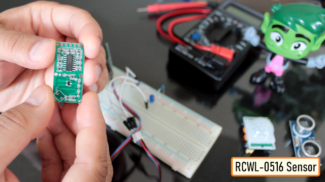
In this tutorial, we are going to look at another method of proximity sensing using "Microwaves" and "Doppler Effect". In my hand is an inexpensive RCWL-0516 Microwave Radar Motion Sensor. The RCWL-0516 microwave sensor detects "any movement" from "any object" and does not rely on heat, making it more reliable in hot environments. I am going to use this sensor to create a Geo-fence around my house to detect motion and get notifications.
What is the Doppler effect?
.png)
The RCWL-0516 module uses a “Doppler Radar” that makes use of the "Doppler Effect" to detect motion and trigger proximity alerts.
So, before understand how the RCWL-0516 sensor works, let’s understand the Doppler Effect.

The Doppler effect, is named after the Austrian physicist Christian Doppler, who described this phenomenon in 1842.
He described the change in frequency observed by a stationary observer when the source of the frequency is moving. The sound's pitch is higher than the emitted frequency when the sound source approaches the observer as the sound waves are squeezed into shorter distance (bunched together), which can be heard as a higher pitch. The opposite happens when the object moves away from the observer, causing the sound waves to become lower in frequency and lower in pitch (spread out). As a result, the observer can hear a noticeable drop in the pitch as it passes.
This holds true for all sorts of waves, such as water, light, radio, and sound.How Does The RCWL-0516 Works?
Like the PIR Sensors, these sensors also detects only movements within their detection range. But instead of sniffing the blackbody radiation of a moving object, these sensors uses a “Microwave Doppler Radar” technique to detect a moving object.
Doppler microwave detection devices transmit a continuous signal of low-energy microwave radiation at a target area and then analyze the reflected signal. The target’s velocity can be measured by analyzing how the target’s motion altered the frequency of the transmitted signal..png)
Due to Dopplers effect, the frequency of reflected microwave signal is different from the transmitted signal when an object is moving towards or away from the sensor. When a car approaches a speed trap radar, the frequency of the returned signal is greater than the frequency of the transmitted signal, and when the car moves away, the frequency is lower. This is how a speed gun calculates the speed of the car.Technical Specifications

The technical specifications of this sensor are listed below:
- Operating Voltage: 4-28V (typically 5V)
- Detection Distance: 5-7 Meters
- Maximum Current Drawn: ~ 2.7 mA
- Operating Frequency: ~ 3.18 GHz
- Transmission Power: 20 mW (typical)/30 mW (max)
- Signal length: ~ 2s
- Regulated Output: 3.3V, 100mA
RCWL-0516 Module Pin outs
 The RCWL0516 module is a single breakout board with the following connections:
3V3 : it is the "output" from the onboard 3.3V regulator which can be used to power external circuits. Remember, this is not an input pin. This pin can provide up to 100mA of current.
GND : is the ground pin.
OUT : is the 3.3V TTL logic output. This pin goes HIGH for 2seconds when a motion is detected and goes LOW when no motion is detected. The output of this module is "analog" and can be connected to an analog input of a micro controller and sampled by an ADC. The output voltage is roughly proportional to the distance between the sensor and the object.
VIN : provides power to the module. Connect this pin to an input voltage anywhere between 4 to 28V (however, 5V is commonly used). This module consumes less than 3mA of current so, you can easily power this by the 5V output from an Arduino or a Raspberry Pi.
CDS : pins are where you attach an optional LDR (light dependent resistor) allowing it to operate only in the dark.
You can connect the LDR to the sensor in two ways:
* By using the two CDS pads on the top of the module.
* Or by connecting one end of the LDR to the CDS pin at the terminal end, and the other end to the ground.
We will cover this in the details in the demo section.
Remember, this module comes without any connecting pins attached to it.
What does CDS stand for?
CDS stands for Cadmium Sulphide, which is the photoactive component in LDRs. Because of this, LDRs are sometimes called CDS photoresistors.
The RCWL-9196 IC
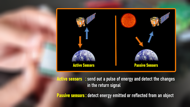 Unlike the PIR sensor, this is an active sensor (Active sensors send out a pulse of energy and detect the changes in the return signal). The module sends out microwaves signals actively at a frequency of about 3.18 GHz and measures the reflected signals. The heart of the module is a doppler radar controller IC "RCWL-9196". This IC is very similar to the BISS0001 IC found in the PIR sensors.
The chip also supports "repeat triggers" and has a "360-degree detection area without blind spots".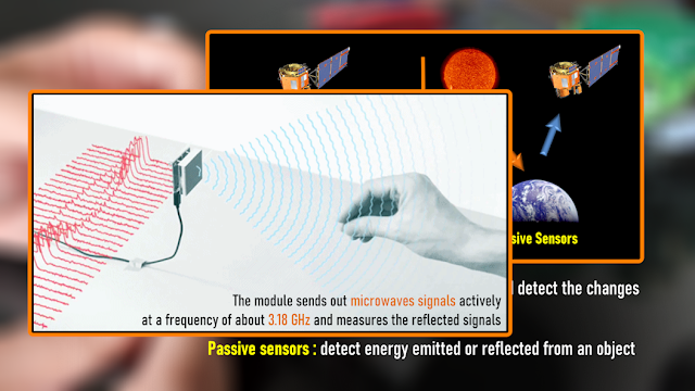
Microwave Antenna and RF Power Amplifier

The MMBR941M RF amplifier is a high-speed NPN transistor "Q1" that takes low-power RF signal and boosts it to a higher power level. The antenna is integrated on the PCB. It has a detection range of approximately "7 Meters" while only consuming less than "3mA of current". When triggered, the output (OUT) pin will switches from LOW (0V) to HIGH (3.3V) for 2 to 3 seconds before returning to its idle (LOW) state.
The transistor Q1 also acts as a mixer that combines the transmitted and received signal and outputs the difference which is filtered by the low pass filter formed by C9 and R8, and is amplified by the IC.Jumper Settings
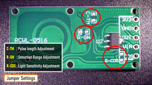
The module has 3 jumper settings at the back of it. The sensors default settings can be altered, by populating these jumpers with appropriate resistors and capacitors:
C-TM : (Pulse length Adjustment) By installing a suitable SMD capacitor you can adjust the repeat trigger time by extending the output pulse length. Default trigger time is 2s. Increasing capacitor's capacity will make repeat trigger time longer. A 0.2µF capacitor extends the output pulse to 50s, while 1µF extends it to 250s.
R-GN : (Detection Range Adjustment) By installing a suitable resistor you can reduce the detection range. The default detection range is 7m. If you install a 1M resistor the distance reduces to 5m, while a 270K resistor reduces it to 1.5m.
R-CDS : (Light Sensitivity Adjustment) You can use this as an alternative to soldering the LDR. Any resistor between 47K – 100K will suffice. The lower the value, the brighter the light must be in order to disable the trigger.Demo
Demo 1: Basic Setup
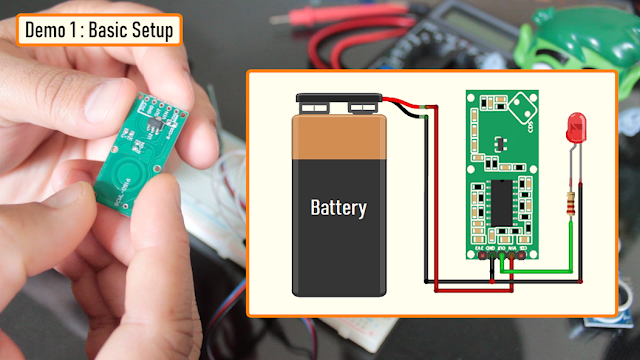
This sensor is capable of working on its own even without a microcontroller. In my first example I am going to show you guys how useful it is on its own.
The wiring is very simple, you just need to connect the sensor's VIN and GND to a power supply between 4-28V. Then connect a LED to the OUT pin via a 220Ω current limiting resistor. That’s it, as easy as that.
Now, when the module senses motion, the red LED lights up for about two seconds when the OUT pin of the sensor goes “HIGH”. You can replace the LED with a relay module if you want to turn something ON/OFF based on motion.Demo 2: Connecting an LDR
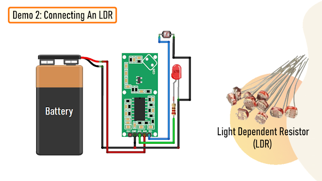 The setup is exactly same as the previous one with an addition of an LDR.
As discussed earlier, you can either connect the LDR to the two CDS pads on the top of the sensor, or attach one leg of the LDR to the CDS pin at the bottom of the module and the other one to GND. LDRs don't have polarity, so they can be connected in any direction of your choice.

When the LDR is exposed to light the resistance of the LDR decreases, and you will notice that the sensor produces no output. However, the sensor resumes normal operation once the room is darkened.
This property of the sensor can be used in spotting intruders at night or controlling lights in a room.Demo 3: Connecting an Arduino
 While this module works well on its own, it also works well as a sensor when hooked up to a microcontroller or a microcomputer.
In this example, I am going to light up an LED using an Arduino when the sensor senses a motion.

Power the sensor from the 5v pin of the Arduino and connect the OUT pin to pin 2 of the Arduino.
Now, connect an LED to pin no 3 of the Arduino via a 220Ω current limiting resistor.
Upload the code and swipe your hand over the sensor. The red LED lights up and the serial monitor displays the message "Motion Detected" when the sensor detects a motion.Demo 4: Sending Motion Alerts Over RF or WiFi

You can do all sorts of funky stuff using this sensor.
You can attach this module to a nodeMCU or a NRF20L01 transceiver module or to a 433MHz RF transmitter/receiver module to send the detected motion information as a notification to a mobile device or save it in a database.
Advantage and Disadvantages
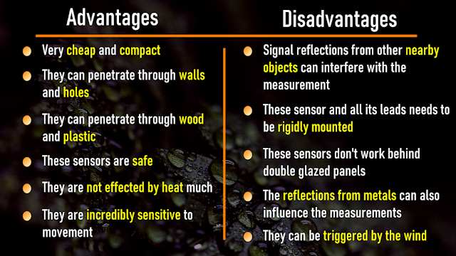
Advantages- Very cheap and compact. The PCB itself is less than 4mm thick
- They can penetrate through walls and holes allowing them to have a wide detection range
- Radar signals can penetrate non-conductive materials such as plastic and wood allowing them to be hidden or protected from accidental damage
- These sensors can work perfectly behind 18mm thick pieces of pine wood, 50mm thick hardback book with no obvious reduction in sensitivity
- These sensors are safe. They put out very low levels of microwaves at 3.2GHz
- They are not effected by heat much and have better detection rate than traditional IR sensors
- They are incredibly sensitive to movement and can detect small movements very easily
Disadvantages
- Since these sensors rely on a Doppler radar system, signal reflections from other nearby objects can interfere with the measurement, making it less reliable and accurate than other sensors
- These sensor and all its leads needs to be rigidly mounted. If the connecting leads are subject to movement or vibration, they will trigger the sensor
- These sensors don't work behind normal standard double glazing panels
- The reflections from metals can also influence the measurements
- They can be triggered by the wind
- You can use Aluminum foils to block the microwave signals from the sensor
Uses
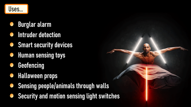
- Burglar alarm
- Intruder detection
- Smart security devices
- Human sensing toys
- Geofencing
- Halloween props
- Sensing people/animals through walls even without light
- Security and motion sensing light switches
Thanks
Thanks again for checking my post. I hope it helps you.
If you want to support me subscribe to my YouTube Channel: https://www.youtube.com/user/tarantula3Other Links:
- PIR Sensor Tutorial - With or Without Arduino: YouTube
- DIY Relay Module: YouTube
- All About nRF24L01 Modules: YouTube
- DIY - NodeMCU Development Board: YouTube
- Contactless Wireless Door Bell Using Arduino: YouTube
- Doppler Effect: Wikipedia
Support My Work
- BTC: 1Hrr83W2zu2hmDcmYqZMhgPQ71oLj5b7v5
- LTC: LPh69qxUqaHKYuFPJVJsNQjpBHWK7hZ9TZ
- DOGE: DEU2Wz3TK95119HMNZv2kpU7PkWbGNs9K3
- ETH: 0xD64fb51C74E0206cB6702aB922C765c68B97dCD4
- BAT: 0x9D9E77cA360b53cD89cc01dC37A5314C0113FFc3
- LBC: bZ8ANEJFsd2MNFfpoxBhtFNPboh7PmD7M2
- COS: bnb136ns6lfw4zs5hg4n85vdthaad7hq5m4gtkgf23 Memo: 572187879
- BNB: 0xD64fb51C74E0206cB6702aB922C765c68B97dCD4
- MATIC: 0xD64fb51C74E0206cB6702aB922C765c68B97dCD4
Thanks, ca gain in my next tutorial. -
16 hours ago, bidrohini said:
You did a lot of hard work I must say. For this type of fading effect, I always use Arduino or AVR microcontroller. It is very easy to do this with the PWM pins of the Arduino. But making the project this much compact and without programming really needs good skills. Good work.
Thanks mate
On 5/28/2023 at 7:30 PM, Satyadeo Vyas said:Hi Ashish,
Nicely explained ... I love reading your article
-
Thanks a lot mate
-
It's been a while, the Autobots have appeared on the silver screen. Finally they are returning to the big screen in their upcoming Transformers movie "Rise of the Beasts".This inspired me in making a PCB Badge to complement my enthusiasm and love towards the Autobots.In this tutorial, I am going to show you guys how to design this "Transformers PCB Badge" and how to solder the components to it.
Components Required
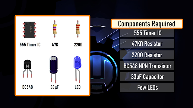
For this tutorial you need:- 1 x 555 Timer IC
- 1 x 47KΩ Resistor
- 1 x 220Ω Resistor
- 1 x BC548 NPN Transistor
- 1 x 33µF Capacitor, and
- 1 x Few Blue LEDs
Quick Recap
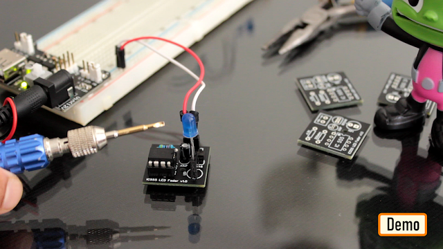
In my last tutorial I created a "IC555 Led Fader Module" and explained how the circuit works. In this tutorial, I am going to use the same LED fader circuit to create a fading effect for the eyes of the badge.So before going ahead, lets do a quick recap and find out how the LED fader circuit works with the help of an animation.Circuit Diagram
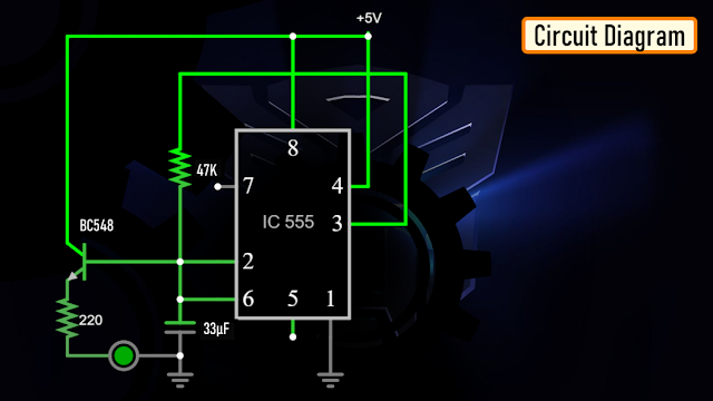
The heart of this circuit is the 555 timer IC.Pin No.1 of the IC is connected to GND.By connecting Pin 2 and 6 of the 555 timer IC, we put the IC in astable mode. In astable mode, the 555 timer IC acts as an oscillator (re-triggering itself) generating square waves [PWM Signals] from the output Pin no. 3.3 other components connect to this junction.1st one is the 33µF capacitor. The positive pin of the capacitor connects to the junction and the negative pin is connected to the GND.2nd one is the 47KΩ resistor. One of its legs connects to the junction and the other leg connects to the Output pin, Pin No.3 of the IC.3rd one is the Base of the BC548 NPN transistor. The collector of the transistor along with Pin 8 and 4 of the IC connects to the +ve terminal. of the battery. The LED along with its current limiting resistor is connected to the Emitter of the transistor.That's+-How The Circuit Works
- When Pin 2 of the IC detects voltage LESS than 1/3rd of the supply voltage, it turns ON the output on Pin 3.
- And, when Pin 6 detects voltage MORE than 2/3rds of the supply voltage, it turns OFF the output.
This is how the trigger pin (Pin2) and the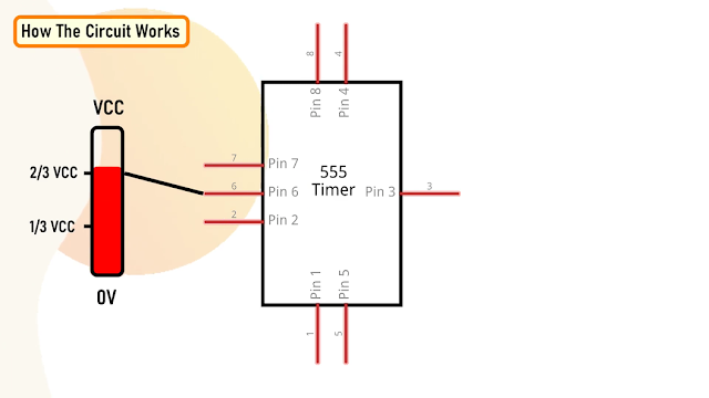
threshold pin (Pin6) of the 555 timer IC sense voltages and controls the output at Pin 3.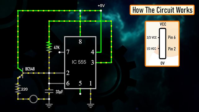
- The Capacitor attached to the circuit will be in a discharged state immediately after firing up the circuit.
- So, the voltage at Pin 2 will be 0v which is less than 1/3rds of the supply voltage, this will turn ON the output on Pin 3.
- Since Pin 3 is looped back to Pin 2, it will start charging the Capacitor via the 47KΩ resistor.
- At the same time the base current of the transistor also increases causing the LED to slowly "fade-in".
- Once the voltage across the capacitor crosses 2/3rds of the supply voltage, Pin 6 turns OFF the output.
- This causes the capacitor to slowly discharge causing the base current to fall and hence the LED starts "fading-out".

- Once the voltage across the capacitor falls below 1/3rd of the supply voltage, Pin 2 turns ON the output, and the above cycle continues.
You can hook up a multimeter to the circuit to measure the charging and discharging of the capacitor.Designing The PCB
Sorting Out Images
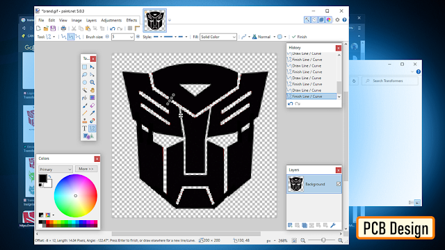
To start the designing process, I need a transparent PNG image of the "Transformers Logo".So I went online, and did an "image search" and downloaded a black-and-white images of the Transformers Logo.Now, using the "Paint.Net" application I opened up the PNG file.The image onscreen will be used for:1. Creating the border outline of the badge2. and also for creating the face on top of the top silk layerTo generate the "Border Outline" I need a DXF file.Looking at the image, we can see that the image is split into multiple parts. If I load this to generate a DXF file it will generate multiple pieces of the PCB. And obviously that's not what I am after. So, I joined all the small pieces into a single image.Generating DXF File

Then, I uploaded the images to "https://convertio.co/" to generate the DXF files. This website allows 10 free conversions in a day unless you have a paid account with them.Creating the Badge
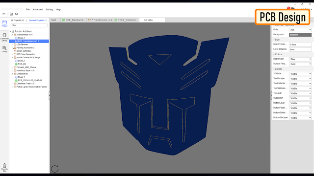
Now, lets go ahead and add a "New PCB" to our project and remove the default board outlines.Then import the DXF files via File > Import > DXF menu. Make sure you have the "BoardOutLine" selected under layers when you import the DXF file.Now, lets import the image that will go on the Top Silk Layer. Select the "TopSilkLayer" and then import the image and move it inside the board outlines. Before going ahead, lets have a look at how the board looks like in 3D. As we can see the eyes and all other holes still have the blue PCB bits inside. So, let go ahead and remove them from our design.To do so, select the "MultiLayer" from the "Layers and Objects" panel. Then select "Solid Region" from the "PCB Tools" panel and start drawing the region you want to exclude from your PCB. That's it as easy as that. Checking the PCB in 3D, we can see that the top bit has now a see-through hole in it. I repeated this step, for all other bits that I wanted to excluded from my PCB design.Once the PCB design was sorted, I added all the electronic components to the board. Since I don't want any hole on my PCB, my choice was to either add SMD components on the board or to design the board in a way that I can solder THT components on it. I chose the second option and added all the THT components "however" without their holes. Instead of the holes I added some rectangles and circles from the "PCB Tools" panel on the "BottomLayer" and then exposed the copper. To finalize the design, I connected all the exposed pads as per the circuit diagram. That's it, all done. So, this is how the final design looks like.The Board

So this is what came in the mailbag. Have a look at the quality, its absolutely mind-blowing.At the back of the board are all the exposed copper parts for soldering the electronic components.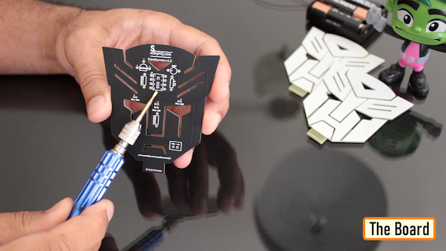 As mentioned earlier, I could have designed the board with SMD components, however I wanted to design something that someone with "0" SMD soldering knowledge can also do.
Soldering

Alright, now lets go ahead and solder the components to the board.Lets first soldered the 555 Timer IC to the board, then lets soldered the two resistors to the board. Next, lets soldered the 33µF Capacitor followed by the NPN transistor to the board.To conclude the setup lets soldered the 2 x LEDs to the board. You can power this circuit by providing voltage between 5V to 15Vs.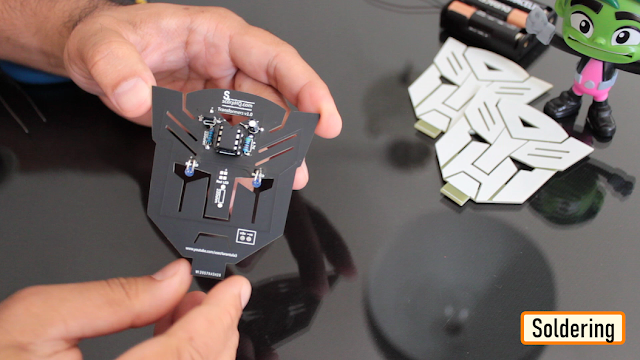
Demo

So, this is how the final setup looks like. You can insert the bottom bit of the badge to a wooden-plank and put this on your desk to give your desk a flashy look.Thanks
Thanks again for checking my post. I hope it helps you.If you want to support me subscribe to my YouTube Channel: https://www.youtube.com/user/tarantula3Support My Work:- BTC: 1Hrr83W2zu2hmDcmYqZMhgPQ71oLj5b7v5
- LTC: LPh69qxUqaHKYuFPJVJsNQjpBHWK7hZ9TZ
- DOGE: DEU2Wz3TK95119HMNZv2kpU7PkWbGNs9K3
- ETH: 0xD64fb51C74E0206cB6702aB922C765c68B97dCD4
- BAT: 0x9D9E77cA360b53cD89cc01dC37A5314C0113FFc3
- LBC: bZ8ANEJFsd2MNFfpoxBhtFNPboh7PmD7M2
- COS: bnb136ns6lfw4zs5hg4n85vdthaad7hq5m4gtkgf23 Memo: 572187879
- BNB: 0xD64fb51C74E0206cB6702aB922C765c68B97dCD4
- MATIC: 0xD64fb51C74E0206cB6702aB922C765c68B97dCD4
Thanks, ca again in my next tutorial. -
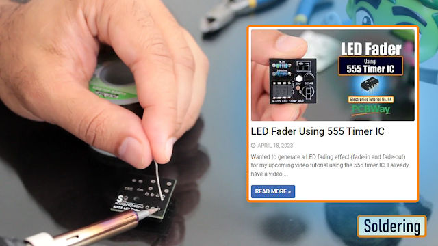
Wanted to generate a LED fading effect (fade-in and fade-out) for my upcoming video tutorial using the 555 timer IC.I already have a video where I used LM358 Dual Operational Amplifier IC and another one with Arduino to generate the LED fading effect.YouTube, is full of video showing how to generate the fading effect using 555 timer IC. However, none of them produce a true fading effect.Some just fades-in but never fades-out. And there is literally no explanation of how they are generating the fading effect other than just showing how to assemble the components.In this tutorial, I am going to show you guys how to create a true LED fading effect using the 555 timer IC. I will also explain how the circuit works and how changing components change the fading effect of the LEDs.
Components Required
 For this tutorial you need:1 x 555 Timer IC1 x 47KΩ Resistor1 x 220Ω Resistor1 x BC548 NPN Transistor1 x 33µF Capacitor, and1 x Few Blue LEDs
Circuit Diagram
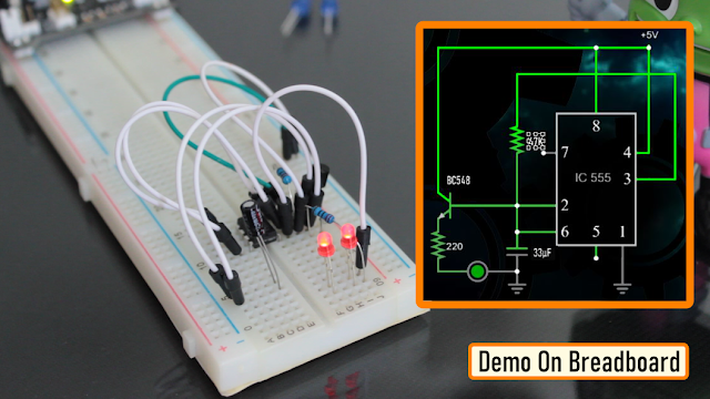 The heart of this circuit is the 555 timer IC.Pin No.1 of the IC is connected to GND.By connecting Pin 2 and 6 of the 555 timer IC, we put the IC in astable mode. In astable mode, the 555 timer IC acts as an oscillator (re-triggering itself) generating square waves [PWM Signals] from the output Pin no. 3.3 other components connect to this junction.1st one is the 33µF capacitor. The positive pin of the capacitor connects to the junction and the negative pin is connected to the GND.2nd one is the 47KΩ resistor. One of its legs connects to the junction and the other leg connects to the Output pin, Pin No.3 of the IC.3rd one is the Base of the BC548 NPN transistor. The collector of the transistor along with Pin 8 and 4 of the IC connects to the +ve terminal. of the battery. The LED along with its current limiting resistor is connected to the Emitter of the transistor.That's it as simple as that.Alright, now I am going to demonstrate how this circuit works with the help of an animation.
How The Circuit Works
- When Pin 2 of the IC detects voltage LESS than 1/3rd of the supply voltage, it turns ON the output on Pin 3.
- And, when Pin 6 detects voltage MORE than 2/3rds of the supply voltage, it turns OFF the output.
This is how the trigger pin (Pin2) and the
threshold pin (Pin6) of the 555 timer IC sense voltages and controls the output at Pin 3.
- The Capacitor attached to the circuit will be in a discharged state immediately after firing up the circuit.
- So, the voltage at Pin 2 will be 0v which is less than 1/3rds of the supply voltage, this will turn ON the output on Pin 3.
- Since Pin 3 is looped back to Pin 2, it will start charging the Capacitor via the 47KΩ resistor.
- At the same time the base current of the transistor also increases causing the LED to slowly "fade-in".
- Once the voltage across the capacitor crosses 2/3rds of the supply voltage, Pin 6 turns OFF the output.
- This causes the capacitor to slowly discharge causing the base current to fall and hence the LED starts "fading-out".
- Once the voltage across the capacitor falls below 1/3rd of the supply voltage, Pin 2 turns ON the output, and the above cycle continues.
You can hook up a multimeter to the circuit to measure the charging and discharging of the capacitor.Breadboard Demo
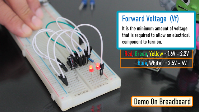 So, here is a quick demo on a breadboard.In the current setup I have a 33µF Capacitor and a Blue LED on the breadboard.Replacing the 33µF Capacitor with a 100µF Capacitor makes the LED fade in-and-out slower as the 100µF capacitor charges and discharges slower than 33µF Capacitor.Also by replacing the "Blue LED" with a "Red LED", we can make the LED to stay "on" longer than the blue one with the same value of capacitor. This is because the "Forward Voltage" (Vf) of the Blue LED is higher than that of the Red LED."Forward voltage" is the minimum amount of voltage that is required to allow an electrical component to turn on.The red, green and yellow LEDs have relatively "low" forward voltage ranging from 1.6-2.2V and hence stays on longer when the capacitor slowly charges or discharged. However, blue and white LEDs starts conducting from 2.5-4V and hence, when the discharging capacitor's voltage hits the threshold the LED turns off faster than the other colors. I have provided a link to how the forward voltage works in the description below.If you connect few LEDs in series, the forward voltage adds up and hence it will require more voltage to turn on the LEDs.
 You need to add a current limiting resistor between the emitter of the transistor and the LED to avoid an internal short-circuiting inside the led.
The Board
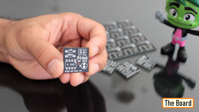 To make it easy for you guys, I have created this tiny little "555 LED Fader Module". After assembling the components, you just need to power this module by providing a voltage between 5v to 15v to fade the LED.
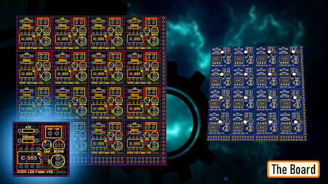 So, this is how my board looks like in 2D and 3D. There are 16 breakout boards in this 100cm x 100cm assembly. You can download the gerber file from the link provided in the description below and order it from PCBWay.
Soldering
 Let me quickly show you guys how to assemble the components to this custom made board.Let's start by soldering the IC Base to the board.Then let's solder the two resistors to the board. Next, lets solder the capacitor followed by the transistor to the board. Then, lets solder a blue LED to the board.Once done, let's insert the 555 timer IC to the IC base.To conclude the setup, I soldered 2 x Female pin headers to the board. You can either solder a pair of female pin-header or male pin-header or solder a pair of wires directly to the board to power this module.
Demo
 Cool, so this is how my module finally looks like.You can install female pin-headers in-place of the LED or Capacitor if you plan to use this as a development/testing board instead of a module.
Thanks
Thanks again for checking my post. I hope it helps you.If you want to support me subscribe to my YouTube Channel: https://www.youtube.com/user/tarantula3Other Links:Support My Work:- BTC: 1Hrr83W2zu2hmDcmYqZMhgPQ71oLj5b7v5
- LTC: LPh69qxUqaHKYuFPJVJsNQjpBHWK7hZ9TZ
- DOGE: DEU2Wz3TK95119HMNZv2kpU7PkWbGNs9K3
- ETH: 0xD64fb51C74E0206cB6702aB922C765c68B97dCD4
- BAT: 0x9D9E77cA360b53cD89cc01dC37A5314C0113FFc3
- LBC: bZ8ANEJFsd2MNFfpoxBhtFNPboh7PmD7M2
- COS: bnb136ns6lfw4zs5hg4n85vdthaad7hq5m4gtkgf23 Memo: 572187879
- BNB: 0xD64fb51C74E0206cB6702aB922C765c68B97dCD4
- MATIC: 0xD64fb51C74E0206cB6702aB922C765c68B97dCD4
Thanks, ca again in my next tutorial. -
When you mix creativity with electronics, it becomes a masterpiece.Producing something original and worthwhile leads to the creation of a number of great new useful household products.In this video, I am going to show you guys how to create this Arduino based touchless concrete clock.3D Design
I always love to generate a 3D model of my product before creating it in real. This not only gives me a better view of what the final product is going to look like, but also helps me in finding the correct measurements of the final product. So, I went ahead and used the free "Windows 3D-builder" to generate this 3D model.The onscreen, black bar is where the TM1637 Digital Clock Module will sit. The gap in the circular concrete frame will house the 5 Blue LEDs that can be turned on or off my moving your hand over the IR Module.These two holes are for the IR Sensor Module. The concrete base bar will house all the remaining electronics components in it.The Template

Based on my 3D-Model I designed this 2D-Template.You can download the template from the link provided in the description below and print it on a A4 paper.Template: DownloadSchematic Diagram

Before going ahead, lets have a look at the schematic diagram of the digital clock. The heart of this circuit is an Arduino Nano.The TM1637 Digital Clock Module connects to D4 and D5 pin of the Arduino.The DS1302 RTC Module connects to the A1, A2 and A3 pin of the Arduino.The two White LEDs displayed on both sides of the digital clock connects to the D11 pin of the Arduino. These two LEDs flash 3 times every hour when the minutes counter is reset to "00".The IR module is connected to the D6 pin of the Arduino and controls the blue cluster of LEDs connected to D12 pin of the Arduino.My initial plan was to have 2 to 3 push button switches connected to D2 and D3 pin of Arduino to set the time of the clock. However in the final version, I did that by adding an extra line of code to my program. I will explain this in full details when we discuss the code.Preparing The Top - Concrete

Using cardboard I created all the concrete molds. Cardboard was my first choice as it is very easy for me to cut and bend it into any shape of my choice.These holes in the mold you see are for the ribbon cables.Sticking this semi-circular piece on the left side of the inner circle will create the gap for the blue LED cluster when we pore the concrete into the mold.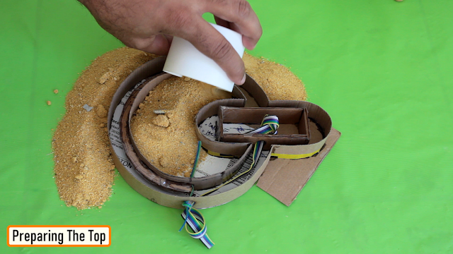
Alright, so this is how it looks like after putting all the pieces of cardboard mold together. Now, lets pour some "Brickies Sand" in-and-around the mold to hold it nice and tight when I pour the liquid concrete. Making the sand a bit wet, will make it firm and will also remove all the unwanted air from the sand.
Cool, now lets go ahead and pour the concrete into the mold. Don't forget to compress the concrete mixture as you pour it. This way the concrete will reach all the necessary places and will also remove the unwanted air bubble from the mixture.
I also added few "Nails" inside the mixture to give it a bit more firmness. This step was absolutely necessary, as my first design completely collapsed because it was not very sturdy.Once the setup dried up I removed all the sand and extracted the piece of art from it.Preparing The Top - Electronics
Alright, now lets start installing the electronic components to the top section of the clock. The 4-Digit LED clock module will sit inside this gap. I will cover it up using a black plastic film which I extracted from a wrapping paper.For the back, I am using a compressed wood board. Based on my initial design I am going to make some holes in the board and install 3 x push button switches to it.The blue LED cluster will be hot-glued in the gap at the back of the circular section.I used a plastic cutout from a milk bottle to cover the Blue LED clusters. The white color of the plastic gave it a gloomy look, which was absolutely super awesome.I hot glues the two white LEDs to the backplate before putting it against the concrete.
 Frankly speaking, it was an absolute challenge for me to hot-glue the backplate on the camera. After struggling for a bit, I did that properly behind the scene.
Preparing The Base - Concrete
Now that we are done with the top section, lets start working on the base of the clock. For the base, I prepared 2 x cardboard boxes with open top one slightly shorter in height than the other. The 2 x straws you see on-screen will create the hole for the IR module. The hole on the side is for the AC power cable.The cardboard block I just added is to create a hole on the top of the base, where the circular-top will sit.
 Then it was just a matter of pouring the sand inside and outside of the cardboard molds followed by pouring the concrete mixture into it.Same as before I added some nails to give the structure some additional firmness.
 Once the concrete dried up, I extracted the concrete base from the sand and carefully sanded the structure to give it a nice and smooth texture.
Preparing The Base - Electronics
Okie-dokie, now lets install the rest of the electronic components inside the base of the clock. I used the same compressed wooden board to create the baseplate and then one by one soldered and hot-glued all the electronics components to it. The IR module I used in this project is one of my self made DIY IR modules. If you want to know more about the module, please checkout my Tutorial No 21 - All About IR Modules and how to make your own DIY IR Module.

Joining The Base To The Top
Now that we have top and the bottom ready, lets go ahead and join them together. I created this cardboard thing to hold the concrete, when I pour the concert in the hole. This cardboard block will also prevent me from poring excessive concrete inside the hole. The flap in the middle is to hold the wires preventing them from getting mixed up with the concrete. After pouring the concrete I left it of drying for almost 2 days.
Code
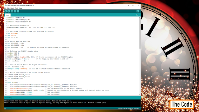 While the concrete was drying up, I complied and uploaded the code to the Arduino.
For this project you need include the "ArduinoRTClibrary" and the "TM1637Display" libraries in your code. You can download them from github from the link provided in the description below.
Lets start the code by creating an instance of the RTC module followed by defining the variables used by the RTC module.
Then, define all the LED pins followed by creating an instance of the TM1637 module and defining all the variables used by the module.
Next, define the pins used by the IR module.
In the setup section, the 1st two lines can be used to attach an interrupt to the code, if you are planning to use the push button switches. However, in my code I am not using the buttons, so I commented them out.
Next, I have set the brightness of the display to the max value = 7 and added the "showNumberDecEx" function to include the colon in the code.
Next, I defined all the pin modes used by the attached components in the code.
The code below can be used to set the time of the clock. Set the correct time, uncomment and then load the code. Once loaded, comment the lines and then load the rest of the code.// Set the current date, and time in the following format: // seconds, minutes, hours, day of the week, day of the month, month, year //myRTC.setDS1302Time(00, 39, 21, 7, 20, 1, 2023);
In the loop section, all we are doing is - reading the hour and minutes from the RTC module and displaying it on the 7-Segment display.myRTC.updateTime(); // This allows for the update of variables for time or accessing the individual elements minutes = myRTC.minutes; // Get the current minutes from the RTC Module hours = myRTC.hours; // Get the current hours from the RTC Modules timeData = hours * 100 + minutes;
This code block is used to toggle the colon on and off.
 // Code block that blinks the colon of the TM1637 module
 if (ctr == 200) {
  if (blinkToggle) {
   display.showNumberDecEx(timeData, 0x40, true);
   blinkToggle = false;
  } else {
   display.showNumberDecEx(timeData, 0, true);
   blinkToggle = true;
  };
  ctr = 0;
 };ctr++;
 delay(5);
This section is used to read the value of the IR sensor and either turn on or turn off the blue LED clusters.// Code block that turns on or off the Blue LED Cluster int Sensordata = digitalRead(IRSensor); // Set the GPIO as Input if (Sensordata != 0) { if (millis() - timestamp>500) { // This is to avoid multiple obstacle detection timestamp = millis(); if (IRtoggler == 0) {digitalWrite(LED_BLUE, HIGH);IRtoggler = 1;} else {digitalWrite(LED_BLUE, LOW); IRtoggler = 0;} }; };
This bit of the code, is to flash the white led when the minute counter resets to 0.// Flash the white LEDs if minutes = 0 if ((int)minutes == 0) { if (blinkCTR==0 || blinkCTR==40 || blinkCTR==100 || blinkCTR==140 || blinkCTR==200 || blinkCTR==240 || blinkCTR==300 || blinkCTR==340) digitalWrite(LED_WHITE, HIGH); if (blinkCTR==20 || blinkCTR==60 || blinkCTR==120 || blinkCTR==160 || blinkCTR==220 || blinkCTR==260 || blinkCTR==320 || blinkCTR==360) digitalWrite(LED_WHITE, LOW); blinkCTR++; }; if ((int)minutes == 1) blinkCTR = 0; // Reset blinkCTR for the next cycle of flashingIf you are planning to use the 2 x push button switches to set the time or to set an alarm, go ahead and uncomment this bit of the code and add your code block to it.
// Pressing this button puts the clock in setup mode
//void Button_1_Pressed(){};
// Pressing this button increments the values on the display
//void Button_2_Pressed(){};
Final Demo

So this is how it finally looks like.Do comment and let me know if there are any scopes of improvement.Thanks
Thanks again for checking my post. I hope it helps you.If you want to support me subscribe to my YouTube Channel: https://www.youtube.com/user/tarantula3Video: https://youtu.be/AQhBpQrfmg8Full Blog Post: https://diy-projects4u.blogspot.com/2023/02/ArduinoClock.htmlOther Links:Template: Download3D Model: DownloadGithub: VisitArduinoRTClibrary: DownloadTM1637Display Library: DownloadSupport My Work:BTC: 1Hrr83W2zu2hmDcmYqZMhgPQ71oLj5b7v5LTC: LPh69qxUqaHKYuFPJVJsNQjpBHWK7hZ9TZDOGE: DEU2Wz3TK95119HMNZv2kpU7PkWbGNs9K3ETH: 0xD64fb51C74E0206cB6702aB922C765c68B97dCD4BAT: 0x9D9E77cA360b53cD89cc01dC37A5314C0113FFc3LBC: bZ8ANEJFsd2MNFfpoxBhtFNPboh7PmD7M2COS: bnb136ns6lfw4zs5hg4n85vdthaad7hq5m4gtkgf23 Memo: 572187879BNB: 0xD64fb51C74E0206cB6702aB922C765c68B97dCD4MATIC: 0xD64fb51C74E0206cB6702aB922C765c68B97dCD4Thanks, ca again in my next tutorial. -
Created a small "PCB Christmas Forest" which is going to light up my study table this Christmas.In this video, I am going to show you guys how to design these PCBs and assemble them to create a small PCB Christmas Forest.
Designing The PCBs
Sorting Out Images

To start the designing process, I need transparent PNG images of the Christmas Tree, Star, Snowflake, Candy Cane etc.So I went online, and did an "image search" and downloaded few black-and-white images of all the items that I need to design these PCBs.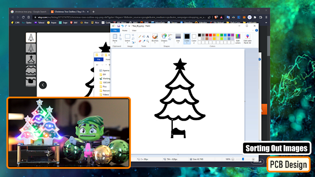
Using the good old "MS Paint" I edited all these PNG files.I removed the rounded base and made the base flat so that it easily sits on the base plate. Then I removed a small portion from the bottom to expose a bit of copper. Pouring a blob of solder on this plate will hold the PCB nice and tight from the front side on the baseplate.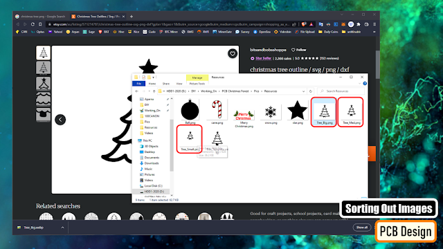
In my design I have 3 different sizes of the trees. If you look closely, they are all extracted from the same tree by removing the bottom layer each time and hence generating a new size of the tree.Generating DXF File
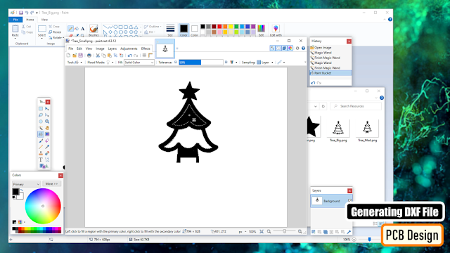
For the customized shapes of the PCBs, we need to generate "DXF files" to set the "Board Outlines". I am using the "paint.net" application to fill in the white spaces of the tress as I only need the borders and nothing else from the original images. Then, I uploaded the images to "https://convertio.co/" and generated the DXF files. This website allows 10 free conversions in a day unless you have a paid account with them.
Creating the Trees

Now, lets add a "New PCB" to our project and remove the default board outlines.Then import the DXF files via File > Import > DXF menu. Make sure you have the "BoardOutLine" selected under layers when you import the dxf file.Now lets import the image that will go on the Top Silk Layer. Put the image over the board outline and move it to the "TopSilkLayer". Then lets go ahead and decorate our tree. Once all set, lets hide the Top Silk Layer so that we can work on the rest of items.Using the Rectangle tool from the "PCB Tools Plate" I added a rectangle to the bottom of the PCB. I exposed the copper, so that I can use this to hold the tree on the baseplate by poring a blob of solder on it.Next I randomly added few LEDs here and there at the bottom side of the board. Then I added few exposed copper rectangles at the back side of the board and connected them the LEDs. Remember this is just an example, the attached gerber is totally different from what you see onscreen.So, this is how the tree looks like in 3D.Creating the Baseplate
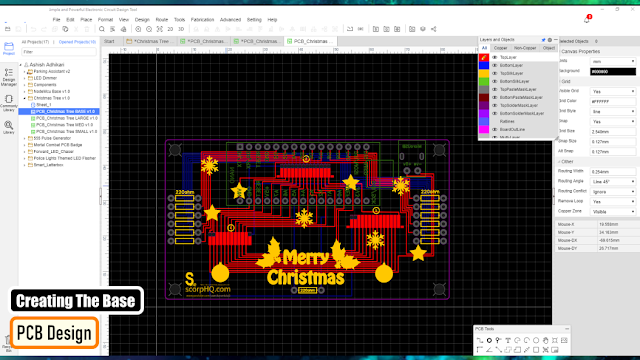
Now to create the baseplate, we again need to add a "New PCB" to our project and remove the default board outlines.Then go to Tools > Set Board Outline.. and select the "Round Rectangular" from the "Type" selection. Specify the height, width and the radius of the edge and hit the "Apply" button.Then go-ahead and add the rest of the components one by one either to the "TopLayer" or the "BottomLayer" of the board and connect them using wires. I grabbed the back and the front exposed rectangles from the tree and added them to the baseplate. This way the spacings will remain intact when we solder the trees on the baseplate. That's it easy as that. Now just go ahead and download your gerber file and send it for fabrication.So, this is how my baseplate looks like. Bit complex, but it has the exact same logic that I just showed you guys.Ordering Process
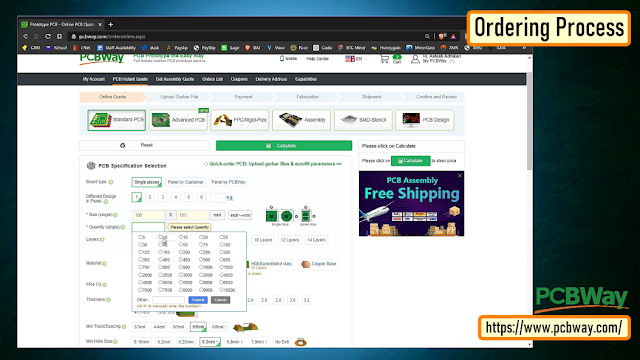
Once I had my design ready, I just had to upload the gerber file to the PCBWay's website and select the type, color and any other customization that I want and then just send it for fabrication.For my project, I choose the black, red and the green colors.
The Code

The code I wrote is very simple. I have just turned on and off the LEDs after a 500ms delay. The top white LEDs turn on and off in the opposite order to the rest of the LEDs.This code is just an example, you can write all sorts of funky stuff and load it to your Arduino board.Testing on Breadboard

I tested my code on a breadboard before soldering the LEDs to the board. I wanted to see if the Arduino Nano can handle that many LEDs at once and I also wanted to check if combining different color LEDs on a same pin of Arduino will have any adverse effect.The result was pretty promising:- I was able hook up 3 LEDs without any issues to all the Digital (except D13) and Analogue pins of the Arduino.- I was "not" able to combine yellow and orange LEDs with any other color on the same pin of Arduino.Soldering
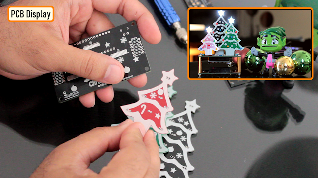
So, this is what came in the mailbag. Have a look at the quality, its absolutely mind-blowing.Based on my design, the black one will stay at the back, the green one on right and the red one on the left hand side of the baseplate.Please make sure when you solder the trees, solder the small (red) one first, then the green one and finally the big black one at the back. This way, you will be able to solder them very easily, without going over or under the trees.Now, lets start soldering.
Lets start by soldering the LEDs on the trees. Since the front side of the plate has all the decorations on it, I placed all the component markings at the back side of the plate.I then one by one soldered all the LEDs on the front side of the plates.Please be careful while adding the colors, as mentioned earlier you cannot hook up yellow and orange with any other color on the same pin of an Arduino. Please follow my final coloring patter.
Now lets get the baseplate sorted. Lets start by soldering all the resistances to the board.Then, lets solder 2 x female pin headers to the board. These pin headers will house the Arduino Microcontroller in it.After that, lets solder the 2 pin micro-USB port to the board.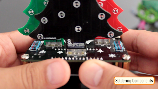
Next, its time to solder the trees to the board. With lots of flux and very little solder this is what I ended up creating.
Since a lot of the LEDs were getting hidden behind the trees, I ended up removing a lot from the final version.Just follow the onscreen color pattern and you will have a small Christmas forest sitting on your table in less than 30 minutes.Merry Christmas and Happy New Year...Thanks
Thanks again for checking my post. I hope it helps you.If you want to support me subscribe to my YouTube Channel: https://www.youtube.com/user/tarantula3Video: Video LinkFull Blog Post: Blog PostCode: DownloadImage Resources : DownloadGerber Base : DownloadGerber Small Tree : DownloadGerber Medium Tree : DownloadGerber Big Tree : DownloadGitHub : VisitSupport My Work:
- BTC: 15cNh9hup8jidCVPwa1DTcxeoh2FPijVrX
- LTC: LbquH9Ku78vHtcm3LZnWXpD1JQWdKzeV4v
- DOGE: DEB2QBAihnBRhGsaB8P7kz559TDiucQhX6
- ETH: 0x5d8c9ba0e54d8354d4af81871db26daa190d2194
- BAT: 0x939aa4e13ecb4b46663c8017986abc0d204cde60
- LBC: bZ8ANEJFsd2MNFfpoxBhtFNPboh7PmD7M2
- COS: bnb136ns6lfw4zs5hg4n85vdthaad7hq5m4gtkgf23 Memo: 572187879
- BNB: 0x5d8c9ba0e54d8354d4af81871db26daa190d2194
Thanks, ca again in my next tutorial. -
Intro
In my hand is a 4-Digit 7-Segment display module.The heart of this module is an inexpensive Serial LED Driver from Titan Micro Electronics called the TM1637.In this tutorial, I am going to show you guys how to control the TM1637 4-Digit 7-Segment displays using an Arduino. If you want to displays sensor data, temperature and humidity, or want to design a clock, timer or counter, you will need this 4-Digit Seven-Segment Display.Topics Covered

In this tutorial we are going to talk about:The Basics of a 7-Segment DisplayHardware Overview and Pinout of The TM1637 ModuleTM1637 Library InstallationInterfacing TM1637 Module with an ArduinoLoading The Basic Arduino Code (that comes with the TM1637 library)Then we will have a look at some of these quick examples:Example 1: Displaying String and a NumberExample 2: Displaying Scrolling and Blinking TextExample 3: Creating a 4 Digit CounterExample 4: Displaying Temperature & Humidity using DHT11/DHT22Example 5: Creating an Arduino Based Digital ClockAnd finally we will have a look at some common errors.7-Segment Display Basics
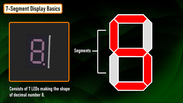
A 7-Segment Displays consists of 7 LEDs making the shape of decimal number 8. These LEDs are called segments, because when they light up, each segments contributes in the formation of part of a decimal or hex digit.These individual segments are labeled from ‘a’ to ‘g’ representing each individual LED. By setting a particular segment HIGH or LOW, a desired character pattern can be generated.Hardware Overview and Pinout of TM1637 Module
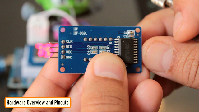
The module comes with 4 right angle male pin headers. I find it a bit annoying to have the pin headers on the top side of the board. However, you can always unsolder and put them at the bottom of the board.Now lets have a look at the GPIO pins:CLK - is the clock input pin. You can connect it to any digital pin of an Arduino.DIO - is the Data I/O pin. This can also connect to any digital pin of an Arduino.VCC - Connects to 3.3V to 5V power supply.GND - is the ground pin.CLK and DIO pins can be connected to any digital pin of an Arduino. This gives us an opportunity to hook up a lot of these modules to an Arduino, as long as each instance has a pin pair of its own. When writing the code, we just need to specify the pin pair and then just go ahead and use them in your project.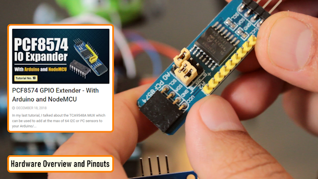
If you run out of pins on your Arduino board you can use a GPIO Pin Extenders like the PCF8574. Please check out my tutorial on the Extender module, the link is in the description below.PCF8574 GPIO Extender: https://diyfactory007.blogspot.com/2018/12/pcf8574-gpio-extender-with-arduino-and.htmlThe module has 4 x 0.36 segment 7-Segment Displays and a ‘colon’ at the center for creating clock or time-based projects.A bare four digit 7-Segment Displays usually requires 12 connection pins but the TM1637 LED Driver removes the need of the extra wiring for the 7-Segments and the entire setup can be controlled just by using 2 wires (DIO and CLK) and two more for power reducing the total wires to 4.These modules communicate with the processor using "I2C-like protocol". The implementation is pure software emulation and doesn't make use of any special hardware (other than GPIO pins).The module operates between 3.3v to 5v with a current consumption of 80ma and allows adjusting the brightness of the LEDs at the software level. They are available in few different colors.TM1637 Library Installation
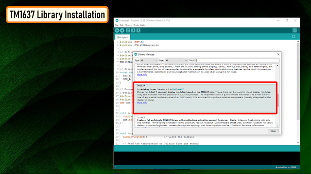
There are many libraries available for the TM1637 module. For this tutorial, we are going to use the "TM1637Display Library" written by "Avishay Orpaz". You can download the library using the library manager or from Github, the link is in the description below.To install the library using "Library Manager", navigate to Sketch > Include Library > Manage Libraries…Search for "TM1637" and look for the one by "Avishay Orpaz". Hit the "Install" button to install the library on your device.- TM1637Display Library: Download
Interfacing TM1637 Module with an Arduino
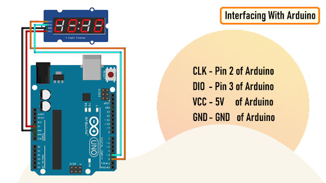
Hooking up the TM1637 module to an Arduino is very easy.You just need to connect four wires: 2 for power and other 2 for controlling the display.You can connect the VCC of the module to either 3.3v or 5v pin of the Arduino.So, connect:CLK - Pin 2 of ArduinoDIO - Pin 3 of ArduinoVCC - 5V of ArduinoGND - GND of ArduinoAs previously advised, you can use any pin combination for the CLK and DIO on the Arduino board. Just make sure you change the pin numbers in the code to reflect the change of wiring.So far, based on my experience I have only found one disadvantage.This module is unable to display floating points or dots between numbers. However, you can use the "HT16K33 module" for displaying floating points.Loading The TM1637Test Example
Before going ahead, lets have a look at the example that comes with the TM1637 Library.Navigate to File > Examples > TM1637 and load the "TM1637Test" example.The sketch starts by including the "TM1637Display.h" library.Then it defines the CLK and the DIO pins that will be used to connect the TM1637 display.In this example Pin-2 of Arduino is used for CLK and Pin-3 for DIO.#include <TM1637Display.h>#define CLK 2#define DIO 3Next, you need to create a new instance of the "TM1637Display" class by passing the CLK and the DIO Pin values to it.TM1637Display display(CLK, DIO);
Then, the code shows us 2 ways of displaying data on the individual segments by creating arrays of texts.a. 1st by passing "hexadecimal numbers" to the individual displaysuint8_t data[] = {0xff, 0xff, 0xff, 0xff};
Passing "0xff" to all the 4 displays will turn them all ON, and passing "0x00" will turn them all OFF.Using the "display.encodeDigit()" function you can display digits between 1 and 15.data[0]= display.encodeDigit(15); // This will display F___ on the display [0b01110001 = F]display.setSegments(data);This will display F___ on the display.b. 2nd by individually specifying the segments that you want to turn on.The below creates an array that sets the individual segments values and displays "dOnE" on the display.uint8_t done[] = {SEG_B | SEG_C | SEG_D | SEG_E | SEG_G, // dSEG_A | SEG_B | SEG_C | SEG_D | SEG_E | SEG_F, // OSEG_C | SEG_E | SEG_G, // nSEG_A | SEG_D | SEG_E | SEG_F | SEG_G // E};Now, to display these arrays, you need to pass them to the "display.setSegments()" function.display.setSegments(data); // Will turn off all LEDsdisplay.setSegments(done); // Will display "dOnE"The setSegments function accepts 3 argumentssetSegments(data[], length, position);
Data = The data to displayLength = number of digits to be updated (0–4). Ex. for "dOnE", it will be 4, for the "°C" it will be 2.Position = determines the position from which you want to print (0-leftmost, 3-rightmost).Remember, the LEDs once turned on stays on until they are turned off. So, you always have to clear the previous value before displaying the new one. This can be done by passing 4 lots of 0xffto the "display.setSegments()" function or by using "display.clear()" function.uint8_t data[] = {0xff, 0xff, 0xff, 0xff};display.setSegments(data);The brightness of the display can be adjusted using the "setBrightness()" function. The function accepts values between 0 (lowest) to 7 (highest).display.setBrightness(3); // Sets the brightness level to 3
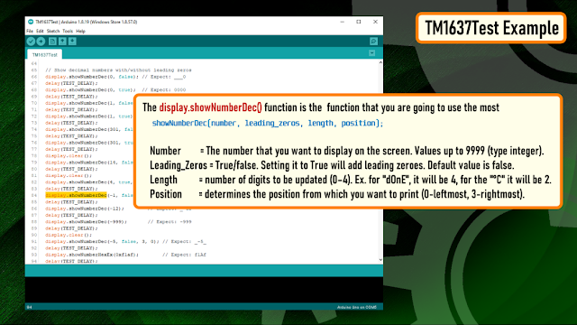
The "display.showNumberDec()" function is the function that you are going to use the most to display numbers on the module. The first argument is a number that you want to display on the screen. The rest of the arguments are all optional.Syntax:showNumberDec(number, leading_zeros, length, position);
Number = The number that you want to display on the screen. Values up to 9999 (type integer).Leading_Zeros = True/false. Setting it to True will add leading zeroes. Default value is false.Length = number of digits to be updated (0–4). Ex. for "dOnE", it will be 4, for the "°C" it will be 2.Position = determines the position from which you want to print (0-leftmost, 3-rightmost).Example:display.showNumberDec(1,false) // Displays ___1display.showNumberDec(1,false,1,0) // Displays 1___display.showNumberDec(1,false,1,2) // Displays __1_display.showNumberDec(10,false,2,0) // Displays 10__Template

For the rest of the examples, I am going to use this template to write the code.I will only show you guys the bit which is different in each code.Example 1: Displaying Strings and Numbers
 In this example you can see letter "TEST" and a randomly generated number is alternating and getting displayed on the screen.To display the letter TEST, I am first clearing the screen and then lighting up the individual segments to display the characters.To display a number, I am first generating a random number between 0 and 9999 and then displaying it using the "display.showNumberDec()" function.
- Example1: Download
Example 2: Displaying Scrolling and Blinking Text

Now, to display a scrolling text, I am incrementing the position of the text by 1 and then displaying it from the new position. You need to pad the display with any character or it will end up showing random characters on the display.Blinking a text is super easy. All you have to do is display the text, add a delay, clear the screen and then again add a delay before displaying the text again.- Example2: Download
Example 3: Creating a 4 Digit Counter
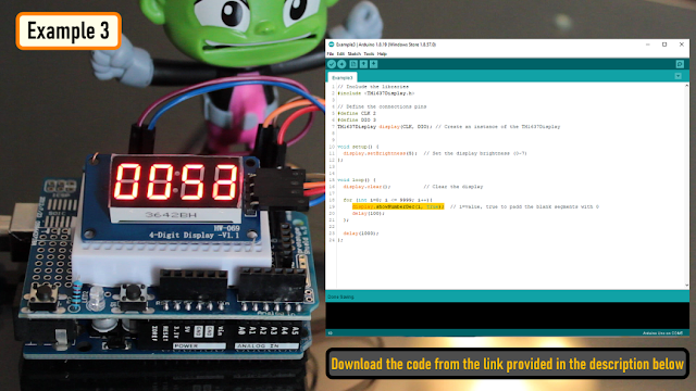
To display a counter, I am looping from 0 to 9999 and displaying the incremented value every time on the 7-Segments.You can also add a push button switch to start and stop the counter.- Example3: Download
Example 4: Displaying Temperature & Humidity using DHT11/DHT22
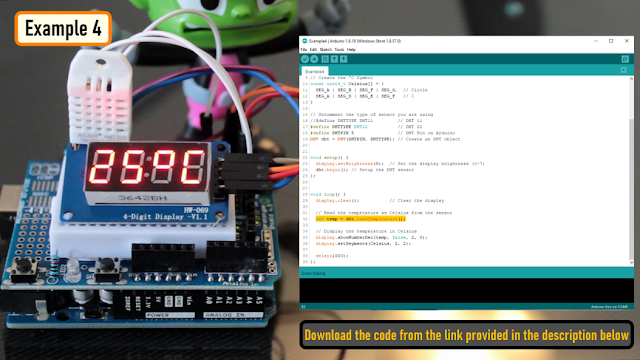
Connect the OUT pin of the DHT11/DHT22 sensor to Pin-5 of the Arduino.Then in the code include the "DHT.h" library and define the DHTPIN and the DHTTYPE.Next, create a DHT object and in the setup section initialize the DHT sensor using the "dht.begin()" function.Next in the loop section read the sensor data using the "dht.readTemperature()" function and display it on the 7-Segments.- Example4: Download
Example 5: Creating an Arduino Based Digital Clock
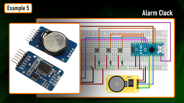
You can also create an alarm clock using either the DS3231 or DS1302 RTC Module and display the data using this TM1637 module.I will cover that in full details in my next video.Common Errors

Now lets have a look at some off the common errors:Display showing parts of the previous data.You always have to clear the previous value before displaying the new one.You can either use:display.clear();
oruint8_t data[] = {0xff, 0xff, 0xff, 0xff};display.setSegments(data);Display data going out of the display or showing partiallyCheck the positioning of the display data.setSegments(data[], length, position);
These are few of the issues that I came across while playing around with these displays.Do comment and let me know if you have any more to add to the list.Thanks
Thanks again for checking my post. I hope it helps you.If you want to support me subscribe to my YouTube Channel: https://www.youtube.com/user/tarantula3Links:Code:Support My Work:- BTC: 15cNh9hup8jidCVPwa1DTcxeoh2FPijVrX
- LTC: LbquH9Ku78vHtcm3LZnWXpD1JQWdKzeV4v
- DOGE: DEB2QBAihnBRhGsaB8P7kz559TDiucQhX6
- ETH: 0x5d8c9ba0e54d8354d4af81871db26daa190d2194
- BAT: 0x939aa4e13ecb4b46663c8017986abc0d204cde60
- LBC: bZ8ANEJFsd2MNFfpoxBhtFNPboh7PmD7M2
- COS: bnb136ns6lfw4zs5hg4n85vdthaad7hq5m4gtkgf23 Memo: 572187879
- BNB: 0x5d8c9ba0e54d8354d4af81871db26daa190d2194
Thanks, ca again in my next tutorial. -
Intro
What do you generally do when your remote controls starts playing up?- Do you generally use a multimeter and check the voltage and current produced by the battery?
- Or do you point the remote control to a digital camera and try to visualize the infrared light?
In this video, I am going to show you guys how to create a simple InfraRed(IR) Receiver Circuit using TSOP4838 and will also show you how to read the code send by the remote controls. You can also use this circuit as an IR remote tester.Setup Without Arduino
 Lets first have a look at the setup without an Arduino.The main component of this circuit is the Infrared Remote (IR) Receiver TSOP4838.The TSOP4838 is tuned to 38kHz, which is typically the frequency range of the TV remote controls.
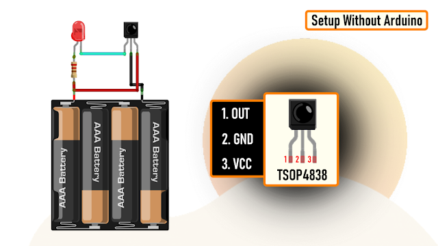
From left to right Pin-1 is the OUTput pin, Pin-2 is GND and Pin-3 is VCC. Just remember, the pin assignments can be different depending upon the TSOP variant. So, please be very careful while hooking it up to your circuit.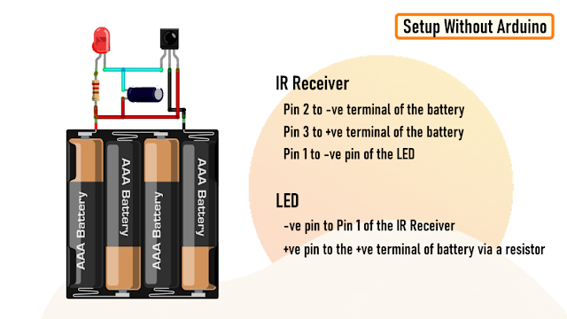
Now, lets have a look at the setup.Connect Pin-2 of IR Receiver to the -ve and Pin-3 to the +ve terminal of the battery.Then connect the -ve pin of the LED to Pin-1 of the IR Receiver and the +ve pin to the +ve terminal of the battery by placing a current limiting resistance in-between.To reduce the flickering rate of the LED, you can add a capacitor anything between 10mfd to 100mfd between Pin-3 and VCC of the circuit.That's it, as easy as that.Demo Without Arduino
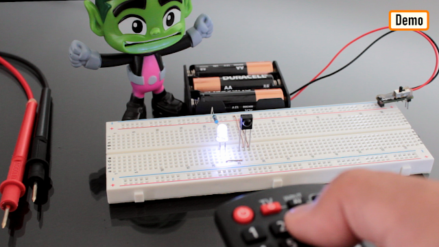
Now, lets do a quick test.As you can see, when I press any button on the the remote control the LED starts flickering.TSOP4838 demodulates the signals received from the remote control and gives the output in the form of active low to the LED.Adding a capacitor will lower the flickering rate of the LED.The supply voltage has to be strictly between 5V-6V.Setup Using Arduino

Now, lets set this up using a MicroController and try to read the demodulated signals.Connect the +ve pin of the IR Receiver to 5V, -ve to GND and the OUT pin to Pin-2 of the Arduino.You can also add the optional LED to this setup to get a visual effect when the Receiver decodes the signal.
The Code

Now, go ahead and launch Arduino IDE and go to "Tools" > "Manage Libraries".Download and Install the latest release of the "IRremote" library from the library manager.Then, go to "Examples" and open the "SimpleReceiver" example. Go ahead and load the code without making any modification to the Arduino Board.Demo Using Arduino

For this demo, I am using a Panasonic and a Sony remote control. The decoded data will be shown using the Arduino IDE's Serial Monitor.As you can see when I press a button on the remote control, the LED lights up and the decoded data is displayed on the serial monitor.
The serial monitor displays a lot of information, but the one of my interest is the "Source" and the "Command" send by the remote control.Uses
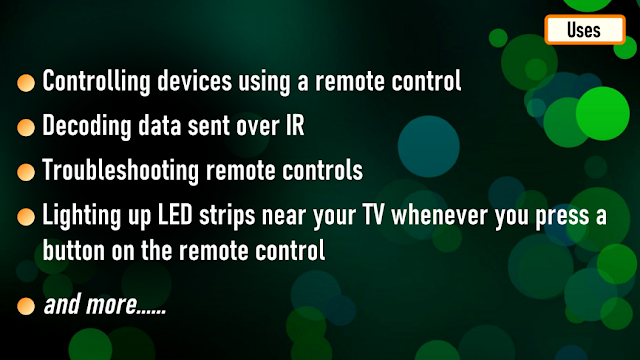
Some common uses of this project includes:Controlling devices using a remote controlDecoding data sent over IRTroubleshooting remote controlsLighting up LED strips near your TV whenever you press a button on the remote controlThanks
Thanks again for checking my post. I hope it helps you.If you want to support me subscribe to my YouTube Channel: https://www.youtube.com/user/tarantula3Video: Video LinkFull Blog Post: Blog PostDatasheet: DownloadSupport My Work:BTC: 15cNh9hup8jidCVPwa1DTcxeoh2FPijVrXLTC: LbquH9Ku78vHtcm3LZnWXpD1JQWdKzeV4vDOGE: DEB2QBAihnBRhGsaB8P7kz559TDiucQhX6ETH: 0x5d8c9ba0e54d8354d4af81871db26daa190d2194BAT: 0x939aa4e13ecb4b46663c8017986abc0d204cde60LBC: bZ8ANEJFsd2MNFfpoxBhtFNPboh7PmD7M2COS: bnb136ns6lfw4zs5hg4n85vdthaad7hq5m4gtkgf23 Memo: 572187879BNB: 0x5d8c9ba0e54d8354d4af81871db26daa190d2194Thanks, ca again in my next tutorial. -
Intro
Walkie-talkie using Arduino, humm.. sounds interesting isn't it?Alright, lets spend some time today and design and understand this fairly simple circuit, and lets find out how our expectations are challenged by the reality.Story
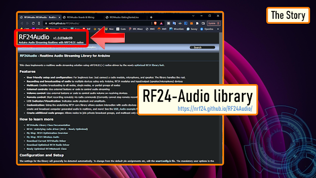 While compiling data for my tutorial on "nRF24L01 Module" (All About nRF24L01 Modules) I found this easy to use RF24-Audio library.
 This library has all the basic functionalities that you need to make a DIY walkie-talkie. The sketch is very simple, and I had all the components required to assemble this on a breadboard.
 To motivate me even further, I found tons of video tutorials of people making this "super cheap gadget" with "crystal clear voice" transmitted over "1km to 2km of range". Humm, sounds a bit doggy but I still wanted to give it a shot.This audio library works on top of the RF24 library.
Logic
 Lets start by looking at the schematic of this circuit and lets also find out the components required to assemble this circuit.Before going into much details lets understand the basic requirements of this circuit.To transmit and receive data from one unit to the other we need some sort of transceiver module and a MCU to process the data.We need some sort of device/module to capture our voice, and a device/module to convert the sound waves received in the form of electrical signal and relay it as an audible sound wave.To start the transmission we need a push button and a LED indicator which lights up when the transmission begins. Similarly, at the receiving end we need a LED indicator that lights up when the unit starts receiving data.
Schematic
 Alright, now lets replace our logic with the electronic components.The heart of this circuit is an Arduino Nano.The voice is transmitted from one unit to the other using a nRF24L01 Transceiver Modules.Using a Microphone Module connected to the A0 pin of the Arduino, I am going to capture my voice.And, using a 8ohm 0.5W speaker, connected to the D9 and D10 pin of the Arduino I am going to output the voice received by this circuit.To initiate the transfer I am using a push button switch connected to the A1 pin of the Arduino.The Red LED connected to the pushbutton lights up, when we press the button to transmit data.The Green LED connected to the D6 pin of the Arduino lights up when the unit starts receiving data.We also need to add a large decoupling capacitor anything from 470uF upwards on the 3.3V line to filter out voltage spikes and to provide enough power to the IC to keep the voltage stable.You may also need to provide additional power to the nRF24 module using a 3.3V voltage regulator.
 To transmit and receive data, we need exact copies of this module at both transmitting and receiving ends.
The Code
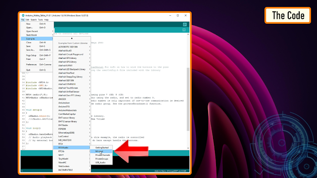 Now lets have a look at the code.Unless you want to do something super funky, just go ahead and upload the "Minimal" code provided with the RF24Audio library to both the Arduino's present at the transmitting and receiving ends.The code works perfectly fine with the circuit diagram we discussed in the previous section.
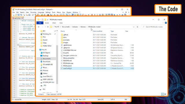 If you want to change any of the pin combinations, then you need to edit the "userConfig.h" file which you can find inside the Arduino libraries folder.That's all you have to do to get this all up and running.
Demo
 Alright, now the interesting bit. Lets go ahead and test this super cheap Arduino based walkie-talkie.As you can hear, the sound quality is a total disaster.I tried a few things like altering the sampling rate, altering the transfer speeds, adding a better microphone and an amplifier circuit, but nothing helped to improve the audio quality. This circuit is a total disaster.I feel like I wasted my weekend making this project, and I am glad that I did not end up designing a PCB for this setup.
 Frankly speaking, with this setup you can get about 20 meters or less with concrete walls in between. So, if you have a little faith in me, DONT WASTE YOUR TIME MAKING THIS STUPID PROJECT AT HOME.
Thanks
Thanks again for checking my post. I hope it helps you.If you want to support me subscribe to my YouTube Channel: https://www.youtube.com/user/tarantula3Video: Video LinkFull Blog Post: Blog PostLibrary: DownloadHow to wire the buttons to the Arduino: Blog PostAll About nRF24L01 Modules: Video LinkCode: DownloaduserConfig.h: DownloadSupport My WorkBTC: 1M1PdxVxSTPLoMK91XnvEPksVuAa4J4dDpLTC: MQFkVkWimYngMwp5SMuSbMP4ADStjysstmDOGE: DDe7Fws24zf7acZevoT8uERnmisiHwR5stETH: 0x939aa4e13ecb4b46663c8017986abc0d204cde60BAT: 0x939aa4e13ecb4b46663c8017986abc0d204cde60LBC: bZ8ANEJFsd2MNFfpoxBhtFNPboh7PmD7M2Thanks, ca again in my next tutorial. -
Intro
My 5-year old son asked me to create a Police Car like flashing light that he can put on top of his nerf-gun, while playing around with his mates. No worries mate, sounds like a plan to me. Bang, weekend sorted.In this tutorial I am going to create a Police Light themed LED Flashing circuit using the 555 timer IC. This circuit alternatively flashes between the Red and the Blue LED's while blinking each of them individually similar to the police strobe lights. To add some spice to this project you can also add a police siren to this circuit. However, I just wanted to keep it simple.Watch this video (https://youtu.be/4vDtWafMF0M) for detailed step by step instructions on how to build this circuit and for a complete instruction on how the circuit works.Disclaimer: This tutorial and the linked video are for educational purposes only.Components Required

For this project we need:- 6 x RED LEDs
- 6 x Blue LEDs
- 2 x 555 Timer ICs
- 2 x 1K Resistors
- 1 x 680K Resistor
- 1 x 100K Resistor
- 1 x 10uf Capacitor and
- 1 x 100nF Ceramic Capacitor (104)
Depending upon the input voltage and the way you connect the LEDs (series or parallel) you will have to use different values of resistors in series with your LED’s. Please checkout http://ledcalc.com/ to calculate the resistor values based on your LED arrangements.How The Circuit Works
Now, let's try to understand how this circuit works.This circuit has 2 parts.- Part 1: Where the Blue and Red LEDs alternate and flash at a regular interval
- Part 2: Where a cluster of similar color LEDs flash like a strobe light
In my previous tutorial "Adjustable Single/Dual LED Flasher Using 555 Timer IC", I showed you guys how to configure 555 timer IC to operate in an astable mode. In astable mode, the 555 timer IC acts as an oscillator (re-triggering itself) generating square waves [PWM Signals] from the output pin no. 3. Later I also showed you guys how to connect 2 LED’s in opposite polarity at the output pin Pin-3 so that they toggle ON and OFF at regular intervals of time.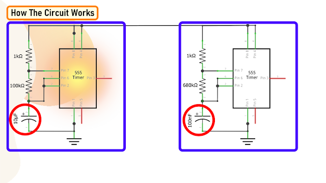
In this tutorial, I am using two copies of the previously shown "astable circuit" configured at different frequencies.The first 555 timer IC, uses a higher value capacitor and hence it takes more time to toggle the output.The second 555 timer IC uses a lower value capacitor and hence it toggles the output very fast.So, pretty much that's exactly what we want. The 1st 555 timer IC will help us in toggling between the LED clusters and the 2nd 555 timer IC will produce the strobe light effect.
Now, lets connect the LED clusters to this circuit. The first LED cluster of the Red LED’s turns ON when the anode receives a positive voltage and the cathode is grounded. This happens when the output of first 555 timer IC is ON and at the same time the output of second 555 timer IC is OFF.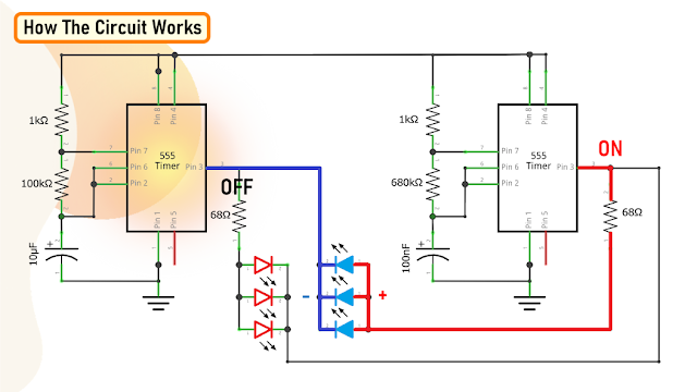
Similarly, the second cluster of the Blue LED’s turn ON only when the output of the first 555 timer IC is OFF and the output of the second 555 timer IC is ON.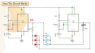
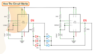
Now, when the first 555 timer IC is ON it turns on the first cluster of Red LED’s and they blink at the speed at which the second 555 timer IC oscillates the output.Similarly when the first 555 timer IC turns OFF, the second cluster of Blue LED’s turns ON and blinks at the speed at which the second 555 timer IC oscillates the output.This cycle continues as long as there is power in the circuit creating a cool LED flashing effect similar to the flashing lights used on police cars.You can change the frequency of "toggling" between the successive LED groups by changing the higher value capacitor. Increasing its value will increase the time between the successive toggling between the two LED clusters and vice versa.Similarly, changing the value of the lower value capacitor will change the "blinking rate" of the LED clusters.Demo On Breadboard
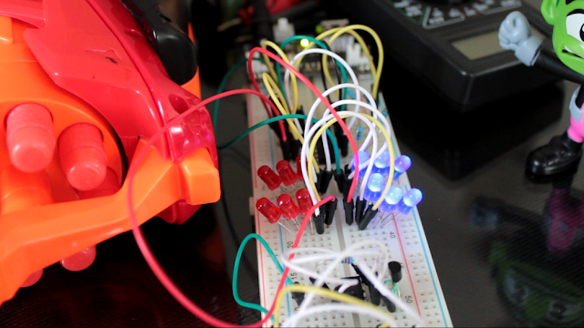
The Board

So, this is how my board looks like in 2D and 3D.I have placed both ICs and all other electronics components to the middle of the board.To give the assembly a bit nicer look, I have placed the LED clusters on both sides of the board.Alright, now lets start soldering the components to the board.Soldering

Since I care a lot about my ICs and microcontrollers I never solder them directly to the board.In case of ICs, I always try to use IC bases or if a base is not available I use female pin headers.
After soldering the IC bases, I am soldering all the resistances to the board.
Next, I am soldering the capacitors to the board followed by all the LEDs to the board.I am also soldering a female micro USB port to power this circuit board.Always check the polarity before soldering the socket to your board.
To conclude the setup, I am installing the ICs to the IC bases.Final Demo

So, this is how my final setup looks like.Do comment and let me know if there are any scopes of improvement.Thanks
Thanks again for checking my post. I hope it helps you.If you want to support me subscribe to my YouTube Channel: https://www.youtube.com/user/tarantula3Full Blog Post: Blog PostVideo: Video LinkRelated Videos1. Adjustable Single/Dual LED Flasher: Video Link2. 555 Pulse Generator Module, How it Works: Video LinkGerber File: DownloadSchema: DownloadResistor Value Calculator: Open WebsiteSupport My WorkBTC: 1M1PdxVxSTPLoMK91XnvEPksVuAa4J4dDpLTC: MQFkVkWimYngMwp5SMuSbMP4ADStjysstmDOGE: DDe7Fws24zf7acZevoT8uERnmisiHwR5stETH: 0x939aa4e13ecb4b46663c8017986abc0d204cde60BAT: 0x939aa4e13ecb4b46663c8017986abc0d204cde60LBC: bZ8ANEJFsd2MNFfpoxBhtFNPboh7PmD7M2Thanks, ca again in my next tutorial. -
The 555 timer IC is an integrated circuit that is used in a variety of timer circuits, pulse generators and oscillator applications. The heart of the tutorial is the 555 timer IC that is wired as an astable multivibrator.In this tutorial, I'll first blink "an LED" using the positive pulse generated by a "DIY 555 Pulse Generator Module" (video: https://youtu.be/bMAnipPOjFo), followed by "two LEDs" alternating and flashing at a regular interval. The output frequency of pulses can be adjusted using a potentiometer. The circuit can be operated from any voltage between 5 to 15 volt DC.
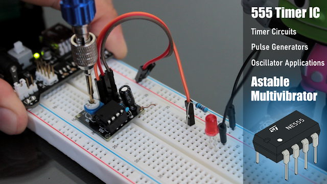 Watch this video for detailed step by step instructions on how to build this circuit and for a complete instruction on how the circuit works.
Items Required

For this tutorial we need:2 x LEDs1 x 555 Timer IC1 x 10µF Capacitor1 x 220Ω Resistor1 x 1kΩ Resistor1 x 10kΩ Resistor and/or1 x 10kΩ PotentiometerCircuit Diagram

The circuit is very simple.By connecting Pin 2 and 6 of the 555 timer IC, we put the IC in astable mode. In astable mode, the 555 timer IC acts as an oscillator (re-triggering itself) generating square waves [PWM Signals] from the output pin no. 3.By changing the values of R1, R2, and C1 we can change the frequency of the output pulses generated at pin number 3.Alright, let me explain this with the help of an animation.How The Circuit Works

* When Pin 2 of the IC detects voltage LESS than 1/3rd of the supply voltage, it turns ON the output.* And, when Pin 6 detects voltage MORE than 2/3rds of the supply voltage, it turns OFF the output.* When the output is OFF, the Discharge Pin (Pin7) gets internally Grounded.This is how the trigger pin (Pin2) and the threshold pin (Pin6) of the 555 timer IC sense voltages and controls the output at Pin 3.
* Capacitor C1 will be in a discharged state immediately when we firing up the circuit.* So, the voltage at Pin 2 will be 0v which is less than 1/3rds of the supply voltage, this will turn ON the output on Pin 3.* At the same time Pin 7 will internally disconnect from the GND and the Capacitor C1 will start changing via resistors R1 and R2.* Once the voltage across capacitor C1 crosses 2/3rds of the supply voltage, Pin 6 turns OFF the output.* At the same time Pin 7 will internally reconnect to the GND causing the capacitor C1 to discharge via resistor R1.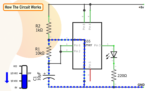
* Once the voltage across the capacitor C1 falls below 1/3rd of the supply voltage, Pin 2 turns ON the output, and the above cycle keeps repeating itself.You can hook up a multimeter to the circuit to measure the charging and discharging of the capacitor.Since resistance R1 is involved in both charging and discharging of the Capacitor, increasing or decreasing its value will increase or decrease the duration of the OFF cycle and will decrease or increase the flashing rate of the LED, as the capacitor will take more time to charge and discharge.By replacing the capacitor with a higher or lower value, you can also get a longer or shorter flashing rate.By replacing the resistor R1 with a potentiometer the blinking rate of the LED can be dynamically adjusted.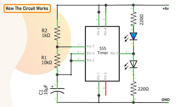
Now, for the Dual LED flashing effect we need to connect a second LED with opposite polarity to the Pin 3 of the IC. That's it, as easy as that.Calculations

Now, lets calculate the output frequency and the duty cycle of the output waveform.In my setup I have resistance R1 = 1kΩ, R2 = 10kΩ and capacitor C = 10uFThere are many online calculators to calculate this online. I will provide a link to one of the astable calculators in the description below: https://ohmslawcalculator.com/555-astable-calculatorLets first calculate the value of t1 or the 'capacitor charge “ON” time which is 0.693(R1 + R2 ) * C1. Putting the values together we get 76.23 milliseconds.Now, for capacitor discharge “OFF” time or t2 we need to multiply 0.693 to R2 and C1, which then gives us a value of 69.3 milliseconds.Next, the total periodic time T is equal to t1 + t2 which comes out to be 145.53 milliseconds.The output frequency, ƒ is therefore comes out to be to 6.871Hz.Which gives a duty cycle value of 52.38%If you want to have more control over the charging and discharging use a higher value for R2 (100K) and lower value for R1 (1K). That way you will have 99% control over the charging and discharging resistance in the circuit.The maximum output current of this IC is 200mA therefore to drive a higher current load of up to 1A we have to use a transistor like the BD135.The Board

To make it easy for you guys, I have created this tiny little "555 Pulse Generator Module". After assembling the components, you just need to power this module by providing a voltage between 5v to 15v to get an oscillating output at the "Pulse" pin.So, this is how my board looks like in 2D and 3D. There are 16 breakout boards in this 100cm x 100cm assembly. You can download the gerber file from the link provided in the description below and order it from PCBWay.Soldering
 Before moving forward, let me quickly show you guys how to assemble the components to this custom made board.Let's start by soldering the IC Base to the board. Then let's solder the potentiometer to the board. After that lets solder the 1kΩ (R1) resistor to the board followed by the 10µF capacitor (C1) to the board. Once done, let's insert the 555 timer IC to the IC base.To conclude I have soldered 3 x Male pin headers to the board.
Applications and Uses

- This circuit can be used to control the speed of DC motors and Stepper motors
- It can be used to control windscreen wiper motors to generate a to-and-fro motion
- It can be used as square wave signal generator
- It can be used as an adjustable pulse generator for MCUs
- In Strobe lights and SoS signaling circuits
- Telecommunications for encoding purposes
- In turning indicator circuits for all types of vehicles and bicycles
- To generate adjustable pulse (timing pulses) to control other circuits. As, in combination with the 4017 & 4026 ICs

-
I have used this IC in few of my other projects and tutorials like the:
- DIY - Boba Fett Helmet With LED Chaser Circuit : https://youtu.be/vtO_GD0SS2s
- LED Chaser Circuits Using IC4017 and Arduino : https://youtu.be/F6V1AjESWbU
- DIY - LAN CABLE TESTER : https://youtu.be/PSK5Aa-byHA
- 555 Pulse Generator Module : https://youtu.be/bMAnipPOjFo
Thanks
Thanks again for checking my post. I hope it helps you.If you want to support me subscribe to my YouTube Channel: https://www.youtube.com/user/tarantula3Full Blog Post: Blog PostVideo: Video LinkRelated Videos1. DIY - Boba Fett Helmet With LED Chaser Circuit : Video Link2. LED Chaser Circuits Using IC4017 and Arduino : Video Link3. DIY - LAN CABLE TESTER : Video Link4. 555 Pulse Generator Module, How it Works : Video LinkGerber File: DownloadCalculator: DownloadSchema: DownloadSupport My WorkBTC: 1M1PdxVxSTPLoMK91XnvEPksVuAa4J4dDpLTC: MQFkVkWimYngMwp5SMuSbMP4ADStjysstmDOGE: DDe7Fws24zf7acZevoT8uERnmisiHwR5stETH: 0x939aa4e13ecb4b46663c8017986abc0d204cde60BAT: 0x939aa4e13ecb4b46663c8017986abc0d204cde60LBC: bZ8ANEJFsd2MNFfpoxBhtFNPboh7PmD7M2Thanks, ca again in my next tutorial. -
In my last tutorial I created a NodeMCU based Duino Coin Miner. It is an awesome little miner that sits on my desk and mines few cents a day.However, adding these miners to my home network choked my WiFi router. Home Appliances and Smart Devices connected to the router constantly started dropping off. To my understanding, most of the wireless routers and access points can support upto 250 devices connected at once. So, what's happening here?To clarify my doubts I called my ISP. The answer they gave was absolutely shocking. "ONLY 30 devices can successfully connect and exchange data via their router at any given time". Bloody hell!!So, to overcome this limitation I added another router to the network to scale up the load.But, I was not happy with this solution. So, I did a bit of research and found this "NRF24L01 RF Transceiver Module" which I can use to create a mesh of wirelessly connected microcontrollers.In this tutorial, I am going to show you guys how to use this transceiver module to add wireless communication between two or more Arduino boards. I will be using this module for many of my upcoming home automation projects. Bang Problem solved..
What is a NRF24L01 RF Transceiver Module?
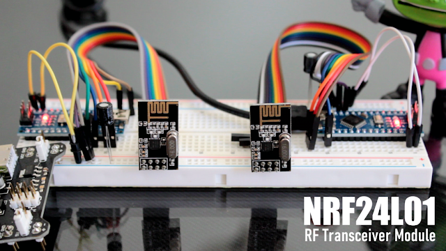
So far, I have always used WiFi for wireless communication between microcontrollers. While this is easy enough to do, it is not exactly suitable for battery operated nodes. WiFi modules consume a lot of current when transmitting data plus they also have a slight delay when initiating the transmission as the module has to first connect to the WiFi network.After getting crippled by the abilities of my wireless router, I found this cheap, very popular and widely used "RF Transceiver Module" which you can hook up to any microcontroller (MCU). This module is called a RF transceiver because a single module can work both as a transmitter and a receiver.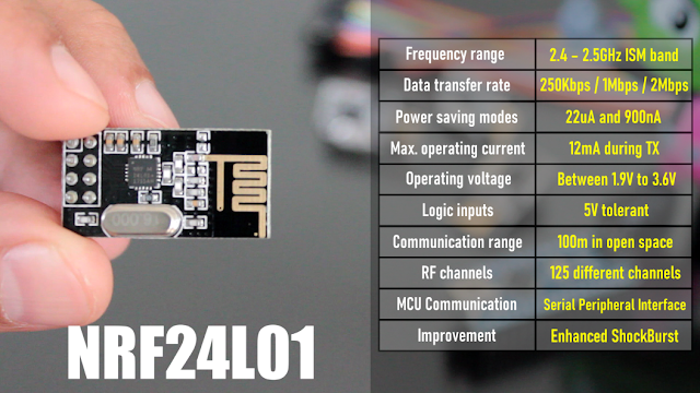
- The module operates at a frequency of 2.4GHz, which is one of the ISM band which means it is open to use in most of the countries around the World.
- Data transfer rate is between 250kbps to 2Mbps baud.
- Power consumption? This module is designed for ultra low power wireless applications. It has 2 power saving modes operating at 22uA Standby-I mode and 900nA in power down mode - which makes these modules suitable for battery operated nodes. The high air data rate combined with two power saving modes makes the nRF24L01 module very suitable for ultra low power designs. The power consumption of this module is just around 12 milliamps during transmission (TX) which is even lower than a single led.
- Operating voltage is between 1.9V to 3.6V. All other pins on this board are 5V tolerant making it easy to connect to an Arduino without using a logic level converter. It has an integrated (on chip) voltage regulator.
- The Range of this module as per its datasheet is 100m but it works up to 50 to 60 meters in real world conditions.
- The module has 125 independent RF channels giving the possibility to have a network of "125 independently working modems" in one place. Each channel can have up to "6 addresses or 6 data pipes" or in other words, each unit can communicate with up to 6 other units at the same time (1:6 star networks).
- The module is configured and operated through a Serial Peripheral Interface (SPI).
- It uses Enhanced ShockBurst™ for automatic packet assembly and timing, automatic acknowledgement and retransmission of packets. Enhanced ShockBurst™ enables the implementation of ultra low power, high performance communication with low cost host microcontrollers. The features enable significant improvements of power efficiency for bi-directional and uni-directional systems, without adding complexity on the host controller side.

The module used in this video has an in-built PCB antenna making it compact. However, you can also buy a variant that supports an external antenna allowing much higher range of about 1000M in line of sight.nRF24L01 Pinout
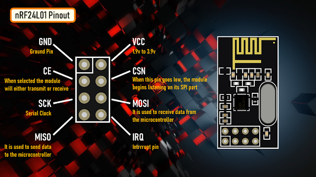
Now, lets have a look at the pinouts and specifications of the NRF24L01 module:- GND: is the Ground Pin. It is placed inside a square for easy identification.
- VCC: supplies power to the module. Voltage can range from 1.9v to 3.9v. So, you can connect it directly to the 3.3V pin of our Arduino. Remember connecting it to a 5V pin will likely destroy your nRF24L01+ module!
- CE: (Chip Enable) is an active-HIGH pin. When selected the module will either transmit or receive, depending upon which mode it is currently in.
- CSN: (Chip Select Not) is an active-LOW pin and is normally kept HIGH. When this pin goes low, the module begins listening on its SPI port for data and processes it accordingly.
- SCK: (Serial Clock) it accepts clock pulses provided by the SPI bus Master.
- MOSI: (Master Out Slave In) It is SPI input to the module. It is used to receive data from the microcontroller.
- MISO: (Master In Slave Out) It is SPI output from the module. It is used to send data to the microcontroller.
- IRQ: It is the interrupt pin that alerts the master when new data is available to process.
Setup and Schematic
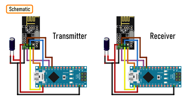
In order to get this working, we need two such NRF24L01 Modules and two Arduino Boards. For this tutorial I am going to use 2 Arduino Nanos.Just remember, we cannot use a breadboard with these modules because the pin spacing on these modules are not enough to place it in the middle and if you place it anywhere else, then you will end up shorting the pins. This means that you will either have to solder the wires directly to the modules or use some sort of jumper cables.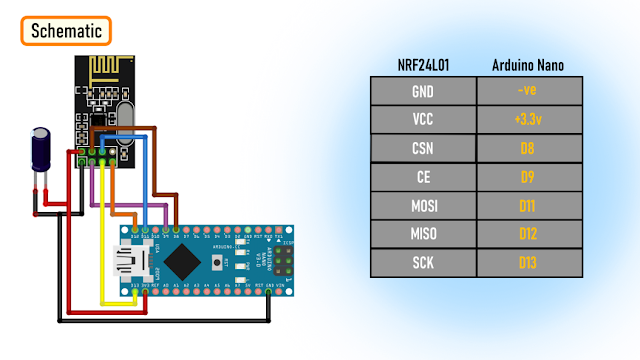
The connection is exactly the same on both the transmitter and receiver end.Connect the GND pin to -ve and VCC pin to 3.3v pin of Arduino. The signals generated by these modules are very sensitive to power supply noises. So, adding a decoupling capacitor (anything from 10uF to 100uF) across the power supply line is always a very good idea.Then connect the CSN pin to D8, CE to D9, MOSI to D11, MISO to D12, and SCK to D13 pin of the Arduino.Since the nRF24L01+ module requires a lot of data transfer, it will give the best performance when connected to the hardware SPI pins on the microcontroller. Note that each Arduino board has different SPI pins that must be connected accordingly. Have a look at the table onscreen for quick understanding.Library Used

For this tutorial I am going to use the "TMRh20/RF24" OSI Layer-2 driver for nRF24L01 on Arduino & Raspberry Pi/Linux Devices. You can download the library from the link provided in the description below: https://github.com/tmrh20/RF24/.Code 1 - Sending Text
In my first example, I am going to send a character array from one module to the other. Using a split screen I am going to demonstrate this example. On my left is the Transmitter Code and on my right is the Receiver Code.Lets start by including the "SPI library" followed by the "RF modules library" downloaded from github in the code.Then we are creating a RF24 object by passing the CSN and CE as the two arguments to the radio() function.Next, we are creating an array of the addresses that the modules will use to communicate amongst themselves. The address can literally be anything, however, it has to be the "same" on both the transmitter and the receiver modules. This is how the RF modules know who they have to communicate with.In the setup section we first initialize the radio object.Then, using the radio.openWritingPipe() function we set the address of the transmitter which we will use to send data to the receiver module. On the receiving end we use the radio.openReadingPipe() function with the same address to read the data from the data pipe.Next we set the power amplifier level. Since the modules in this demo are sitting next to each other, I am using the "Minimum Level".Next, in the transmitter code we need to tell the module to stop listening using the radio.stopListening() function. This sets the module as a transmitter. On the receiver module we need to start listening using the radio.startListening() function. This sets the module as a receiver. After that, in the loop() section of the transmitter, we send an array of characters using the radio.write() function and on the receiver end we read the array using the radio.read() function and display it on the serial monitor every second.Code 1: Download
Code 2 - Lighting Up LEDs
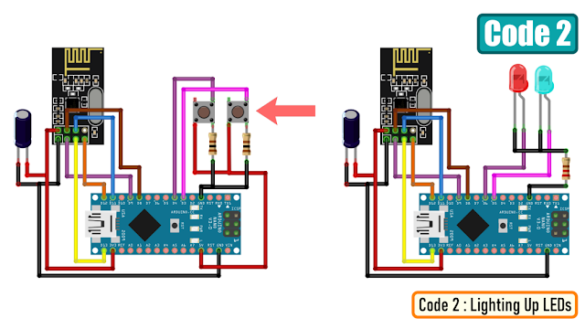
In the second example, I am going to light up two LEDs on the receiver-end based on whichever button is pressed on the transmitter-end.
To achieve this I have added 2 LEDs on the receiver end and 2 Push Button switches on the transmitter end.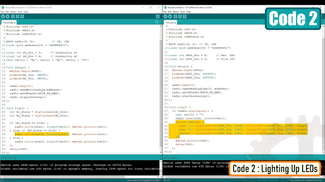
When Button B1 is pressed the transmitter sends "B1" using the radio.write() function and when Button B2 is pressed the transmitter sends "B2" using the radio.write() function to the receiver module.The "switch statement" in the receiver code then lights up the corresponding LED based on whichever button was pressed on the transmitter end.Code 3 - Same Node Acting as TX and RX [Bidirectional Communication)

In my 3rd example I will show you guys how a single node can act as both transmitter and receiver. Just remember you "cannot" send and receive data at the same time. Using the "stopListening()" and "startListening()" functions we will toggle between sending and receiving of data on the data pipes.What's different here from the previous code is that we are creating two pipes or addresses for the bi-directional communication.const byte addresses[][10] = {"ADDRESS01", "ADDRESS02"};In the setup section we need to define both pipes in a way that the sending address of the 1st module is the receiving address of the 2nd module and vice versa the receiving address of the 1st module needs to be the sending address of the 2nd module.Now in the loop section of the 1st Arduino, we use the radio.stopListening() function to turn the node into a transmitter and send the data using the radio.write() function.On the receiver end we use the radio.startListening() function to read the incoming data. While there is incoming data (radio.available()) we read it using the radio.read() function. Then we add a bit of delay to the code.After that, we set the 1st Arduino to receiving mode using the radio.startListening() function and the 2nd Arduino to transmitting mode using the radio.stopListening() function. The data is then displayed on screen using the Serial Monitor.Code 3 : Download
Code 4 - Multiple Nodes [Mesh - Multiceiver Network]

The nRF24L01+ has a feature called Multiceiver. It is an abbreviation for Multiple Transmitter Single Receiver. In my 4th example, I am going to show you guys how to connect multiple transmitters to a single receiver.In a Multiceiver network each RF channel is logically divided into 6 parallel data channels or the data pipes. Each data pipe has its own unique data pipe address. Only one data pipe can receive a packet at a time.So basically, the primary receiver in the middle is collecting data from 6 different transmitting nodes simultaneously. The primary receiver can stop listening any time and start acting like a transmitter.This way you can create a mesh of network where each node can act as a repeater. There is a different library "RF24Mesh" you need to use to create this mesh network. Since I don't have that many modules handy at this moment, I am unable to show you guys the working bit of it. However, I will create a 2nd tutorial dedicated just to the mesh network, so stay tuned.Using Sleep Mode

There is a way to conserve battery by sending the module to sleep mode. Please read through the "pingpair_sleepy" example for more details, I have provided the link in the description below.Factor Effecting The Transmission

- These modules work very well when the transmitter and receiver are close to each other. If the distance is too big you may lose the communication.
- The signals generated by these modules are very sensitive to power supply noises. Depending upon the amount of noise, the communication rate may vary.
- Setting the maximum output power can also improve the communication range.
- If there’s an obstacle in the line of sight you may see multiple dropouts.
- Reducing the data rate can significantly improve the performance. A speed of 250kbps is more than enough for most of our projects.
- Using an external antenna can also significantly improve the transmission rate.
- Another potential source of noise for RF circuits is WiFi. Especially when someone's network is set on the same channel. Since WiFi mostly uses the lower frequency channels, it is recommended to use the highest 25 channels for your nRF24L01+ modules.
Thanks
Thanks again for checking my post. I hope it helps you.If you want to support me subscribe to my YouTube Channel: https://www.youtube.com/user/tarantula3Blog Posts: Visit WebsiteVideo references: Visit WebsiteDataSheet: DownloadSchemaSchema - Sending Text: DownloadSchema - Lighting Up LEDs: DownloadCodeCode 1 - Sending Text: DownloadCode 2 - Lighting Up LEDs: DownloadCode 3 - Bidirectional Communication: DownloadLibraries UsedTMRh20/RF24 : Visit WebsiteTMRh20/RF24 : DownloadRF24Mesh : Visit Websitepingpair_sleepy : Visit WebsiteSupport My WorkBTC: 1M1PdxVxSTPLoMK91XnvEPksVuAa4J4dDpLTC: MQFkVkWimYngMwp5SMuSbMP4ADStjysstmDOGE: DDe7Fws24zf7acZevoT8uERnmisiHwR5stETH: 0x939aa4e13ecb4b46663c8017986abc0d204cde60BAT: 0x939aa4e13ecb4b46663c8017986abc0d204cde60LBC: bZ8ANEJFsd2MNFfpoxBhtFNPboh7PmD7M2Thanks, ca again in my next tutorial. -
Crypto Mining using microcontrollers, wait what!!! Are you serious? How?Believe it or not, the rig you see onscreen actually mines a crypto currency called DUINO-Coin (ᕲ) or DUCO.The total cost of this rig is only $35.Now, if you believe me! then, grab yourself a cup of coffee, sit back and watch this video and start your journey into cryptocurrency with DUINO-Coin!
What is DUINO-Coin?
 DUINO-Coin (ᕲ) was founded in 2019 and is a for-fun project. This project was developed by a team of young developers that focuses on energy efficient mining. It's mostly, but not only, dedicated to people who are just starting out in the crypto world and it doesn't require any expensive hardware.DUCO is a transparent, open-source, centralized, eco-friendly coin that focuses on mining with low-powered devices like Arduino. DUCO tries to achieve a reward system using "Kolka" a name derived from Coca Cola making the low-powered devices like Arduino earn almost the same or even "more" than a powerful device like CPUs or GPUs. It also prevents people from building huge mining farms. It causes each additional miner to earn a bit less from the previous one.DUCO is "centralized" and has an "infinite supply" and hence you can mine this coin forever.You can Mine DUCO using:Android smartphoneComputer's CPUArduino (or compatible AVR)Raspberry Pi, Orange Pi or Banana PiESP8266/ESP32 (or compatible boards)Internet browser on PC or smart-TVsArduinos using ESP8266 as a hostArduinos using Raspberry Pi as a hostCentralization: Making Arduino and other low powered devices not only profitable, but just possible would be impossible to maintain if the coin was decentralized. Hence, DuCo is a centralized coin with it's own chain. It is however possible to wrap (convert) DUCOs to wDUCO, bscDUCO, celoDUCO or maticDUCO to store them in decentralized form on another coin's chain.To start your journey, have a look at the getting started with Duino-Coin webpage. Then, create a wallet to store your coins. Next, download the miner binaries for the device you are going to mine the coin.If you are super tech savvy, then have a look at the coins whitepapers. The link is in the description below.In my setup, I am mining DUCO using NodeMCU.
Schema
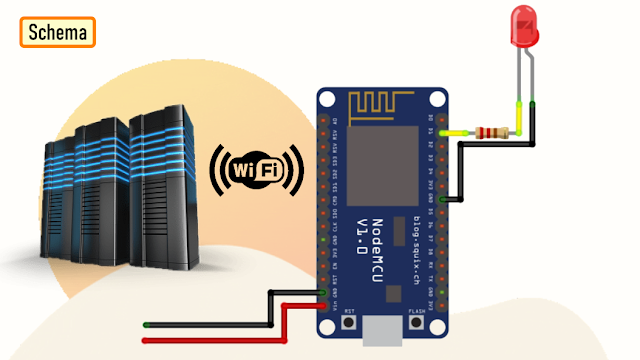 The setup is very simple. In my setup I have added an extra LED to give my board a bit of Si-Fi look.Mining with ESP boards allows you to mine headlessly - you don't need to have them connected to a computer as they have their own Wi-Fi capabilities to connect to the server.
The Board

Now, lets have a look at my board. You can hookup, 5 x NodeMCUs to this board. Each NodeMCU has its own flashing LED. The board can be powered using just 5v using a USB cable.So, this is how the NodeMCU DUCO Miner blade looks like in 3D.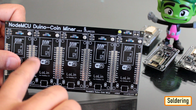
Soldering
 Lets start by soldering all the small components to the board.I first soldered all the LEDs and the resistances to the board.Since I care a lot about my Sensors and Microcontrollers, I am not going to solder them directly to the board. Instead I am soldering 'female pin headers' to the board which will house the NodeMCUs in them.
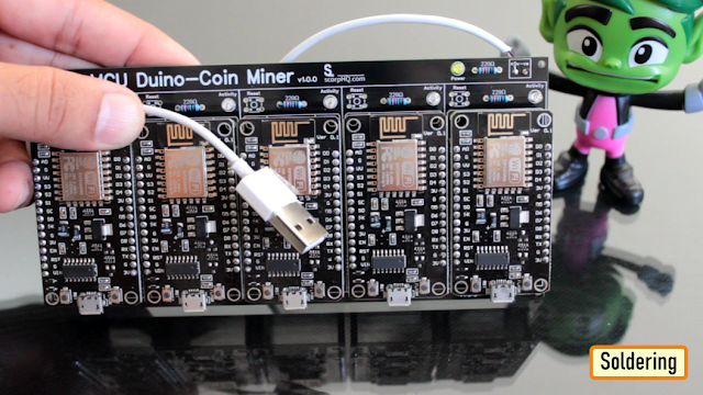 Finally, I soldered a USB cable to power the blade. I extracted this cable from a broken iPhone's charger.
Code
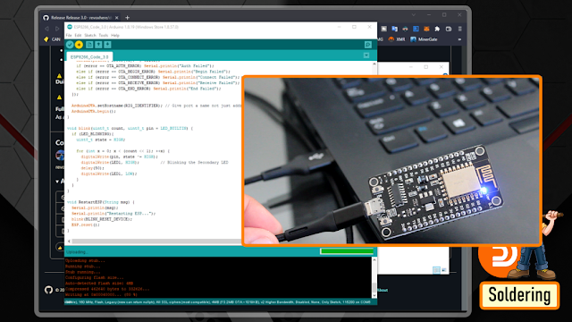
I downloaded the code from the DUINO-coins website. The current version is 3.0. I downloaded the windows version and then added my code block to make the blue LED flash on my blade.In the code, you just need to edit few line in the top section to add your Wi-Fi details and the name of the NodeMCU.If you're using an ESP8266 board, you can set the clock speed (Tools > CPU frequency) to 160 MHz to achieve better hash-rates.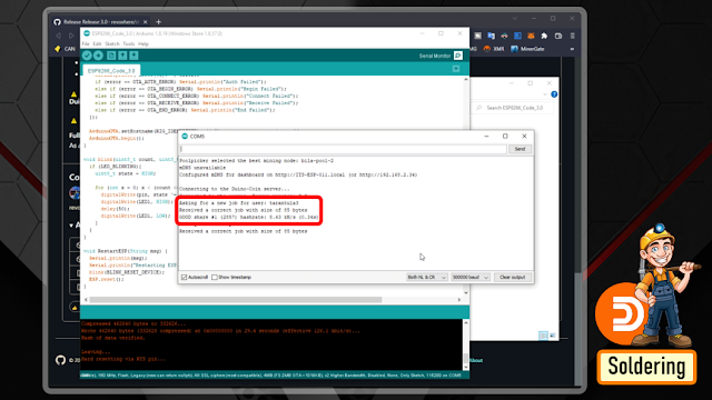 Then, just go ahead and upload the code one by one to all your NodeMCU's. Before adding the NodeMCU to your rig, it is a good idea to check it using the Arduino Serial Monitor (Tools > Serial Monitor), set the baud rate to 500000 baud and see how's the ESP is doing. If everything is correct, you should see messages saying that a share was accepted.If it all works fine, your ESP will mine as long as it has power and internet connection.
Demo

So, this is how my final setup looks like.To be very frank, the setup actually looks like having a small Christmas tree on your table, ha ha.Hash-Rate

Mining DUCO at this stage is not very profitable. However, I just wanted to share the hash-rate table with you guys.Remember, Kolka will play an essential role, as you keep on adding devices to your rig.So, the hash-rate you will get may not be same as what you see on-screen.Claiming Via Faucets

You can also claim DUCO via web-faucets.I have scene many faucets coming in and completely disappearing, so the links provided in the video may not be valid when you try to access them.The first one in list is the "faucet.duinocoin.com". You can claim 1 DUCO from this website by solving a captcha to start your journey. Remember you can only claim once from this website.The next one is the "furim.xyz". Again, you just need to solve a captcha to earn some DUCO.The 3rd one in list is "duco-faucet.pcgeek.pl" same as the other two, you can claim some DUCO every 15 minutes by solving a captcha on this website.Exchanging DUCO
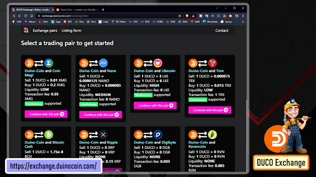
After mining some DUINO-Coins, you may want to exchange them to some other currency.To exchange your coins, simply visit the website and select the currency you want to exchange. At the moment of writing this tutorial, DUCO Exchange supports XMG, BCH, TRX, BYND and LKE coins.After deciding which coin you want exchanged, simply fill in the exchange form and wait for the exchange to happen (it may take up to 72 hours). You'll shortly receive an e-mail confirming the process and describing any further steps if needed.Other exchanges:Other exchanges supporting DUINO-Coin are Node-S, PancakeSwap, SunSwap, and SushiSwap.Thanks
Thanks again for checking my post. I hope it helps you.If you want to support me subscribe to my YouTube Channel: https://www.youtube.com/user/tarantula3Blog Posts: Visit WebsiteVideo references: Visit WebsiteCodeRelease 3.0 Original: DownloadRelease 3.0 Modified: DownloadResource PagesGetting started: Visit WebsiteCreate Wallet: Visit WebsiteApp list: Visit WebsiteExchange: Visit WebsiteWhite Paper: Visit WebsiteDashboardsDashboard-1: Visit WebsiteDashboard-2: Visit WebsiteDashboard-3: Visit WebsiteFacets ListFaucet-1: Visit WebsiteFaucet-2: Visit WebsiteFaucet-3: Visit WebsiteDiscussionDiscord: Visit WebsiteReddit : Visit WebsiteSupport My Work:BTC: 1M1PdxVxSTPLoMK91XnvEPksVuAa4J4dDpLTC: MQFkVkWimYngMwp5SMuSbMP4ADStjysstmDOGE: DDe7Fws24zf7acZevoT8uERnmisiHwR5stETH: 0x939aa4e13ecb4b46663c8017986abc0d204cde60BAT: 0x939aa4e13ecb4b46663c8017986abc0d204cde60LBC: bZ8ANEJFsd2MNFfpoxBhtFNPboh7PmD7M2Thanks, ca again in my next tutorial. -
In my last tutorial I created a Weather Station using Arduino and NodeMCU using DHT11 or DHT22 temperature and humidity sensor and displayed it using an OLED Display. In this tutorial, I am going create a Peg-Box using the same board but with a little bit of twist. In this setup, I am going to send the Temperature and Humidity readings to my Raspberry Pi based home server and store it in a MySQL database. The data can then be viewed using PHP and Google Charts, on a Mobile Phone or a PC connected to the home network.
Circuit Diagram
The setup is very simple. The temperature and humidity sensor sends the collected data to the NodeMCU on pin D3. NodeMCU then sends the data over WiFi to the Raspberry Pi, which is then saved in the MySQL database.The Yellow LED, which is the status indicator flashes every second and is connected to D6 pin of the NodeMCU. The Blue LED connected to pin D5, lights up when NodeMCU sends the temperature and humidity readings to the database.If you are planning to install this box somewhere inside the house, then you can also add an OLED display and display the readings on it.The Board
So, this is how my board looks like in 2d and 3d.There are 3 breakout boards in this 100cm x 100cm assembly. Each board can be used with either Arduino or NodeMCU and DHT11 or DHT22 sensor or sensor module.Temperature and humidity readings can be collected using either a DHT11 or DHT22 Module or by using one of these sensors with a 10K resistor.The bottom section of the board is for the OLED display. The attached gerber is bit different from what you see on screen. I made some modifications in the final version and moved the sensors a bit far from the microcontrollers.Component Assembly
Lets start by soldering the female pin-headers to the board. The pin-headers will house the NodeMCU in it.Next, lets soldered few more pin-headers for the LEDs, DHT11 sensor and the OLED display.Before installing the circuit in the peg-box, lets hook up the OLED Display and make sure everything works as expected. Boom, nailed it.The Code
The code starts by including all the libraries and by defining all the constants and variables that will be used throughout the program.Then there are two functions SendIamAlive() and SendTemperatureAndHumidity() which sends heartbeat and the data read from the temperature sensor to the database server.The ReadDHTSensor() function reads the data from the DHT11 or DHT22 sensor.In the setup section we first setup the WiFi and then send a SendIamAlive() message to the server advising that it is back up and running. Then in the loop section the microcontroller send a heartbeat every minute using the SendIamAlive() function and if the time elapses it sends the humidity and temperature data using the SendTemperatureAndHumidity() function.The White LED flashes every seconds and the Blue LED turns on when the device sends the temperature and humidity data to the database server.MySQL
So,the data sent by the NodeMCU over WiFi is saved in the MySQL database hosted on a RaspberryPi 4.Here you can see, the microcontroller sends the data every 30 minutes (you can change the frequency) which is then saved in the MySQL database. The data saved on the Pi's MySQL database can then be used to generate various different types of graphs either by using google charts or any other 3rd party application. It totally depends on you how you want to present it.3D Design
Now, lets look at the design of the peg-box. Using freely available pallet planks, I designed the body of the box.The pallet planks I am using are 160cm x 9cm x 2cm (length, width and thickness). So, the rest of the measurements will be based on that.The top bit of the peg-box will house the microcontroller and the sensors in it. Putting it on the top prevents the electronics from adverse climatic conditions.The back bit will stick to wall and hence we don't need to cover it up.You can either put the pegs straight in the front bin or throw it to the top bit, from where it will slide down to the front bin.The sliding design with an opening in the front will prevent rainwater from accumulating inside the bin. This mechanism will keep the bin dry throughout the year.Woodworking
Using 2 hammers I am dismantling the pallet. My aim is to reuse all the nails used in building this pallet so that, I can use them in building my project. After that, I sanded the pallet planks to give them a nice and smooth texture.Then using a chop-saw or a hand-saw I extracted all the pieces of wood required for building this project.
As mentioned earlier, my pallet plank are 9cm wide and hence, all the onscreen measurements are based on that.Final Assembly
Using wood-glue I am joining all pallet planks used in making the box.I got a bit too excited and accidentally deleted one of my recordings. So, I am using 3D animation to show you guys how I joined the two sides of the box.I used a plywood board to created the base of the bin.I glued few cylindrical wooden sticks on the roof of the box. To be very frank these sticks changed the entire outlook of the peg-box.Coloring
Since my aim is to install the peg-box outside the house, I have to make sure that I apply multiple coats of paint on the box to avoid the pallet wood from rotting. I applied 3 coats of paint on the entire setup and insulated all the holes that I found using wood putty.So, this is how it looks like. The electronics bit will stay hidden under the roof of the box. Ha ha, Don't worry, I will obviously insulate them and make them weather-proof before installing them on the wall.Installation
Now the next thing you need to do is to find a spot where you want to install this unit.I am installing this near my clothesline, however you may want to install it in your pantry or behind a door or something like that. It totally depends on how much space you have and where you want to install it.I am using metal frame hangers to hang this on the wall.Place the unit against the wall, and using a pencil mark the points where you want to drilling the holes.Now, using a hammer drill, drill the holes in the wall.Then, put the wall plugs in the wall and then use a screw driver to install the screws.Alright so, that's it. This unit is now all set to hold all my pegs in it.Demo
So, this how my final setup looks like. Do comment and let me know if there are any scopes of improvement.Thanks
Thanks again for checking my post. I hope it helps you.If you want to support me subscribe to my YouTube Channel: https://www.youtube.com/user/tarantula3Blog Posts:1. Peg BoxVideo references:1. Peg BoxResources:Code:Libraries:Support My Work:BTC: 1M1PdxVxSTPLoMK91XnvEPksVuAa4J4dDpLTC: MQFkVkWimYngMwp5SMuSbMP4ADStjysstmDOGE: DDe7Fws24zf7acZevoT8uERnmisiHwR5stETH: 0x939aa4e13ecb4b46663c8017986abc0d204cde60BAT: 0x939aa4e13ecb4b46663c8017986abc0d204cde60LBC: bZ8ANEJFsd2MNFfpoxBhtFNPboh7PmD7M2Thanks, ca again in my next tutorial. -
It’s almost Valentine’s Day. This year, instead of giving her a rose bouquet, I wanted to express my love by gifting her an electronic breathing heart. This is yet another "cheap DIY kit" intended for educational purpose. There are a few variations of the breathing LED projects with similar setup, however the one with blue LEDs attracted me a lot.#valentinesDayGift #ArduinoGiftIdea #ElectronicsValentinesDayVideo: https://youtu.be/cq6fEPNtxn4
Unpacking The Kit
Same as any other cheap DIY kit, this one came in a zip lock bag without any instructions. However, the component values and polarities are vey well denoted on the board, so I did not had Google at all.Inside the zip lock bag you will find:1 LM358 IC22 LEDs6 Resistors1 47uf Capacitor1 Push ButtonSwitch1 Adjustable Tri-Pot and1 SS8050 NPN TransistorThere is no IC base present in this package. However, I would highly recommended using one for your IC.How This Circuit Works
To get the fading effect we need to generate a series of triangular waves.Because of the triangular waves, the LED starts glowing slowly and then slowly dims off and the cycle continues.This setup is done using the LM358 IC. LM358 is a dual operational amplifier (Op-Amp) IC, integrated with two op-amps powered by a common power supply. Pins 1, 2, and 3 are one op-amp channel, and pins 5, 6, and 7 are the 2nd op-amp channel.
As the capacitor charges and discharges the state of the PIN 3 switches from high to low and based on that the PIN 2 of the op-amp obtains the desire output. If you want to know more about this IC, please check out my "Tutorial No 21 : DIY - IR Module" : https://youtu.be/_M8FQIPi1qk.So, basically the op-amp here is used for voltage level detection. In this circuit, we are applying a voltage on positive pin (PIN-3) and the voltage to be detected is applied at negative pin (PIN-2).The transistor acts as a signal amplifier. You will need this if you are attaching a cluster of LEDs however for just 1 LED you can simply remove it.Soldering
Soldering the components to the board was pretty straightforward and relatively trouble free. I just had to pay a bit of attention to the directions of the components when soldering them to the board.I started the project by soldering the IC base to the board followed by the capacitor, transistor, pot and the push button switch.Next, I soldered all the resistors to the board. After that, I soldered all the LEDs to the board, due to the repetitive nature of the LED installation the installation may slightly be tedious. However once you finish soldering all the components, I bet you will feel proud of yourself.Not to mention, the zip lock bag contains few spare LEDs, umm.. a thoughtful addition.Quick Test
So this is how it looks like. The effect is a blue heart that increases and decreases in brightness in a cyclical fashion. The speed/depth can be adjusted using the onboard pot. To be very frank, the diffused LEDs make it quite appealing and less glary when you look at it.Cutting The Heart
Now that I have all the electronics bit sorted, it was time for me to add the accessories to it.Something just clicked in my mind and I went ahead and cut a "heart shape" from a piece of pallet. I will later stick the circuit board to this heart shaped pallet plank. Sanding the plank well, and adding a bit of olive oil gave the heart shape a shiny, nice and smooth texture.Items Required
For the rest of the project I am using a dog made of clay and some broken pieces of artificial plants.It totally depends on you, what you want to add to give your project a super sexy look.Preparing the base
Now to house all the bits and pieces that I gathered so far, I need to create a base. For that, I am cutting a 6" x 3.5" pallet plank. All the bits and pieces will be glued to this pallet plank.Assembling The Heart
I drilled a hole in the middle of the wooden heart. Through this hole I will pass the wire that will power the circuit board.
The power supply to this board is between 4v-6v DC. Any USB interface, or three ordinary dry cells can be used to power this board. The supply voltage to the red LED version is slightly lower than that all other colored LEDs. A 4v power supply can power the Red version; however, other colors need voltage between 4v 5v 6v.Putting All The Bits Together
All right, so now its just a matter of gluing all the bits and pieces one by one to the base pallet plank.Demo
When you are young and restless, Valentines Day plays a significant role in your life. However, if you are deeply in love with someone who you are going to spend your rest of the life with, everyday becomes Valentines Day for you.Thanks
Thanks again for checking my post. I hope it helps you.If you want to support me subscribe to my YouTube Channel: https://www.youtube.com/user/tarantula3Video: https://youtu.be/cq6fEPNtxn4LED Fader: https://youtu.be/IIUsdICycOwDIY - IR Module : https://youtu.be/_M8FQIPi1qkSupport My Work:BTC: 1M1PdxVxSTPLoMK91XnvEPksVuAa4J4dDpLTC: MQFkVkWimYngMwp5SMuSbMP4ADStjysstmDOGE: DDe7Fws24zf7acZevoT8uERnmisiHwR5stETH: 0x939aa4e13ecb4b46663c8017986abc0d204cde60BAT: 0x939aa4e13ecb4b46663c8017986abc0d204cde60LBC: bZ8ANEJFsd2MNFfpoxBhtFNPboh7PmD7M2Thanks, ca again in my next tutorial. -
2 hours ago, charlesmox1 said:
I'm looking forward to the next post)Keep it up!
Sure mate
")
-
Couple of months ago, I bought a "Raspberry Pi Pico" to get some hands-on experience of it and to create some amazing projects using it. But since then, it has just been sitting on my desk, collecting dust. Today after a very long wait, I finally have decided to create a short video tutorial to show you guys how to get started with the Raspberry Pi Pico.
Topics Covered
In this tutorial, I am going to discuss:1. What is a Raspberry Pi Pico?2. The technical specifications of the board3. How to program Pico using C/C++ and MicroPythona. Programming Raspberry Pi Pico using "Arduino IDE"i. Preparing the Arduino IDEii. Loading the Blink Exampleiii. Demob. Programming Raspberry Pi Pico using "Tonny Python IDE"i. Installing MicroPython on Picoii. Installing Tonny Python IDEiii. Loading the Blink Exampleiv. Demo4. Difference between Raspberry Pi Pico and Arduino5. Advantages and Disadvantages of this boardWhat is Raspberry Pi Pico?
Raspberry Pi Pico is a low-cost microcontroller. It can be used to control other electronic modules and sensors same as any other microcontroller.Pico is not a Linux single board computer, rather it is a microcontroller like Arduino. Since, its a microcontroller it doesn't come with all the overheads that a computer brings and hence consumes much less current. actually it is more like Arduino than Raspberry Pi.Pico is not a rival of Raspberry Pi Zero, it actually can work in conjunction with the regular Pi's.Pico is breadboard friendly and has 40 GPIO pins operating at 3.3v (20 on each side). It has a Dual-Core ARM Cortex M0+ processor. Pico's brain - the RP2040 microcontroller chip is designed by Raspberry Pi in United Kingdom.It can be powered either via the micro USB port, or via the VSYS GPIO pin by providing voltage between the range of 1.8V to 5.5V.Technical Specifications of Pico
Raspberry Pi Pico is absolutely different from all other Raspberry Pi models. Pico is one of the first microcontrollers to use the RP2040 "Pi Silicon" processor. It is a custom "System on Chip" (SoC) developed by the Raspberry Pi team in UK which features a dual core Arm Cortex M0+ processor running at 133 MHz, 264KB of SRAM and 2MB of flash memory for storing files on it.Specifications:- Microcontroller: RP2040 designed by Raspberry Pi in the UK- Processor: Dual-Core Arm Cortex-M0+ processor, flexible clock running up to 133 MHz- Input power: 1.8 - 5.5 V DC- Operating temperature: -20°C to +85°C- Dimensions: 51.0 x 21.0 mm- Onboard Sensors: Temperature Sensor- Memory: 264KB of on-chip internal SRAM and can support up to 16MB of off-chip Flash2MB on-board QSPI Flash (Adafruit's Feather RP2040, features 16MB of storage)- GPIO: It has 40 GPIO through-hole pins also with edge castellation- 26 × multi-function 3.3V GPIO pins, which includes 3 analogue inputs (The Analog inputs is something other Raspberry Pi's lack. They use variable voltages to connect to devices like a potentiometers, joystick or a LDR)- 2 × SPI, 2 × I2C, 2 × UART, 3 × 12-bit ADC, 16 × controllable PWM channels- 8 × Programmable I/O (PIO) state machines for custom peripheral support that can offload many kinds of timing-critical processes from the CPU- Other Features:- 1 × Contains 1 × USB 1.1 controller and PHY, with host and device support- Accurate clock and timer on-chip- Low-Power sleep and dormant modes- Accelerated integer and floating-point libraries on-chip- Works with Windows, Mac, Linux machines and Raspberry Pi Computers- Provides drag-and-drop programming using mass storage over USBThe one biggest disadvantage of the Raspberry Pi Pico is that there is no WiFi or Bluetooth on it. ESP32 and ESP8266 which you can buy for similar price comes with WiFi and Bluetooth (ESP32). Surely we can add wireless connectivity via external components, however that would require a little bit more knowledge and experience to get it working.Since Pico is not a computer, we need to write our codes on a different machine using an external application and then "flash" the code onto the microcontroller over USB.Pinout Diagram:Here is the top view of the pinouts on the Raspberry Pi Pico. The pin-labels are on the bottom side of the board.How to program Pico using C/C++ and MicroPython
Pi Foundation officially supports MicroPython and C/C++, however high-level programming language like CircuitPython (A fork of MicroPython created by Adafruit), and Drag and Drop Python Editor like Pico Piper which adds further enhancements and can be used to program the Pico boards.Programming Raspberry Pi Pico using Arduino IDE
Python and C/C++ are both great for programming Picos. However, being able to program a Pico just like an Arduino would help us to integrate the Pico into the Arduino ecosystem. One of the best reasons to do this is because of the availability of libraries to integration of modules, sensors, and other complex stuff without having to write the entire code from scratch.i. Preparing the Arduino IDE
To start, let go to Tools > Boards > Boards Manager and search for "Pico", select "Arduino Mbed OS RP2040 Boards" and hit the install button.Connect the micro USB cable to the Pico and then press and hold the "BOOTSEL" button before plugging the USB cable into the computer. Release BOOTSEL once the drive RPI-RP2 appears on your computer.Now, go to Tools > Port and you will now be able to see the number of the COM Port.ii. Loading the Blink Example
Go to Files > Examples > Basics > Blink and click on Upload, this will load the code to the Pico board.iii. Demo
After the IDE finished uploading the code, you will see the Pico's onboard LED blinking.You can now use your Pico like an Arduino and program it using the Arduino IDE.Programming Raspberry Pi Pico using Tonny Python IDE
You can program your Pico using MicroPython by connecting it to a computer via USB and then dragging and dropping files to it.i. Installing MicroPython on Pico
Installation of MicroPython on Pico requires a "UF2" file to be copied onto it. A UF2 file is a "binary data file" which contains a program that can be transferred from a PC to a microcontroller, such as an Arduino or Pico circuit board.To load MicroPython on Pico:1. Download "MicroPython UF2 file" from the link provided in the description below.2. Connect the micro USB cable to the Pico and then press and hold the "BOOTSEL" button before plugging the USB cable into the computer. Release BOOTSEL once the drive RPI-RP2 appears on your computer.3. Drag and drop the UF2 file onto the RPI-RP2 volume.4. Your Pico will reboot. That's it, you are now running MicroPython on your Pico.ii. Installing Tonny Python IDE
To write code and save files to Pico we are going to use the "Thonny Python IDE". Thonny comes with built-in Python 3.7, so just one simple installer is what you need to learn programming. To get started:1. Download and install "Thonny" free from the Thonny website for your version of OS. The website's link is in the description below.Note: If you are running "Raspberry Pi OS" then Thonny is already installed on it, but may need to update it to the latest versionsudo apt update && sudo apt upgrade -y
2. Connect the Raspberry Pi Pico to your computer. Then, in Thonny go to Tools > Options and click on the "Interpreter" tab. From the interpreter dropdown list select "MicroPython (Raspberry Pi Pico)". The port dropdown menu can be left to "automatically detect the Pico". Click "OK" to close.3. A Python Shell called "REPL" (Read, Eval, Print, Loop) will popup to show that the Pico is connected and working.iii. Loading the Blink Example
1. Click in the main editor pane of Thonny and enter the following code to toggle the onboard LED.from machine import Pin, Timer led = Pin(25, Pin.OUT) timer = Timer() def blink(timer): led.toggle() timer.init(freq=2.5, mode=Timer.PERIODIC, callback=blink)2. Click the "Run" button to execute the code.3. Thonny will ask whether you want to save the file on "This computer" or the "MicroPython device". Choose "MicroPython device". Enter "blink.py" as the file name. Make sure you enter ".py" as the file extension so that Thonny recognizes it as a Python file.iv. Demo
You should now see the onboard LED switching between on and off until you click the Stop button.Difference between Raspberry Pi Pico and Arduino
* Before Raspberry Pi Pico, Raspberry Pi has always been know for their single board computers.However, in 2021 Raspberry Pi Foundation stepped a few steps forward and launched the Raspberry Pi Pico giving a head-to-head challenge to Arduino and all other board based microcontrollers.* Arduino was first introduced in 2005 and since then Millions of Arduino Units have been sold in the market. Compared to that, the response Pico received after its initial launch in 2021 is absolutely mind-blowing.* Both units are made for automating applications that don’t involve human intervention.* Pico can be used alone or in combination with Arduino for Automation and AI purposes.* Both modules are different in terms of power consumption, value, functionality, and price.* Pico boards come unsoldered however Arduino comes pre-soldered or unsoldered.* Pico module supports MicroPython and C/C++, while Arduino codes are written in C/C++ using Arduino.IDE.
So which one to go for… Pico or Arduino?Advantages and Disadvantages
Now lets have a look at the Pros and Cons of this microcontroller board.Advantages:* Raspberry Pi Pico is cheap, very small, and easy to use microcontroller* Pico is a dual core device coupled to a high-performance bus matrix, which means its both cores can give you the full performance concurrently* Pico consumes very low power* Pico is a breadboard friendly* Pico can be programmed using C/C++ and MicroPython* Pico can be programmed using Arduino IDE* Pico has 26 × multi-function 3.3V GPIO pins (23 Digital + 3 Analogue)* Pico comes with 8 x Programmable IO (PIO) and 2 x Analog Inputs* Pico boots quickly and doesn’t require a safe shutdownDisadvantages:* Pico completely lacks WiFi and Bluetooth without any add-ons* It lacks the GPIO markings on the top side of the board* The board comes unsoldered so you will have to solder the header pins or surface mount it to use it in your project* GPIO pins are 3.3V, which could be seen as a disadvantage, however devises designed for 5V can still be used with 3V via a voltage divider or a logic level converter.* Pico still uses micro-USB port. While many other microcontrollers have moved to USB-C, Pico is still coming with the micro-USB port
If you have a Windows, Apple, Linux or even a Raspberry Pi, then you are already well in your way to program the small, cute, and gorgeous Raspberry Pi Pico in your next project. I bet, there must be a lot of project ideas going in your mind, so get your supplies and start coding. And, what are you waiting for???Thanks
Thanks again for checking my post. I hope it helps you.If you want to support me subscribe to my YouTube Channel: https://www.youtube.com/user/tarantula3Video: https://youtu.be/vO_2XWJDF70Other Resources:RP2040 Datasheet : https://datasheets.raspberrypi.com/rp2040/rp2040-datasheet.pdfHardware design with RP2040 : https://datasheets.raspberrypi.com/rp2040/hardware-design-with-rp2040.pdfRaspberry Pi Pico Datasheet : https://datasheets.raspberrypi.com/pico/pico-datasheet.pdfGetting started with Raspberry Pi Pico : https://datasheets.raspberrypi.com/pico/getting-started-with-pico.pdfMicroPython UF2 : https://micropython.org/download/rp2-pico/rp2-pico-latest.uf2Thonny website : https://thonny.org/Piper Make: https://make.playpiper.com/CircuitPython 7.1.0: https://circuitpython.org/board/raspberry_pi_pico/Support My Work:BTC: 1M1PdxVxSTPLoMK91XnvEPksVuAa4J4dDpLTC: MQFkVkWimYngMwp5SMuSbMP4ADStjysstmDOGE: DDe7Fws24zf7acZevoT8uERnmisiHwR5stETH: 0x939aa4e13ecb4b46663c8017986abc0d204cde60BAT: 0x939aa4e13ecb4b46663c8017986abc0d204cde60LBC: bZ8ANEJFsd2MNFfpoxBhtFNPboh7PmD7M2Thanks, ca again in my next tutorial. -
I love mining and I truly believe that blockchain and digital currencies will one day change the world. Cryptocurrency has played a significant role in my life and has made me a morning person, ha ha.Miners require 24 x 7 access to the Internet. Recently, I went on a short business trip and my router for some stupid reason stopped working. I lost complete access to my home network and my miners. When I returned from my trip, my only aim was to fix this issue by creating an "Internet Hardware Watchdog" that reboots the router whenever something silly happens to it.Note: If you do any work with "mains power" such as 120v or 240v AC power wiring, you should always use proper equipment and safety gears and determine whether you have adequate skill and experience or consult a Licensed Electrician. This project is not intended for use by children.
The Logic
Let me first explain the logic to you. In a nutshell, in this setup I am going to ping "www.google.com" and as soon as the ping drops I will reboot the router.To achieve this, the NoduMCU first connects to the WiFi network and then pings 8.8.8.8 (www.google.com).If it receives a successful ping, one out of the 3 blue LED patterns is displayed.If the ping fails, 5 more retries are given before rebooting the router. The reason I am NOT rebooting the router straightaway is to avoid false positive ping fail responses. However, once the "fail_count" counter becomes 5, NodeMCU turns off the router by pulling the armature of the relay module. The armature of the relay is held for 15 seconds before releasing it so that the router is properly power cycled. Once the armature is released, the system waits for a minute before sending the next ping request. This gives enough time to the router to successfully perform its POST activities.The above steps are then endlessly repeated in the loop section of the code.Components Required
For this project we need:Power Plug and aPower SocketSchematic
Now, let's put the components together exactly the way I have shown in the schematic diagram.Be very careful while handling AC Main Power sockets and cables.The Stepdown Converter powers the NodeMCU and the Relay Module. LEDs are connected to the Digital pins of the microcontroller. The relay acts as a switch and switches on or off the router based on the ping response.Please make sure you check the pins of your relay module before hooking it up to the circuit.The Board
So, this is how my board looks like in 2D and 3D.I basically have created a replica of the NodeMCU Prototyping Board which you can buy from AliExpress for about $4 to $6.
Components Assembly
Lets start by soldering the NodeMCU to the board. Since I care a lot about my Sensors and Microcontrollers, I am not going to solder them directly to the board. Instead I am soldering 'female pin headers' to the board which will house all the sensors and the microcontrollers in them.
I initially thought of soldering the LEDs directly on the board however something clicked in my mind and I went ahead and soldered them on a separate perfboard and then soldered the perfboard to the NodeMCU development board. Well, this was totally unnecessary.
Once the LEDs were in place, my next step was to solder the step-down-converter and the relay-module to the board. If you want to know how I created this relay module, please check out my tutorial no. 19DIY Relay Module : https://www.youtube.com/watch?v=3n69b4sdDjk the video and the blog post links are in the description below.Next, I made a hole in the transparent box and glued the power socket into it. Well I created a bit of mess while gluing the socket and accidentally glued the box on to my dining table, silly me. I also drilled a hole at the back of this box, for the cable that will connect to the AC Main power supply.
Pretty much that's it. Once again, I would like to warn you guys: If you do any work with the "main power" such as 110v or 240v AC, you should always use proper equipment and safety gears and determine whether you have adequate skill and experience or consult a Licensed Electrician. This project is not intended for use by children.
To conclude the setup, I added a small skull inside the acrylic box. This skull has been sitting on my desk just collecting dust for over a year, ha ha.The Code
Now, let's have a look at the code. You can download the code and other resources from the links provided in the description below.To Run the attached code you need to download and install the "ESP8266Ping" library. You can either download it from GitHub or from the link provided in the description below. Unzip and copy the archive to the Arduino's Library Folder and change the board type to ESP8266 in the Arduino IDE and select NodeMCU.The code starts by including all the libraries and variables on top.Then in the setup() section I have defined all the pin modes and have made a connection to the WiFi router.In the loop() section I am performing a ping test and based on the test result I am either blinking the blue LEDs or power cycling the router.Thanks
Thanks again for checking my post. I hope it helps you.If you want to support me subscribe to my YouTube Channel: https://www.youtube.com/user/tarantula3Blog Posts:Internet Hardware WatchDog : https://diy-projects4u.blogspot.com/2021/12/internet-hardware-watchdog.htmlDIY Relay Module : http://diy-projects4u.blogspot.com/2020/08/diy-relay-module.htmlVideo:Internet Hardware WatchDog :DIY Relay Module : https://www.youtube.com/watch?v=3n69b4sdDjkOther Resources:ESP8266Ping Library : https://github.com/dancol90/ESP8266Ping.gitESP8266Ping Library : https://drive.google.com/file/d/1uFfY5wW7-oWRNjP_XaBj2IM189M1n1FK/view?usp=sharingSupport My Work:BTC: 1M1PdxVxSTPLoMK91XnvEPksVuAa4J4dDpLTC: MQFkVkWimYngMwp5SMuSbMP4ADStjysstmDOGE: DDe7Fws24zf7acZevoT8uERnmisiHwR5stETH: 0x939aa4e13ecb4b46663c8017986abc0d204cde60BAT: 0x939aa4e13ecb4b46663c8017986abc0d204cde60LBC: bZ8ANEJFsd2MNFfpoxBhtFNPboh7PmD7M2Thanks, ca again in my next tutorial. -
If you have ever programmed a NodeMCU, then I bet you know the pain you have to go through while connecting sensors to NodeMCU on a breadboard.I looked for various solution on the web and found "NodeMCU Development Boards" for around $6 to $7. Well, I wasn't ready to spend that much for a simple projects. So, I went ahead and designed a replica of those boards, which, 10 of them I got fabricated from PCBWay for just $5.
PCB Design
Let me first show you the design of the board.I have placed the NodeMCU in the middle of the board.On the right hand side are the extensions of all the digital pins. And on the left hand side are the extensions of the left hand side pins.Starting from left to right I have the VIN and the -VE pin to power up the NodeMCU at the bottom left hand side of the board. NodeMCU has an inbuilt LDO voltage regulator which keep the voltage level at 3.3v so there is no need for an additional voltage regulator. Just above that, is a series of GND pins. On top of that is a series of +5v and GND pins, followed by a series of 3.3v and GND pins. I have also added a series of 3v3 and GND pins on the top right hand side of the board.Then there is a reset button and a set of TX and RX pins for serial communication.On the same breakout board I have also added an Arduino Nano's Development Board.Since, I had a fair bit of real-estate left on my board, I created a generic PCB out of the left over space.PCB Assembly
Lets start by soldering the male and the female pin headers to the board. It really doesn't matter, what order you solder the components to the board. The only think to remember is that, do not solder a component that blocks another one.As you can see, I am soldering both male and female pin headers side by side on the board so that sensors with either male or female pin header can be hooked up to the board, making it more generic and expandable.So, this is how the final setup looks like. Please comment and let me know if there is any scope of improvement, thanks.Thanks
Thanks again for checking my post. I hope it helps you.If you want to support me subscribe to my YouTube Channel: https://www.youtube.com/user/tarantula3YouTube: https://youtu.be/y2m2nh7wHaYSupport My Work:BTC: 1M1PdxVxSTPLoMK91XnvEPksVuAa4J4dDpLTC: MQFkVkWimYngMwp5SMuSbMP4ADStjysstmDOGE: DDe7Fws24zf7acZevoT8uERnmisiHwR5stETH: 0x939aa4e13ecb4b46663c8017986abc0d204cde60BAT: 0x939aa4e13ecb4b46663c8017986abc0d204cde60LBC: bZ8ANEJFsd2MNFfpoxBhtFNPboh7PmD7M2Thanks, ca again in my next tutorial.


.png)


.png)


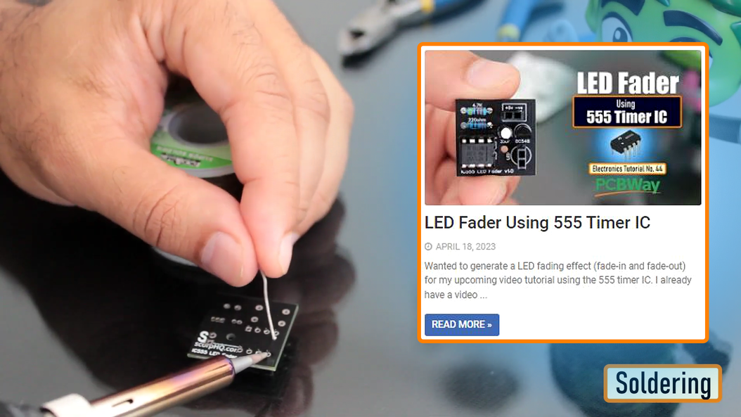


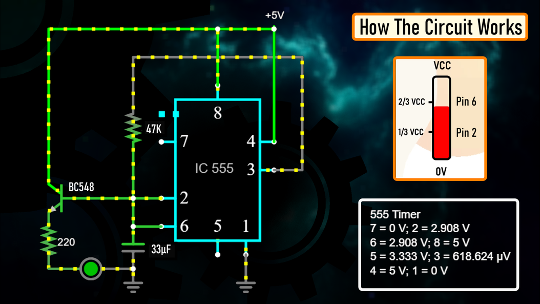

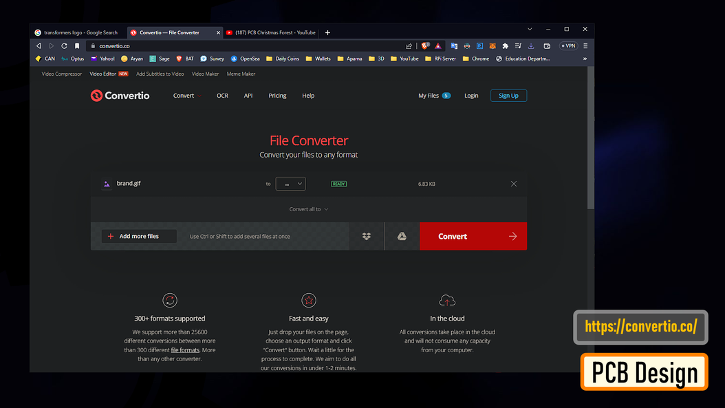


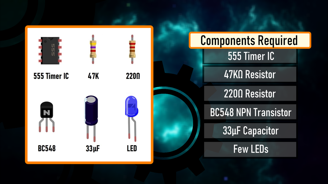


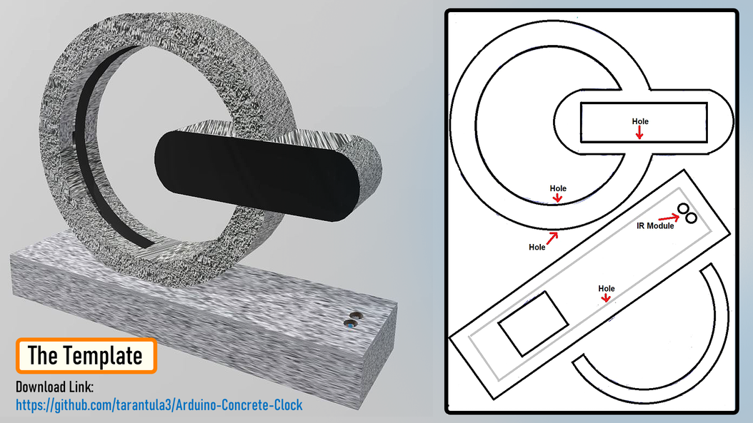


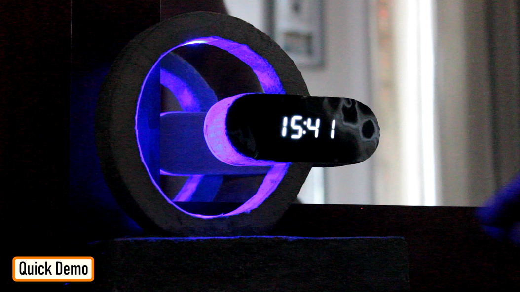


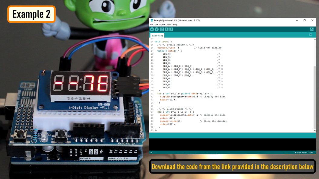


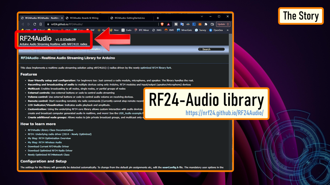


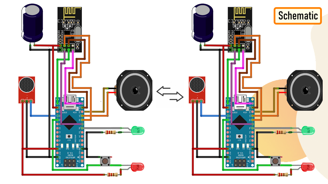


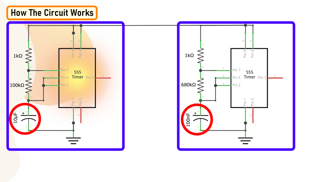


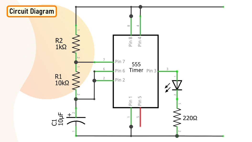
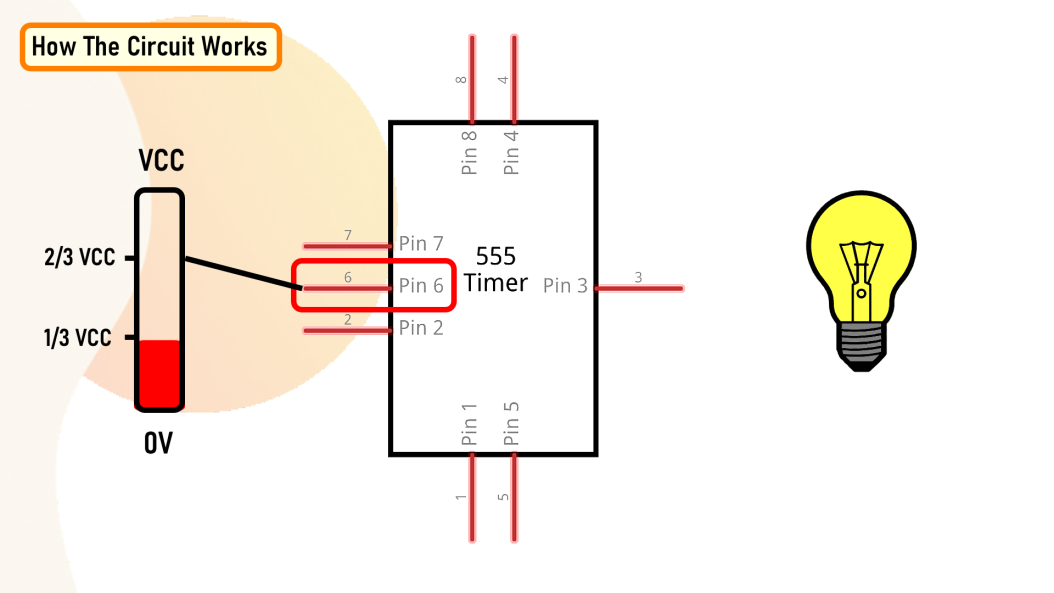


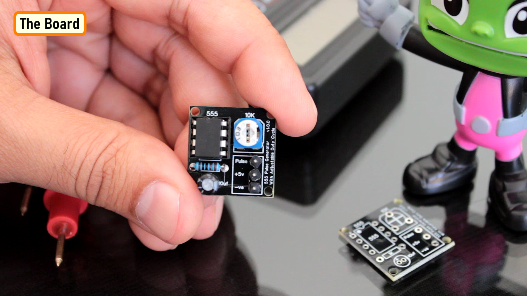


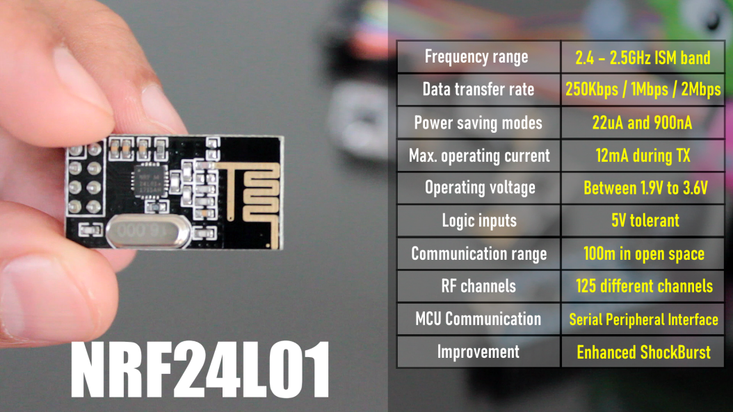


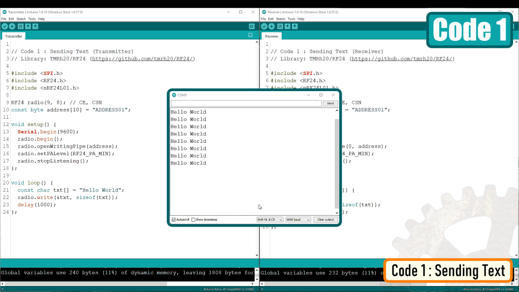


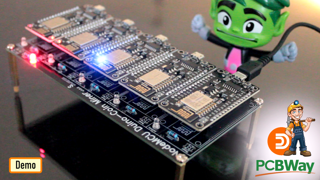


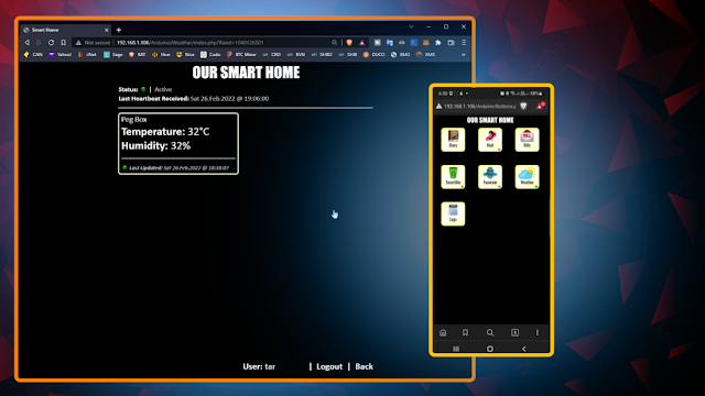


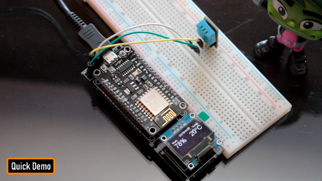


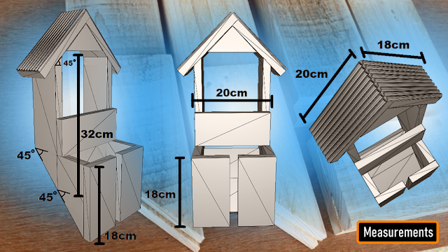
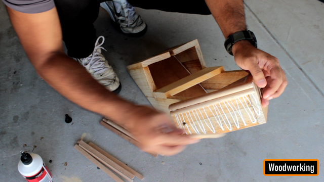
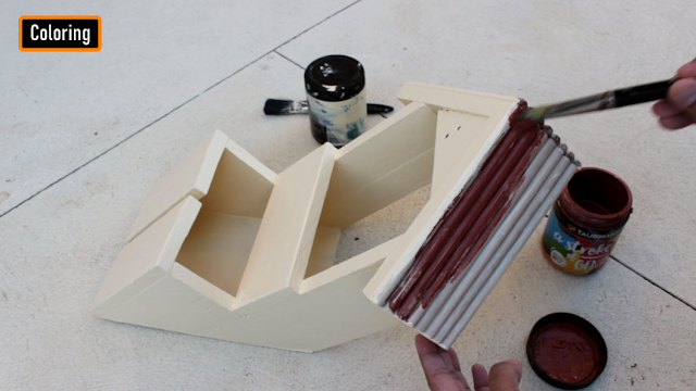


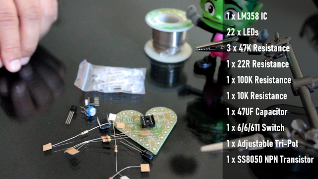
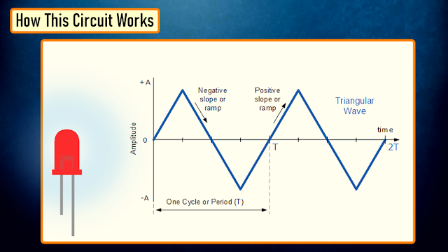
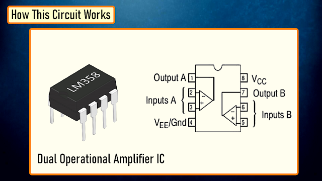
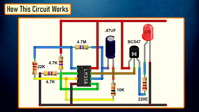

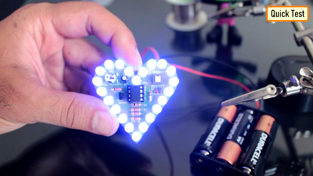


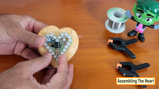
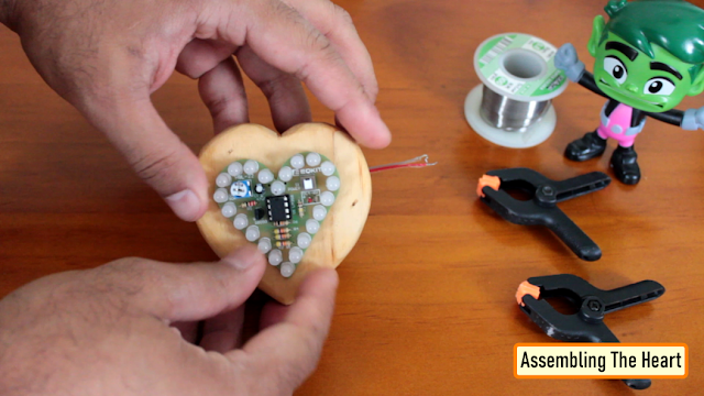
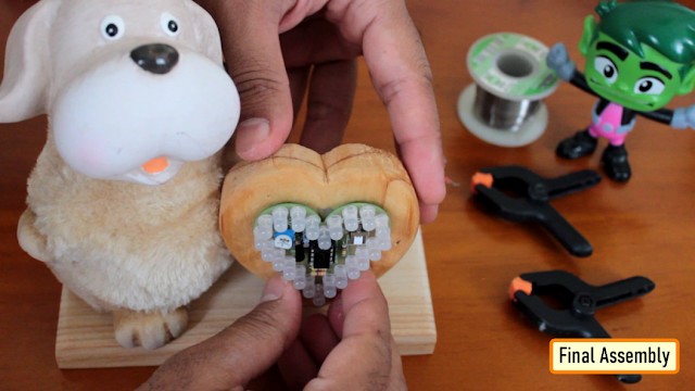

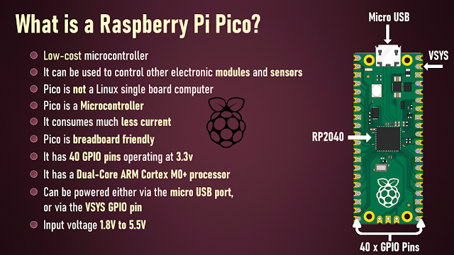
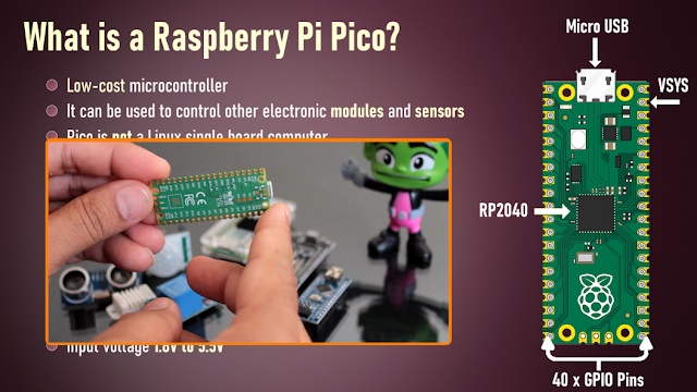
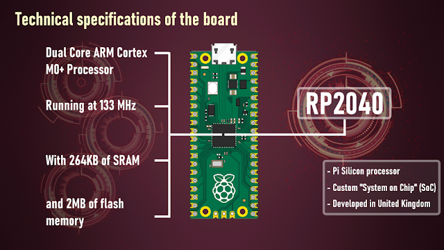
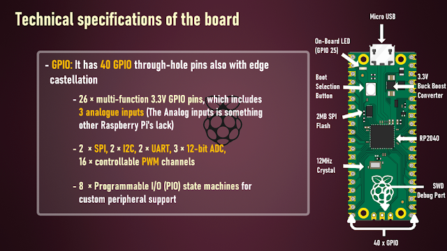
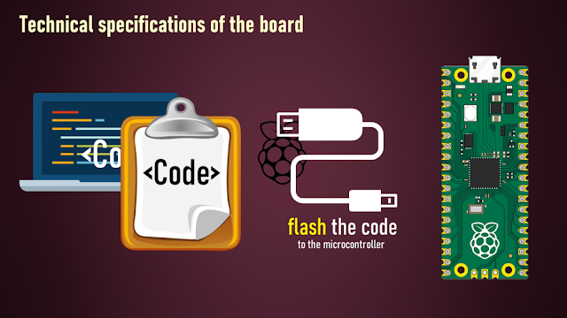
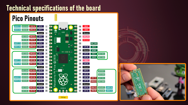


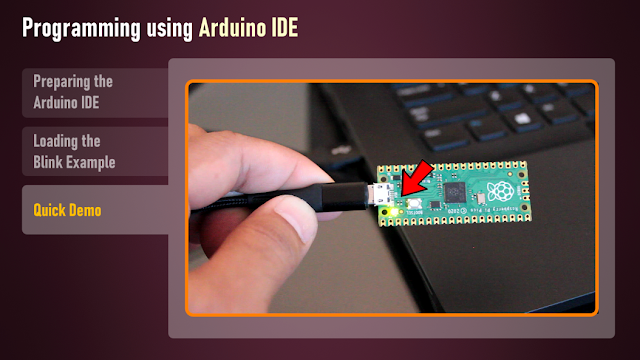


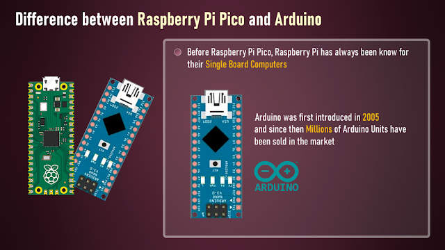

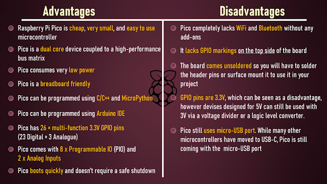
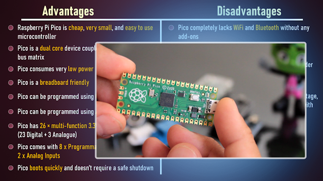

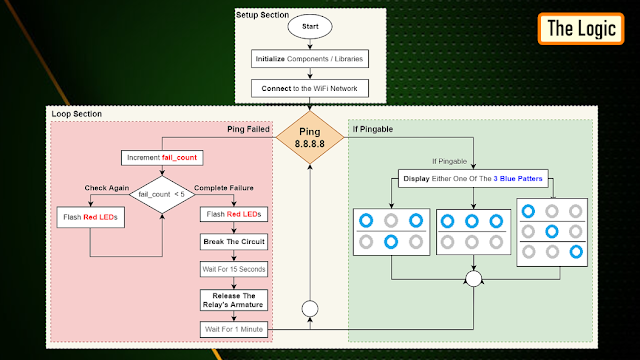


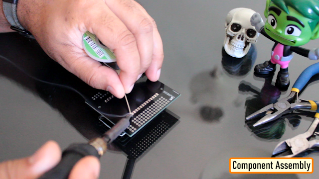


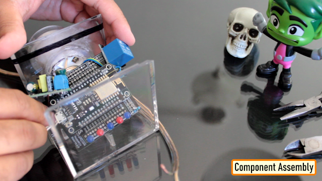


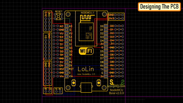
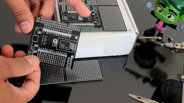
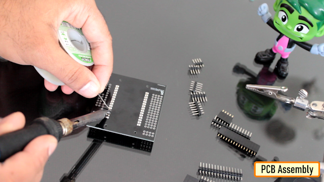
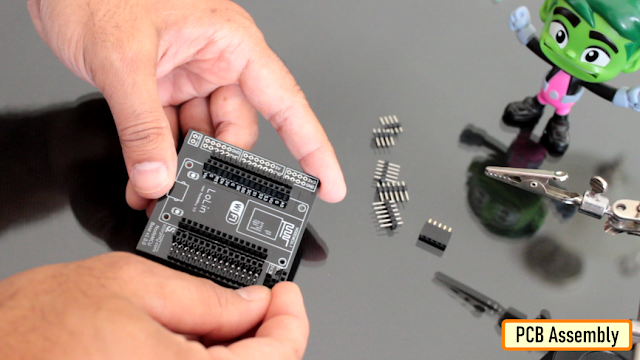
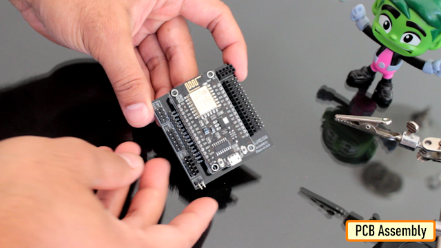
NodeMCU Based: 3D Printed Indoor Gauge Thermometer
in Electronics chit chat
Posted
Had some time this weekend and a desire to create something new and interesting, so went ahead and created an Arduino/NodeMCU based indoor dial thermometer. This device displays the temperature in degree centigrade on a D-Shaped Gauge as well as on a 7-Segment display.
In addition to that, it also saves the temperature and humidity readings in a MySQL DataBase hosted on a home based Raspberry Pi Server. The data is then displayed using the "Our Smart Home" app.
Awards
Components Required
For this project we need:
Circuit Diagram
The circuit is very simple. Connect the ULN2003 driver board’s IN1, IN2, IN3 and IN4 to the NodeMCUs digital pins D0, D1, D2 and D3.
Then connect the OUT Pin of the DHT22 to the D5 Pin of NodeMCU.
After that connect the 2 x Display Modules to the microcontroller. We are going to use a Common Clock Pin D4 for both modules. Then connect the DIO of one of the modules to D6 (TEMP) and the other one to D7 (HUM) pins on the NodeMCU.
Important: Please avoid using the boot config pins D3, D4, D8 and the RTC pin D0 for the displays.
Now, on the D8 Pin we are going to connect the switch. This switch has a very important role in this circuit.
This switch acts as the 'home' or the 'starting point' of the stepper motor.
When the switch is open Pin D8 is connected to GND through the pull-down resistor and we read a LOW. When the switch is closed, Pin D8 connects to 3.3v pin of NodeMCU and we read a HIGH.
When the 'temperature changes' or the 'device boots up', the pointer starts moving 'counterclockwise'. As soon as the pointer hits the home position, Pin D8 reads HIGH and the logic moves the pointer 'clockwise' to display the temperature on the gauge as read by the DHT22 module.
The Code
The code starts by including all the necessary libraries.
Then it defines all the variables needed for setting up the WiFi connection.
Next, it assigns a static IP address to the ESP8266 (if you want to use DHCP then go ahead and delete these three lines from the code).
After that, it sets up the 2 x URLs that are needed for updating the heartbeat, temperature and humidity.
Before going ahead let's have a quick look at the 2 php files.
The "UpdateStutus.php" file uses an UPDATE query to update the timestamp of the device sending the request to the current epoch time and hence updating the heartbeat.
The "UpdateTemperature.php" uses an INSERT query to add a new row to the database with the current values of Temperature and Humidity.
This is what is written to the database and can be displayed using Google Charts, in my case, I am using the "Our Smart Home" app to display the data using php and JavaScript. Currently I am only displaying the data from the Study room and the Peg Box. To know more about my award winning "Peg Box" project please have a look at my electronics tutorial no. 34 "Peg Box with Temperature and Humidity Monitor using NodeMCU" (https://youtu.be/elH331NXPsU).
After that, I am defining all the variables required for reading and storing the value of temperature and humidity.
Next, I am defining all the variables and setting up any additional symbols required for displaying temperature and humidity on the TM1637 Display Module.
After that, I am defining the D8 pin of the NodeMCU as the reset switch pin. We will talk about this in detail in the following sections.
Next, I am setting up the Steps Per Revolution of the stepper motor as 2038 and then initializing the stepper library through pins D0 to D3.
One thing to note: since I need both clockwise and counterclockwise movements, I have to initialize the pins in the order shown on screen.
Then in the setup() section, first I am setting up the WiFi connection and then sending a heartbeat to the server. Then I am setting up the brightness of the 7-Segments to their max values followed by starting the dht module and finally setting the pin-mode of the switch to INPUT.
Now, in the loop() section I am reading the temperature using the Read_Temp() function and then sending the Temperature and Humidity values every 30 minutes and heartbeat every minute to the home server.
Next, you see the definition of the SendIamAlive() and SendTemperatureAndHumidity() functions which utilizes the WiFiConnect() function to send the values using the previously discussed URLs.
The Read_Temp() function reads the temperature and humidity and updates the 7-Segment displays and moves the pointer only if there is a change in the values.
The Move_Needle() function first sends the pointer to the home position using the Return_Home() function and then looks through and moves the pointer to the correct position until the stepCout is = STEPS.
The value of STEPS is calculated based on the "stepsPerRevolution" which we previously set it up as 2038.
So, 2038 / 2 (for half circle) = 1019
Now by dividing 1019 by 180 degrees we get the steps required to display each degree centigrade.
Now to display each degree centigrade we need 180/60 = 3 divisions.
Since our gauge starts from -10 and not 0 we also have to add the first 10 blocks which is (5.661 * 10 * 3) to our calculation.
That's it as easy as that.
3D Designing
Lets have a quick look at the 3D model of the project.
At the front, we have The Pointer, D-Shaped Dial, and the Temperature Scale on the dial.
Down at the bottom we have the Enclosure that will house the microcontroller and all other electronics components in it. The enclosure has a Lid to keep the electronic components safe and sound.
At the back, we have a pocket to hold the DHT22 Module, 3 x holes for the stepper motor, 2 x groves for the TM1637 Display Module and 2 x L-Shaped Brackets to hold the top Dial to the bottom Enclosure.
3D Printing
Once the 3D models were sorted, it was time for me to fire up my 3D printing oven and start printing these 3D models.
I used:
- 1.75mm Cold White PLA Filament, and printed the models with
- 0.2mm
- with 0% infill
- and with support.
As we all know, 3D printing is the process that uses computer-aided design or CAD, to create objects layer by layer.
3D printing is not a new technology, it's been there since the 1980's, when Charles W. Hull invented the process and created the first 3D-printed part. Since then, the field of 3D printing has grown exponentially and holds countless possibilities. The 3D printing process fascinates me a lot and I sometimes love to sit near my printer and watch these layers getting printed.
The entire printing process took a little over 5 hours to complete and this is the final result.
Alright now, let's start gluing all the printed parts. I first superglued the L-Shaped Brackets to the dial followed by the pocket that will hold the DHT22 module. Then, I went ahead and screwed the bottom enclosure to the top section via the L-Shaped Brackets.
Breadboard Demo
Before adding the electronic bits to the 3D printed bits, let's do a quick test to make sure everything works as expected.
So, this 7-Segment display is displaying the temperature and the other one is displaying the humidity.
The needle is currently going round and round in circles as it has no idea where to stop. To stop the needle, and to send it the correct position on the gauge, I need to connect this red jumper cable connected to 3.3v to the D8 Pin of the NodeMCU.
Once I short the cable, the needle changes its direction and moves clockwise to display the temperature value read from the DHT22 module.
The temperature and humidity values are also sent to the 'Home Server' which are then displayed using the "Our Smart Home" app.
Coloring
Using Acrylic colors, I painted all the 3D printed parts of the project.
Assembling
Once the coloring is done, its now time for me to put all the electronic components together.
First I screwed the stepper motor to the back of the dial. Then, I gently pushed the DHT22 Module into its pocket at the back of the dial.
Now the interesting bit. As per our previous discussion, we are going to use a copper wire as a switch that will move the pointer to its correct position. The copper wire will be fed through these two holes from the back and will loop through this small pipe like structure in the front. A small cut will be made on the top exposed side of the copper wire.
Now on the pointer, we need to add a small piece of copper wire. When this copper bit touches the two copper wires on the pipe, it will complete the circuit and will send a HIGH to the system.
Next, I am hot gluing the two TM1637 7-Segment Display Modules to the back of the dial.
Once done, it's pretty much just a matter of soldering all the sensors to the NodeMCU as per our circuit diagram.
Final Demo
So, this is how my final setup looks like.
Once the device is turned on, the pointer moves counterclockwise until it touches the copper wires that acts like a switch. Upon touching the wires the pointer moves clockwise to display the temperature value read from the DHT22 module on the D-Shaped Gauge.
The temperature and humidity values are also displayed using 7-Segment Displays.
The values are also sent over WiFi to a Raspberry Pi Home Server and stored in a MySQL database. Using google charts, you can display the data using various different graph options. In my case, I am using the "Our Smart Home" app to display the data using php and JavaScript.
Thanks for watching, please comment and let me know if there are any scopes of improvement.
Thanks
Thanks again for checking my post. I hope it helps you.
If you want to support me subscribe to my YouTube Channel: https://www.youtube.com/user/tarantula3
Video: Watch
Full Blog Post: Visit
Thermometer STLs: Download
Peg Box: Watch
How To Wire A Pushbutton: View
Stepper Motor Specs: View
Support My Work
Thanks, ca gain in my next tutorial.