
Ashish Adhikari
-
Posts
41 -
Joined
-
Last visited
-
Days Won
2
Content Type
Profiles
Forums
Events
Posts posted by Ashish Adhikari
-
-
In this tutorial I am going to show you guys how to make an Arduino or NodeMCU based Weather Station using DHT11 or DHT22 temperature and humidity sensor and display it using an OLED Display.
DHT11 vs DHT22
 The DHT11 and DHT22 are both low-cost very basic and slow temperature and humidity sensors which can be used for basic data logging.Despite being slower, they are very stable and consumes low power and provides relatively high measurement accuracy. The single-bus digital signal is output through a built-in ADC which is easy to read using any microcontroller. Single bus interface saves the I/O resources of any microcontroller board.The operating voltage is between 3.3V to 5V and the sampling period for DHT11 is 1Hz or one reading every second and for DHT22 is 0.5Hz or one reading every two seconds. Hence, you can not query them more than once every second or two.
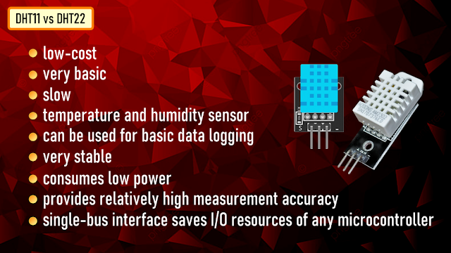 The DHT sensors are made of two parts, a capacitive humidity sensor and a Negative Temperature Coefficient or NTC temperature sensor (or thermistor).The NTC temperature sensor is actually a variable resistor whose resistance decreases with increase in the temperature.For measuring humidity, two electrodes with a moisture holding substrate between them is used. When the humidity changes, the conductivity of the substrate changes or in other words the resistance between these electrodes changes. This change in resistance is measured and processed and is sent to the microcontroller.A very basic chip inside the sensor does the analog to digital conversion and spits out a digital signal which is read using a microcontroller.
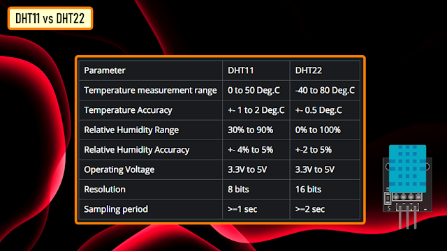 Here is a comparison chart of the two sensors. Looking at this it is very clear that DHT22 outshines the DHT11 in every aspect.However, if accuracy is your concern, and you are ready to pay a bit higher price, go for DHT22. Otherwise, DHT11 should be good enough for you.
OLED Display
 OLED or organic light-emitting diode is a light-emitting diode (LED) in which the emissive electroluminescent layer is a film of organic compound (millions of small LED lights) that emits light in response to an electric current.OLEDs are used to create digital displays in devices such as television screens, computer monitors, portable systems such as mobile phones, hand-held game consoles and PDAs. An OLED display works without a backlight because it emits visible light.There are many types of OLED displays available in the market based on their:
- Sizes
- Color
- Brands
- Protocol
- SPI (Serial Peripheral Interface) or I2C
- Passive-matrix (PMOLED) or active-matrix (AMOLED) control scheme
To know more about OLED Display and to know how to connect multiple OLED Displays using TCA9548 multiplexer check out my tutorial number 7OLED Display with Arduino and NodeMCU link is in the description below: https://www.youtube.com/watch?v=_e_0HJY0uIoLets have a closer at these two displays.At the back of these displays there are heaps of SMD capacitors and resistors soldered on-board; but, since its an I2C device we only care about these 2 pins (SCL and SDA)The display connects to Arduino using only four wires – two for power (VCC and GND) and two for data (serial clock SCL and serial data SDA), making the wiring very simple. The data connection is I2C (I²C, IIC or Inter-Integrated Circuit) and this interface is also called TWI (Two Wire Interface).The on-board pins can be in different order, so always triple check before hooking it up to your project.Operating voltage is between 3v to 5v but, it is best to use the guidance from the manufacturer's datasheet.Sometimes we need to use 2 displays in our projects. So, how can we achieve this?The trick is to have a configurable address on your display. This unit has a configurable address between 0x78 and 0x7A. Just by unsoldering the 0Ohm resistor from one side and hoking it up to the other side or just by putting a global solder we can change the address.In picture these displays look very big. But, practically speaking they are tiny. They are made of 128 x 32/64 individual OLED pixels and do not require any back-light. Just have a look at this and see how small it is. Even though they are small they can be very useful in any electronic projects.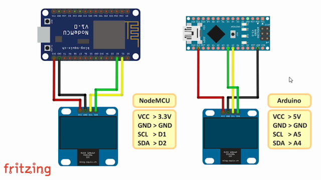 This is how an OLED Display is connected to either Arduino or NodeMCU.
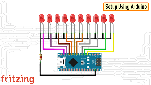
Setup Using Arduino
 The setup using either Arduino or NodeMCU is very simple.We just need to connect the OLED to the I2C Pins and the Temperature and Humidity sensor to any one of the Digital pins.In this setup I have connected the OLED to A5 and A4 and the Sensor to D8.
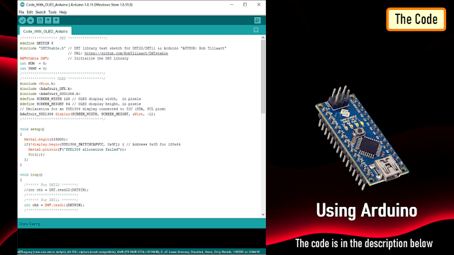
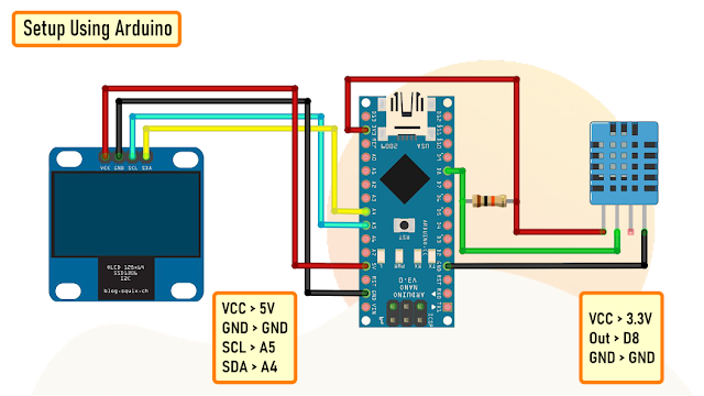 Now, lets look at the code. Lets start by including the DHT and OLED libraries.Then, in the setup section we initialize the display and then in the loop section we loop through every 2 seconds and read the sensor and display the result on the OLED display.
 Here is a quick demo using Arduino.
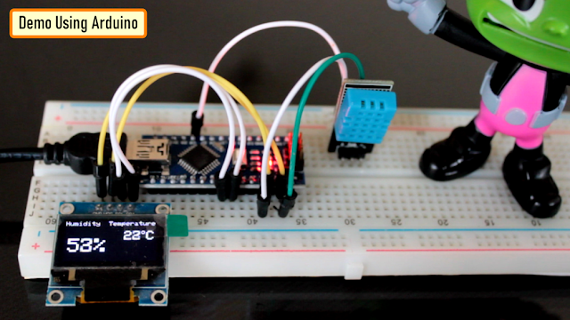
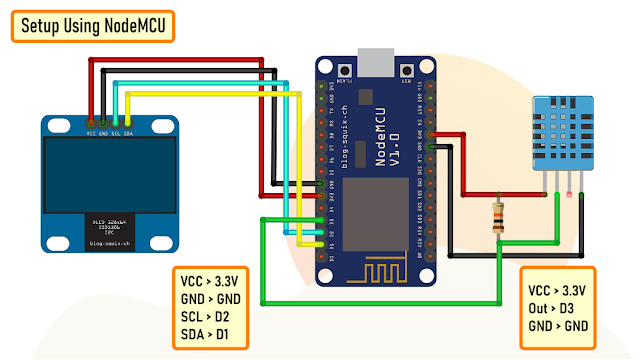
Setup Using NodeMCU
 Same as the previous setup, the OLED display connects to the NodeMCU using D2 and D1 pins and the Sensor connects to the D3 pin.
 The code starts by including the DHT and OLED libraries.Then, in the setup section we initialize the display and then in the loop section we loop through every 2 seconds and read the sensor and display the result on the OLED display.
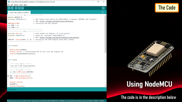 So, this is how the actual setup looks like.
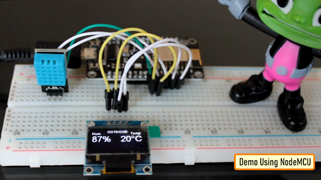
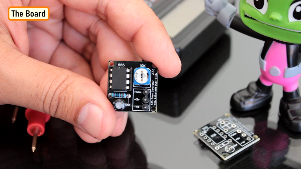
The Board
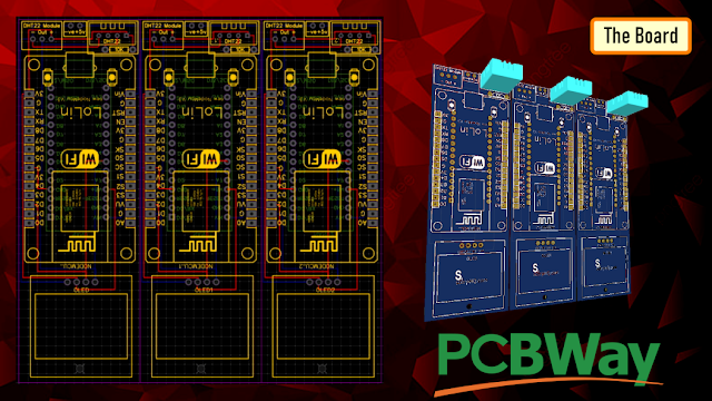 So, this is how my board looks like in 2d and 3d.There are 3 breakout boards in this 100cm x 100cm assembly. Each board can be used with either Arduino or NodeMCU and DHT11 or DHT22 sensor or sensor module.
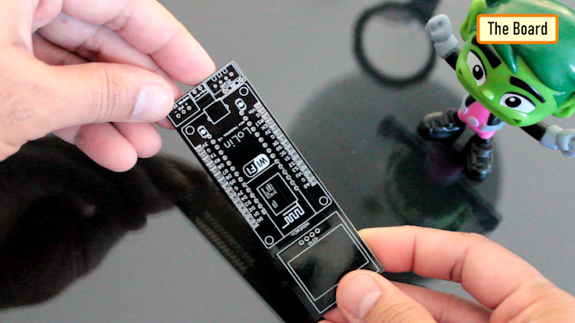 The Board can be used with either NodeMCU or Arduino Nano.Temperature and humidity readings can be collected using either a DHT11 or DHT22 Module or by using one of these sensors with a 10K resistor.The bottom section of the board is for the OLED display. The attached gerber is bit different from what you see on screen. I made some modifications in the final version and moved the sensors a bit far from the microcontrollers.
Soldering
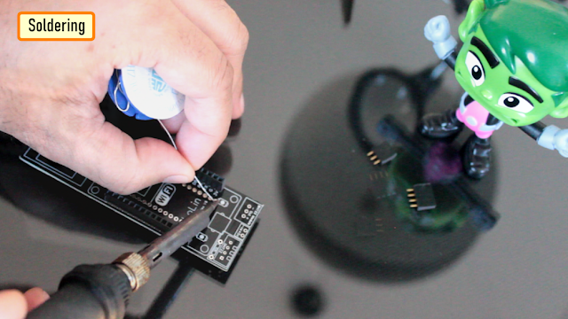 Since I care a lot about my Sensors and Microcontrollers I am not soldering them directly to the board. Instead I am soldering, female pin headers to the board which will house all the sensors and microcontrollers.Just for the sake of this video I am soldering female pin headers on both sides for Arduino and NodeMCU. However, In your setup you will need either Arduino or NodeMCU.
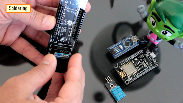
Final Demo
 Lets first test this with an Arduino.Now, lets test this setup using a NodeMCU board.Looks perfect, I am going to use this board in my next project where I will be sending Temperature and Humidity readings to my Raspberry Pi based home server where I will be storing it in a MySQL database, so stay tuned....
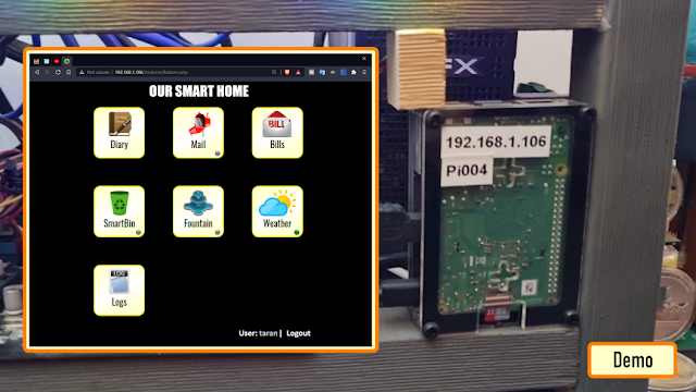
Thanks
Thanks again for checking my post. I hope it helps you.If you want to support me subscribe to my YouTube Channel: https://www.youtube.com/user/tarantula3Blog Posts:1. DHT11 & DHT22: https://diyfactory007.blogspot.com/2021/09/temperature-and-humidity-monitor-using.html2. OLED Tutorial: https://diyfactory007.blogspot.com/2018/07/oled-i2c-display-arduinonodemcu-tutorial.htmlVideo references:1. DHT11 & DHT22: https://youtu.be/w5tBtHsl7b42. OLED Tutorial: https://www.youtube.com/watch?v=_e_0HJY0uIoCode:Code_With_OLED_Arduino : https://drive.google.com/file/d/1EEdhPuUiy8xWSD_s41iYAccTz8w-QF9C/view?usp=sharingCode_With_OLED_NodeMCU : https://drive.google.com/file/d/1WFtdyu90gAqxhJq-Pur7w8fvXuuM85lt/view?usp=sharingCode_With_PHP_NodeMCU : https://drive.google.com/file/d/1bT08x-h39NS1LdkCCH2F3ySG3hrht9U4/view?usp=sharingCode_With_PHP_OLED_NodeMCU: https://drive.google.com/file/d/1ji5TEvLbhe3GJiDgQRowDws5PdZZXqf9/view?usp=sharingLibraries:"DHTStable.h" : https://github.com/RobTillaart/DHTstable"SSD1306.h" : https://github.com/squix78/esp8266-oled-ssd1306Adafruit display library: https://github.com/adafruit/Adafruit_SSD1306Adafruit GFX library: https://github.com/adafruit/Adafruit-GFX-LibrarySupport My Work:BTC: 1M1PdxVxSTPLoMK91XnvEPksVuAa4J4dDpLTC: MQFkVkWimYngMwp5SMuSbMP4ADStjysstmDOGE: DDe7Fws24zf7acZevoT8uERnmisiHwR5stETH: 0x939aa4e13ecb4b46663c8017986abc0d204cde60BAT: 0x939aa4e13ecb4b46663c8017986abc0d204cde60LBC: bZ8ANEJFsd2MNFfpoxBhtFNPboh7PmD7M2Thanks, ca again in my next tutorial. -
The 555 timer IC is an integrated circuit that is used in a variety of timer circuits, pulse generators and oscillator applications. The heart of the module is the 555 timer IC that is wired as an astable multivibrator, generating pulses from about 4Hz to 1.3Khz.
This circuit can be used in any project, that requires positive pulses.
To demonstrate the operation, a LED is used at the output of the IC to show the visual indication of the output pulses.
The output frequency of pulses can be adjusted using a potentiometer. The circuit can be operated from any voltage between 5 to 15 volt DC.
Items Required

For this project we need:
- 1 x 555 Timer IC
- 1 x 10µF Capacitor
- 1 x 1kΩ Resistance and a
- 1 x 10kΩ Potentiometer
Circuit Diagram

The circuit is very simple.
By connecting pin 2 and 6 we put the 555 timer in astable mode. Astable mode causes the 555 timer to re-trigger itself, producing a stream of pulses [PWM Signals] as long as its hooked up to a power supply.
Pin number 3 is the output pin. By changing the values of R1, R2, and C3 we can change the frequency of output pulses generated at pin number 3.
How It Works
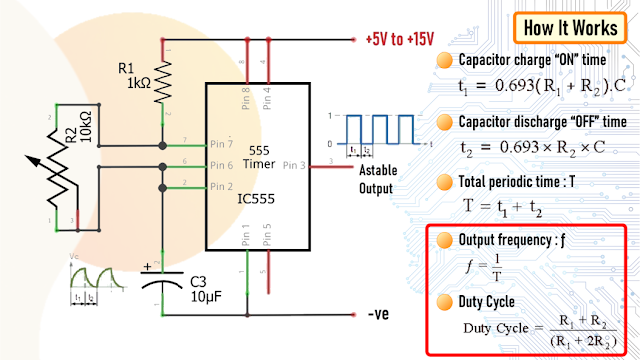
The working voltage of the circuit is between 5V~15V DC.
As previously discussed 555 timer generates PWM signals when set up in an astable mode by connecting the pin 2 and 6 together.
During each cycle capacitor C3 charges up through both R1 and R2 resistors but discharges itself only through resistor R2 as the other side of R2 is connected to the discharge terminal pin 7.
Changing the values of R1, R2, and C3 will change the frequency of output pulses, or different duty cycle of the square wave coming out of pin 3.
By changing the value of R2 we can change the duration of the OFF cycle.
In this setup the ON time depends on the resistor R1, the left side of the pot and the capacitor C3, while the OFF time depends on the capacitor C3 and the right side of the pot.

Now, lets calculate the output frequency and the duty cycle of the output waveform.
In my setup I have resistance R1 = 1kΩ, R2 = 10kΩ and capacitor C = 10uF
There are many online calculators to calculate this online. I will provide a link to one of the astable calculators in the description below: https://ohmslawcalculator.com/555-astable-calculator
Lets first calculate the value of t1 or the 'capacitor charge “ON” time which is 0.693(R1 + R2 ) * C3. Putting the values together we get 76.23 milliseconds.
Now, for capacitor discharge “OFF” time or t2 we need to multiply 0.693 to R2 and C3, which then gives us a value of 69.3 milliseconds.
Next, the total periodic time T is equal to t1 + t2 which comes out to be 145.53 milliseconds.

The output frequency, ƒ is therefore comes out to be to 6.871Hz.

Which gives a duty cycle value of 52.38%
If you want to have more control over the charging and discharging use a higher value for R2 (100K) and lower value for R1 (1K). That way you will have 99% control over the charging and discharging resistance in the circuit.
The maximum output current of this IC is 200mA therefore to drive a higher current load of up to 1A we have to use a transistor like the BD135.
For driving a much higher current than 1A you can use other high current transistors like TIP31, 2N3055, etc. with a good heatsink. TIP122 can only go up to about 1.5 amps without a heatsink, however it can go up to 5 amps with a good heatsink. IRLB8743 FET is good to around 20 amps without a heatsink.
The Board
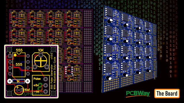 So this is how my board looks like. There are 16 breakout boards in this 100cm x 100cm assembly. You can download the gerber file from the link below and order it from PCBWay.
Soldering
 Lets start by soldering the IC Base to the board. Then lets solder the potentiometer to the board. After that lets solder the R1 resistor to the board followed by the C3 capacitor to the circuit board. Once done lets place the 555 timer IC to the IC base.
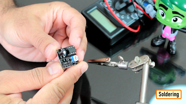 To conclude I have soldered 3 x Male pin headers to the board.
Demo
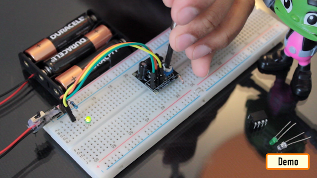 So, this is the final appearance of the board. I am adjusting the output frequency of pulses using the 10K potentiometer.
Applications and Uses
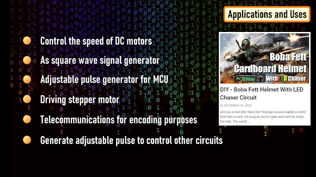
- This circuit can be used to control the speed of DC motors
- As square wave signal generator
- Adjustable pulse generator for MCU
- Driving stepper motor
- Telecommunications for encoding purposes
- Generate adjustable pulse to control other circuits
I have used this in few of my projects like:
- DIY - Boba Fett Helmet With LED Chaser Circuit : https://youtu.be/vtO_GD0SS2s
- LED Chaser Circuits Using IC4017 and Arduino : https://youtu.be/F6V1AjESWbU
- DIY - LAN CABLE TESTER : https://youtu.be/PSK5Aa-byHA
Thanks
Thanks again for checking my post. I hope it helps you.If you want to support me subscribe to my YouTube Channel: https://www.youtube.com/user/tarantula3
Full Blog Post: https://diy-projects4u.blogspot.com/2021/07/555-pulse-generator-module-how-it-works.html
Video: https://youtu.be/bMAnipPOjFo
Related Videos:
1. DIY - Boba Fett Helmet With LED Chaser Circuit : https://youtu.be/vtO_GD0SS2s
2. LED Chaser Circuits Using IC4017 and Arduino : https://youtu.be/F6V1AjESWbU
3. DIY - LAN CABLE TESTER : https://youtu.be/PSK5Aa-byHA
Gerber File: https://drive.google.com/file/d/1YE5vznhAcQx2cmlXouRhn2yxZB3Lb2RK/view?usp=sharing
Calculator: https://drive.google.com/file/d/17dTw22opXIw8WI4-knUZu4rr6k-6zlxV/view?usp=sharing
Schema: https://drive.google.com/file/d/1K635sLu-J3UQzEibjANlfm8ywCgy4tJ0/view?usp=sharing
Support My Work
- BTC: 1M1PdxVxSTPLoMK91XnvEPksVuAa4J4dDp
- LTC: MQFkVkWimYngMwp5SMuSbMP4ADStjysstm
- DOGE: DDe7Fws24zf7acZevoT8uERnmisiHwR5st
- ETH: 0x939aa4e13ecb4b46663c8017986abc0d204cde60
- BAT: 0x939aa4e13ecb4b46663c8017986abc0d204cde60
- LBC: bZ8ANEJFsd2MNFfpoxBhtFNPboh7PmD7M2
Thanks, ca again in my next tutorial.
-
Whether you prefer to unwind the evening with a good book, play games on your phone, or wanna have some cozy time with your partner, the right bedside lighting can make a lot of difference.
In this project, I am going to make a touchless multipurpose bedside lamp, which will also include a digital clock, two power-ports and a USB charger.
Sponsors
This video is sponsored by PCBWay.
Woodwork

 Lets start the project by sanding a pallet planks to give it a nice and smooth texture.Then, lets drill 3 holes for the top and the 2 sides of the night lamp.After drilling the holes lets extract the sides from the plank using a chop-saw or a hand-saw.
My pallet plank is 9.5cm wide and the lamp will be square in shape. So, rest of the measurements are based on that.

Assembly
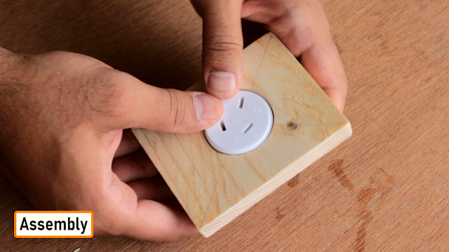
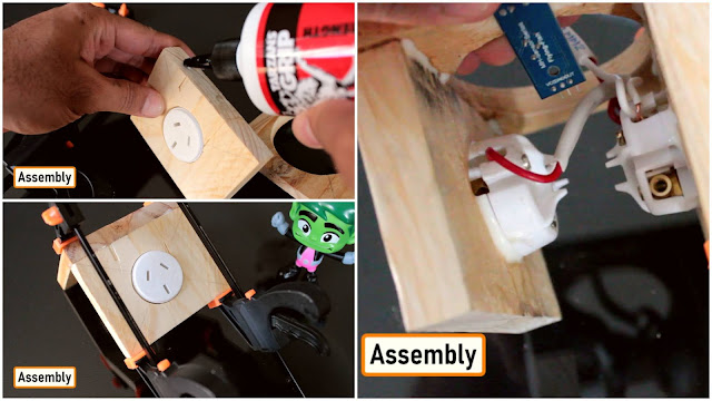
Once all the sides were ready its was time for me to join them all together.
First of all I am getting the 2 x sides ready by gluing the power sockets into the holes.
Next, I drilled 2x more holes for the IR sensor.
If you want to know more about IR sensors please check out my "Tutorial No 21 : DIY - IR Module : https://www.youtube.com/watch?v=_M8FQIPi1qk"
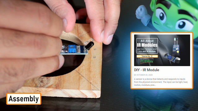
Next, one by one using wood glue I am joining the 2 x sides to the top of the lamp. At first I thought of using nails to join the sides, but soon I realized that by all means it was a very bad idea. Before gluing the 2nd side I connected the two power ports together using a copper wire.
Alright now, Lets look at the electronics bit.
Electronics

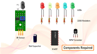
For the electronics bit we need:
- 1 x IR Sensor
- 5 x Colored LEDs
- 5 x 220Ω Resistors
- 1 x 10uf Capacitor
- 5 x 2N2222 NPN Transistor
- 1 x 4017 IC
4017 is a Decade Counter IC, it can count from 0 to 10. When a clock signal is received on Pin-14 the output turns to high one by one in a sequence.
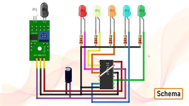
The signal from the IR-Sensor clocks the 4017 decade counter. Whenever a pulse is received at the clock input of IC, the counter increments the count and activates the corresponding output PIN. In our project we only need to count upto 5 so the 6th output from Pin-5 will be given to the Reset Pin-15. Sending a high signal to Pin-15 will reset the counter and it will skip counting the rest of the numbers and will start from the beginning. A capacitor is added to filter out too frequent detection of object by the IR sensor.
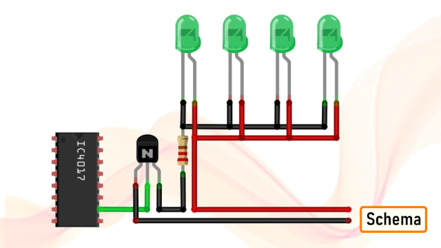
To add a cluster of LEDs to the circuit, we just need to feed the output from the IC to a transistor and the cluster can then be connect to the transistor. Similar to this setup.
Top - Soldering Components
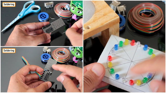
So, now lets start putting the components together. Lets solder the IC base followed by the 5 x NPN Transistors. Then, lets solder the 220Ω Resistors and the 10uf Capacitor to the board. I also added few pin headers to the board, 3 for the IR Sensor and 2 for the 5v power supply. The transistors are connected to the ribbon of wire which then connects to the cluster of LEDs that will slide under the top section.
Before putting the circuit into production lets do a quick test. Bang, nailed it..
Front - Clock
For the front bit I am using a 4-Bits DIY Electronic Digital Clock which I bought from AliExpress for just AU$2.40.
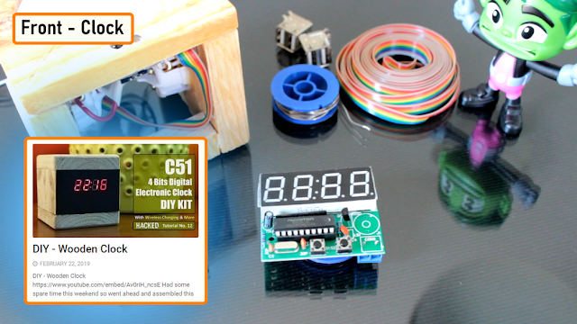
If you want to know more about this clock please checkout my "Tutorial No 12 : DIY - Wooden Clock : https://youtu.be/Av0riH_ncsE "
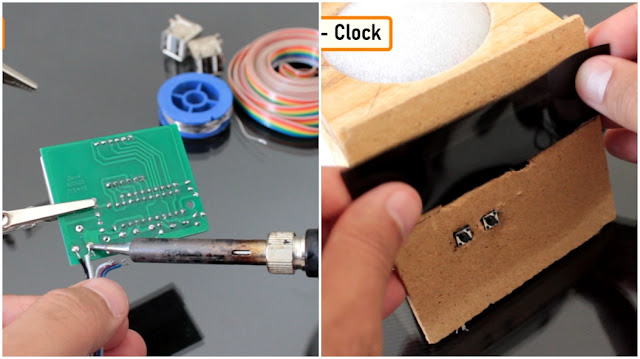
I moved the 2 push button switches from the board to the front panel of this lamp. My initial plan was to cover this entire setup with timber veneer sheet. However, I could not find one that was thin enough to not completely hide the 7-segment display. So, I ended up putting a black plastic film over the 7-segment display.
Back - USB Port
The back bit will host the USB ports and will also have a hole for the AC power chord.
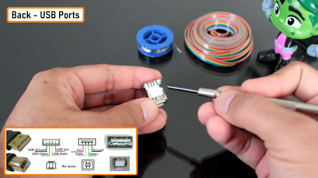
Lets have a look at this USB port. When I am holding a USB port upside down the left most pin is the -ve pin and the rightmost is the +ve pin. The middle two are the data pins which I am not going to use in this project.
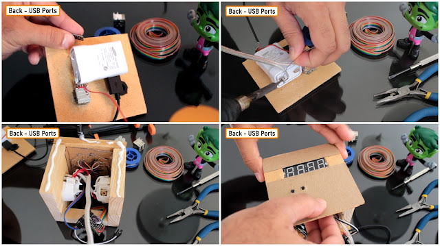
I used a Rubber Grommet to safeguard the power chord's hole.
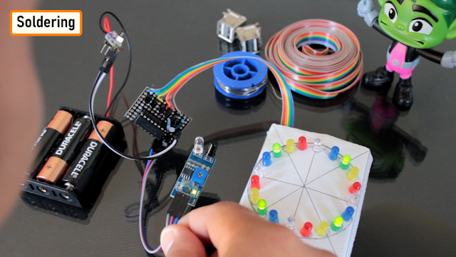
To power the electronics bit I am using a USB charger. I glued the USB charger to the back bit of the lamp. I soldered the power supply cable to the USB charger and then hot-glued to protect it from touching the other electrical and electronic components.
Then I glued the back and the front plates of the lamp to the wooden frame. I soldered all the electronics components to the USB charger.
Bottom - Power Supply

The bottom bit will hold the AC Power Cables. Since I don't want the AC cables to float around and cause short circuits inside the lamp, I screwed them to the base of the lamp.
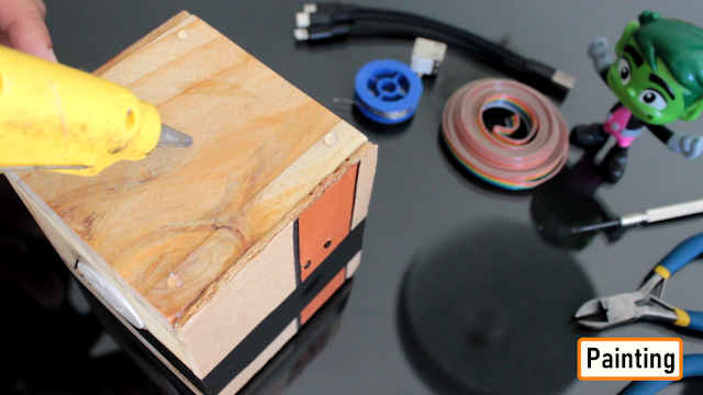
Painting
I painted the lamp a little bit to give it a modern look. Next, I superglued the black plastic film and painted its edges to match the whole setup.
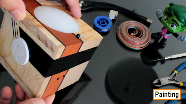
To finalize the setup, I added a bit of hot-glue to the bottom of the lamp. These glue drops will stop this lamp from scratching my bedside table top.
Demo
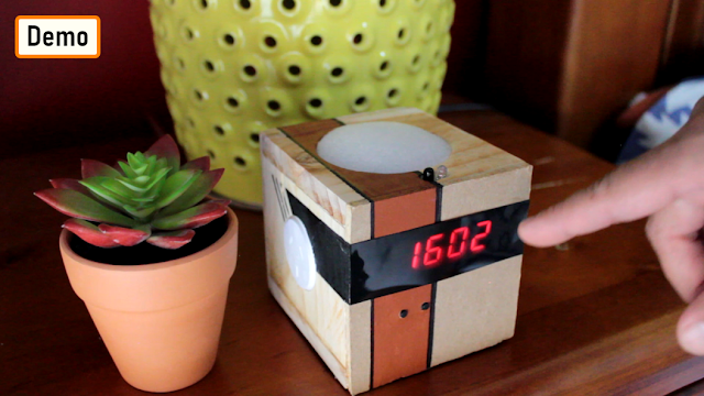 Covid has taught us many things, it has changed our life.
This project was an attempt to make things touchless. Hope you guys enjoyed it.
Thanks
Thanks again for checking my post. I hope it helps you.
If you want to support me subscribe to my YouTube Channel: https://www.youtube.com/user/tarantula3
Full Blog Post: https://diyfactory007.blogspot.com/2021/05/touchless-multifunctional-bedside-lamp.html
Video: https://youtu.be/r1r9jIgtcEk
Links:
Tutorial No 21 : DIY - IR Module :: https://www.youtube.com/watch?v=_M8FQIPi1qk
Tutorial No 12 : DIY - Wooden Clock :: https://youtu.be/Av0riH_ncsE
Music: Nocturne - Asher Fulero
Music: Simple - Patrick Patrikios
Support Me:
- BTC: 1M1PdxVxSTPLoMK91XnvEPksVuAa4J4dDp
- LTC: MQFkVkWimYngMwp5SMuSbMP4ADStjysstm
- DOGE: DDe7Fws24zf7acZevoT8uERnmisiHwR5st
- ETH: 0x939aa4e13ecb4b46663c8017986abc0d204cde60
- BAT: 0x939aa4e13ecb4b46663c8017986abc0d204cde60
- LBC: bZ8ANEJFsd2MNFfpoxBhtFNPboh7PmD7M2
Thanks, ca again in my next tutorial.
-
Have an awesome project in mind using some LEDs. In that project I will be using some LED Fading Effect and few LED Chaser Circuits. But before jumping onto that, I thought I should create a short tutorial and show you guys how to fade a LED with or without an Arduino automatically or manually using a potentiometer.
Video: https://youtu.be/IIUsdICycOwSponsors
 This video is sponsored by PCBWay.PCBway: only $5 for 10 pcbs from https://www.pcbway.com/?from=CZcouplePCBWay specialize in manufacturing of very high quality, low-volume, colored PCBs at a very budgetary price. In addition to the standard PCBs, you can also order Advanced PCBs, Aluminum PCBs, FPC/Rigid-flex PCBs. They also provide PCB assembly and other related service which can meet your needs to the greatest extent.The ordering process from PCBWay is very easy. Once I had my design ready, I just had to upload the gerber file to the PCBWay's website and select the type, color and any other customization that I want and then just send it for fabrication.For my project, I choose the black color. PCBWay ships from china to most of the countries of the world within 3 to 7 business days. Talking about the quality, its absolutely mind-blowing.
Without Arduino
 Lets first create the fader circuit without an Arduino. The base of this circuit is an operational amplifier IC named LM358. In this circuit, initially, the LED slowly glows with increasing brightness & after reaching its maximum brightness, the LED slowly dims its brightness and the process continues.
Automatic Fading
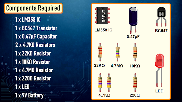
Components Required
For the Non-Arduino bit we need:- 1 x LM358 IC
- 1 x BC547 Transistor
- 1 x 0.47µF Capacitor
- 2 x 4.7KΩ Resistors
- 1 x 22KΩ Resistor
- 1 x 10KΩ Resistor
- 1 x 4.7MΩ Resistor
- 1 x 220Ω Resistor
- 1 x LED
- and a 9V Battery
How This Circuit Works
To get the fading effect we need to generate a series of triangular waves.Because of the triangular waves, the LED starts glowing slowly and then slowly dims off and the cycle continues.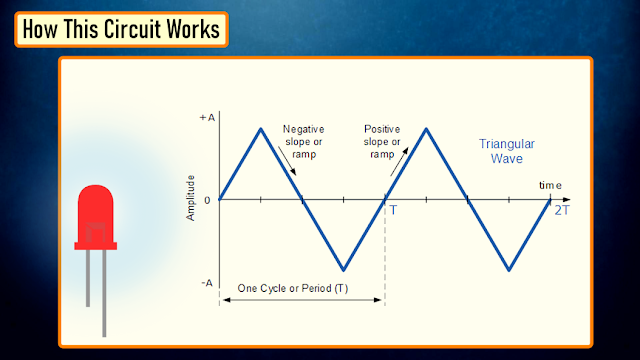 This setup is done using the LM358 IC. LM358 is a dual operational amplifier (Op-Amp) IC, integrated with two op-amps powered by a common power supply. Pins 1, 2, and 3 are one op-amp channel, and pins 5, 6, and 7 are the 2nd op-amp channel.
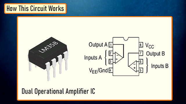 As the capacitor charges and discharges the state of the PIN 3 switches from high to low and based on that the PIN 2 of the op-amp obtains the desire output. If you want to know more about this IC, please check out my "Tutorial No 21 : DIY - IR Module" : https://youtu.be/_M8FQIPi1qk.
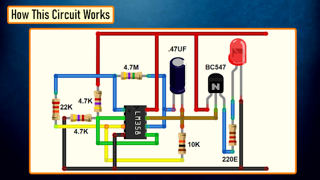 So, basically the op-amp here is used for voltage level detection. In this circuit, we are applying a voltage on positive pin (PIN-3) and the voltage to be detected is applied at negative pin (PIN-2).The transistor acts as a signal amplifier. You will need this if you are attaching a cluster of LEDs however for just 1 LED you can simply remove it.
The Board
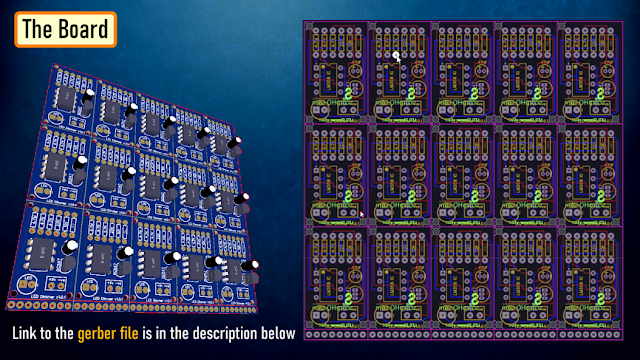 So, this is how my board looks like in 2D and 3D.There are 15 breakout-boards in this 100cm x 100cm assembly.
Component Assembly
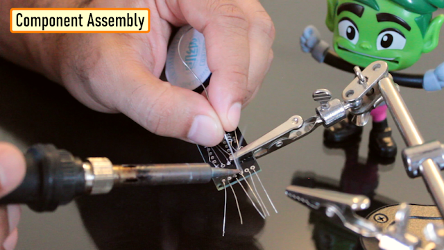 Now, lets solder all the components to the board. Lets first solder all the resistances to the board. Then lets solder the transistor followed by the capacitor to the board. After that lets solder the LED and the female pin header. To conclude the setup, lets solder the IC base and then install the IC into it.
Demo
 So, this is how it looks like.Good thing about LEDs is that they can be easily controlled as compared to the traditional light bulbs. Which means you can easily change their intensity based on your need. Just by making a slight modification to this circuit you can change the brightness of a LED Lamp when someone walks in or out of a room.
Manual Fading Using PWM
Now, if you want to get the same dimming effect but want to manually control the intensity, you will have to find a way to modulate the pulse sent to the LED or group of LEDs using a potentiometer. I am going to do this by generating PWM Signals.What is PWM?
Pulse Width Modulation, or PWM, is a technique for getting analog results with digital means. PWM value varies from 0 to 255. The bigger the value of PWM, the brighter the LED is and vice versa.- If PWM = 0, it is same as GND, so the LED will be OFF- If PWM = 255, it is same as VCC, so the LED will be fully ON
 To get varying analog values, you change, or modulate, that pulse-width. If you repeat this on-off pattern fast enough with an LED, the result is as if the signal is a steady voltage between 0 and 5v controlling the brightness of the LED.In this setup, we are going to use the 555 Timer IC in Astable mode (A free-running multivibrator that has NO stable states but switches continuously between two states this action produces a train of square wave pulses at a fixed known frequency) to generate the PWM Signals. 555 Timer IC will vary the voltage delivered to the LEDs to achieve the Dimming effect of the LED.
Components Required
For this setup we need:- 1 x 555 Timer IC
- 1 x LED
- 1 x 220Ω Resistor
- 2 x 1N4007 Diodes
- 1 x 50KΩ Potentiometer
- 1 x 10nF Capacitor
- 1 x 100nF Capacitor
- and a 5V Battery

How This Circuit Works
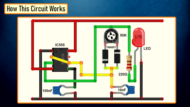 Based on the charging and discharging timings of the Capacitor, a PWM Signal is generated at PIN 3 (OUT PIN) of the 555 Timer IC. The output is then sent to the LED to produce the dimming effect.
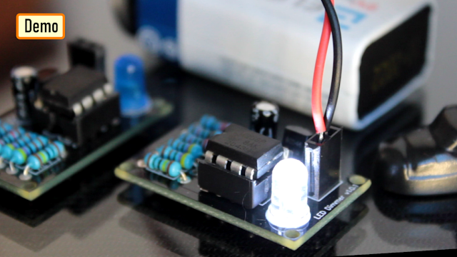
Demo
 So, this is how it looks like.By rotating the knob of the 10K Pot we can adjust the brightness of the connected LED.
With Arduino
 Now, lets repeat these setups using an Arduino. The beauty of Arduino is that it has 6 digital pins that can be used as PWM outputs (3, 5, 6, 9, 10, and 11). PWM signals are sent using the analogWrite() function by passing a value between 0 - 255.- analogWrite(255) requests a 100% duty cycle (always on),- and analogWrite(127) is a 50% duty cycle (on half the time), and so on.
Components Required
For this setup we need:- Arduino UNO/Nano whatever is handy
- 1 x Breadboard
- 1 x LED
- 1 x 220Ω Resistor
- 1 x 10KΩ Potentiometer

Automatic Fading
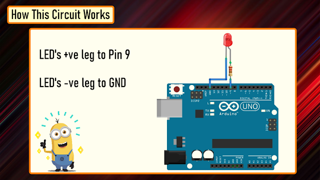 Connect the positive leg of your LED to the digital output PIN9 of your Arduino through a 220Ω resistor. Connect the negative leg directly to the GND. That it, that's how simple it is.
The Code
 After declaring PIN 9 as LedPin, and setting up the pinMode in the setup() section, we are going to loop through and dim the LED in the loop section.By gradually increasing the PWM value from 0 to 255, and then back to 0 we can get the fading effect. In this sketch, the PWM value is set using a variable called 'brightness'. Each time in the loop, it increases by the value of the variable 'fadeAmount'.If brightness is at either extreme of its value (either 0 or 255), then 'fadeAmount' is changed to its negative. So, if the fadeAmount is 5, then it is set to -5 and if it is -5, then it is set to 5. The next time through the loop, this change causes brightness to change its direction. A delay is added to control the speed of the fading effect.
Demo
 So, this is how it looks like.
Manual Fading
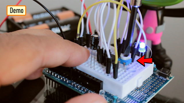
 Connect the positive leg of your LED to the digital output PIN6 of your Arduino through a 220Ω resistor. Connect the negative leg directly to the GND. Connect the left (or right) pin of the 50KΩ PoT to VCC and then connect the right (or left) pin of the PoT to the GND. Now, connect the 'data' pin of your potentiometer to the Analog PIN 'A0' of the Arduino.In this circuit, the potentiometer is working as a voltage divider. One of the outer pins is connected to the GND, the other to Vcc and the middle pin is the voltage output. The wiper position in this setup determines the output voltage.Now, lets have a look at the code.
The Code
 Based on my setup, I set the LedPin as 6 and Potentiometer pin Pot as A0. Another variable 'Knob' is used to read and store the value of the potentiometer.pinMode of the LedPin is set to OUTPUT and we don't need to do anything for the PoT as its default value is already set as input.In the 'loop()' section I am first reading the value of the PoT using the 'analogRead()' function and then mapping its value between 1 to 255. A potentiometer intakes a value between 1 and 1024, but in our setup it has to be between 1 to 255. The 'map()' function divides the value read from the potentiometer into equal intervals of 1/255, which is then sent to the LED using the 'analogWrite()' function.
Demo
 So, this is how it looks like.
Thanks
Thanks again for checking my post. I hope it helps you.If you want to support me subscribe to my YouTube Channel: https://www.youtube.com/user/tarantula3Video: https://youtu.be/IIUsdICycOwGerber File:The Code:1. Automatic Fading : https://drive.google.com/file/d/1hab3sISIlurrPQBat80OLb90RXqQKzLZ/view?usp=sharing2. Manual Fading Using PoT : https://drive.google.com/file/d/1TzXdVO5lVjPNaw_NPSUexIye3WZGJ6cj/view?usp=sharingBTC: 1M1PdxVxSTPLoMK91XnvEPksVuAa4J4dDpLTC: MQFkVkWimYngMwp5SMuSbMP4ADStjysstmDOGE: DDe7Fws24zf7acZevoT8uERnmisiHwR5stETH: 0x939aa4e13ecb4b46663c8017986abc0d204cde60BAT: 0x939aa4e13ecb4b46663c8017986abc0d204cde60LBC: bZ8ANEJFsd2MNFfpoxBhtFNPboh7PmD7M2Thanks, ca again in my next tutorial. -
A Chaser Circuit consists of a clocked IC or other electronic unit like an Arduino that drives an array of LEDs in such a way that individual LEDs (or small groups of LEDs) turn on and off in a predetermined and repeating sequence, thus producing a visually attractive display in which one or more ripples of light seem to repeatedly run through a chain or around a ring of LEDs.In this tutorial I am going to create 3 chaser circuits using Arduino and IC4017 decade counter.
Sponsors
PCBWay specialize in manufacturing of very high quality, low-volume, colored PCBs at a very budgetary price. In addition to the standard PCBs, you can also order Advanced PCBs, Aluminum PCBs, FPC/Rigid-flex PCBs. They also provide PCB assembly and other related service which can meet your needs to the greatest extent.The ordering process from PCBWay is very easy. Once I had my design ready, I just had to upload the gerber file to the PCBWay's website and select the type, color and any other customization that I want and then just send it for fabrication.For my project, I choose the black color. PCBWay ships from china to most of the countries of the world within 3 to 7 business days. Talking about the quality, its absolutely mind-blowing.Using IC555 and IC4017
Lets first create the chaser circuit using the IC4017 decade counter and IC555 timer IC.Components Required

- For the Non-Arduino bit we need:
- 2 x 4017 Decade Counter IC
- 1 x 555 Timer IC
- 1 x 10 K Potentiometer
- 1 x 1 Kilo Ohm Resistor
- 1 x 100 Ohm Resistor
- 1 x 100 MFD Capacitor
- 20 x Zener Diodes and
- 10 x Red LEDs
Circuit Diagram
1. Forward Chaser
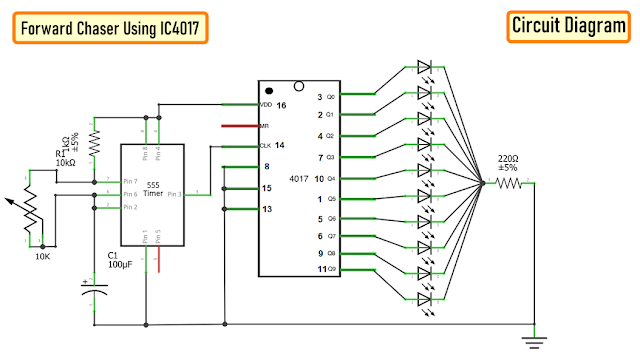 The circuit is very simple.The 555 Timer IC operates as a clock oscillator or clock generator. The output on PIN-3 goes high causing a shift.The signal from the 555 IC clocks the 4017 decade counter. Output of 555 timer IC on PIN-3 is given as an input to 4017 IC through PIN-14. Whenever a pulse is received at the input of IC 4017, the counter increments the count and activates the corresponding output PIN. This IC can count upto 10, so we have attached 10 LEDs to the circuit.By increasing or decreasing the value of resistance of the 10K pot we can adjust the speed of the chaser circuit.Since only one LED will be turned on at a given time, I have attached just one 220ohm current limiting resistor to the cluster of LEDs.Demo: So this is how it looks like.
2. Forward Reverse Chaser using 2 x IC4017
Now, to give the forward and reverse effect we are attaching another 4017 IC to this circuit. If lets say the 1st IC connects from 1 to 10 (left to right) then the second one should connect from 10 to 1 (right to left). However, now we cannot connect the counter ICs directly to the LEDs as we did before. We have to use Diodes to stop the reverse flow of current to the 2nd IC.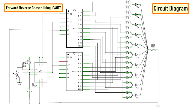 We have also lowered the value of the current limiting resistor to 100ohms as at a given time 2 LEDs will be on, one running from left and one from the right hand side.
 Demo: Now lets do a quick test. By lowering the speed I can get the desired forward and reverse effect. By removing one of the 4017 ICs we can get the effect that I demonstrated in the previous example.
3. Forward Reverse Chaser using 1 x IC4017
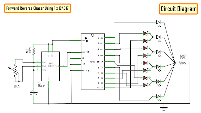 To get a forward reverse effect using one 4017 IC we need to connect 8 diodes to the circuit. The 1st and the 6th LED will be directly connected to the IC4017. The LEDs at the far end will get signals from only one pin however the one in the middle will receive signals from 2 x pins and hence we need diodes to stop the reverse flow of the current.Demo: So this is how it looks like.
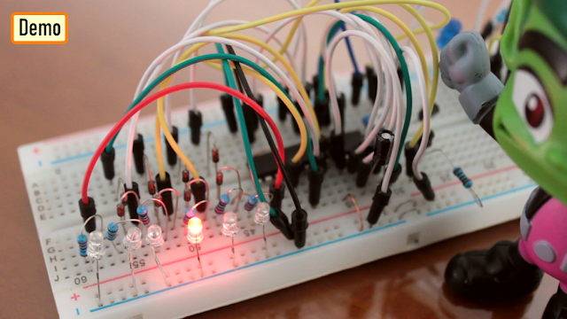
Using Arduino
Now, I am going to repeat the same setup using an Arduino.Components Required

- For the Arduino bit we need:
- 1 x Arduino Uno/Nano (whatever is handy)
- 1 x 220 Ohm Resistor
- 10 x Red LEDs
- Few Connecting Cables
The beauty of using an Arduino is that the setup remains the same for all the previously shown circuits, the only thing that changes is the code. So, I am going to use this simple setup for the rest of the tutorial.Circuit Diagram
1. Forward Chaser

Code: The code for the forward chaser is very simple. Start by defining the constants and the global variables that will be used throughout the code.Then in the setup section define the pin modes.Now, in the loop section we are going to start by turning off all the LEDs followed by turning one LED on at a time. A counter is used to tell the loop which LED to turn on in the next cycle. Once the value of the counter reaches 10 (the maximum number of LEDs) the counter resets to 1 and the 1st LED lights up and the cycle continues.Demo: So this is how it looks like.
2. Forward Reverse Chaser

Code: The code is same as the previous setup. The only thing that changes is the function that deals with the LEDs. In this setup we cycle through LED 1 to LED 10 and then reverse from LED 9 to LED 1. The counter resets when the max count is reached.Demo: So this is how it looks like.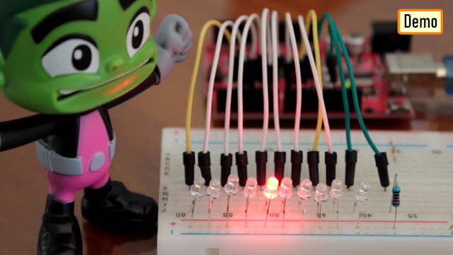
3. Left-Right Chaser
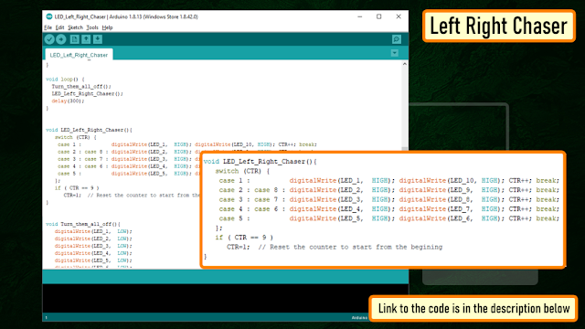
Code: The setup is exactly the same as the previous two setups. This function is the one which turns on the LEDs at the two far ends and then the one before that and likewise until they cross each other. The counter is reset when the max count is reached.Demo: So this is how it looks like.
PCF8574 8-bit GPIO Port Extender
 Using a PCF8574 8-bit GPIO Port Extender we can add even more LEDs to this setup.PCF8574 becomes a life saver when you run out of pins on your Arduino. This "GPIO (General Purpose Input Output) pin extender" provides an additional 8 pins (P0 ~ P7) which can be used to 'output a signal' or 'read a signal as an input'.These modules run on the I2C bus, and if daisy-chained you can connect upto 8 of these devices in a project. Each device will give us an additional 8-bits of GPIO enabling 64 GPIOs in total.To know more about this IC please check out my tutorial number 10 : "PCF8574 GPIO Extender - With Arduino and NodeMCU".
Thanks
Full Blog Post: https://diy-projects4u.blogspot.com/2021/01/led-chaser-circuits-using-ic4017-and.htmlVideo: https://youtu.be/F6V1AjESWbUGerber File:Code:2. Forward Reverse: https://drive.google.com/file/d/1Oag8kxbvfxZg7StFrYzWwtcqQx6okwzd/view?usp=sharing3. Left Right:https://drive.google.com/file/d/17ZEsKU3OFrcjaJpvyUJMQbHQ-lznbp0H/view?usp=sharingSketch:2. Without Arduino: https://drive.google.com/file/d/1LdxcS1BXf3GtQTRhWCoCZKm6ppRwsc5k/view?usp=sharing- BTC: 1M1PdxVxSTPLoMK91XnvEPksVuAa4J4dDp
- DOGE: DDe7Fws24zf7acZevoT8uERnmisiHwR5st
- LTC: LedWPdTaUzr5iaJx8garkcykSs1DZU1FAx
- ETH: 0xB62a901Ee6cE24f3153CA6ae565C2A6533066faA
- BAT: 0xB62a901Ee6cE24f3153CA6ae565C2A6533066faA
- BCH: 14xJhpswSAQi375S39yDFsrBFtDoiLVX1J
-
Trying to explain dialup to a pre-teen will evoke the same wild-eyed bewilderment as “a dinosaur was as-big-as this house”. We can’t go off what our parents did because two tin cans connected by a string isn’t really the same these days and probably it would look like a piece of junk for the new and upcoming generations.However, the truth is "life is busy" and hence we don’t spend enough time with our children. Children need high-quality time with parents and caregivers - the QUALITY of time spent with them is much more important than the QUANTITY of time.Christmas was the perfect time to explore and setup this bonding. With a bit of help from my little monster and by using The Most Complete Starter Kit from ELEGOO I created this small Christmas Village for my little monster.
Components Used [Village Creation]
----------------------------------------------- To create the cardboard village we need:
- Cardboard Sheets
- A4 Paper
- Permanent Marker or Pen
- Scissor and a Knife
- Hot Glue Gun or Wood Glue
Adding a bit color would have made my project even more attractive however I just left it all in white.Paper Templates
--------------------- I created 2 x PDF files with all the measurements in it. The links to the PDF files is in the description below. After printing the PDFs on A4 sheet, I extracted the shapes from it using a paper cutting scissor.
Cutting The Cardboard
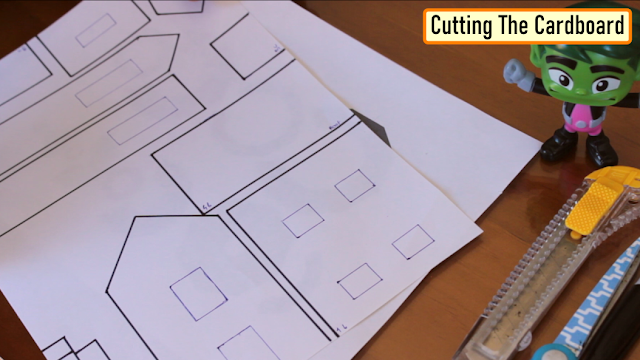
-------------------------------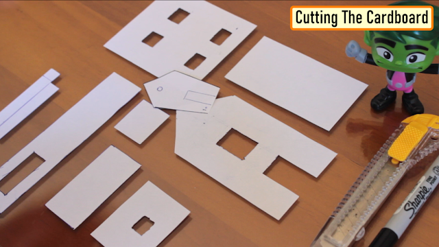 Then I traced the paper-cutouts on pieces of cardboard and using both scissor and knife I extracted all the pieces of cardboard that I need for this project.
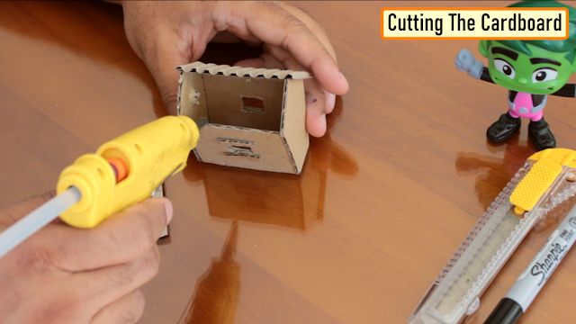 Using a hot-glue gun I joined all the cardboard cutouts.Be very careful while using a hot-glue gun. Use gloves as much as possible to avoid the hot glue from burning your hand and fingers.
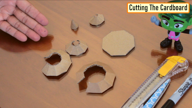 By using wood-glue instead of hot-glue you can get a cleaner and stronger finish, but hot glue is faster. Hot glue can also be more forgiving as you can re-heat and re-glue if you're unsatisfied with your seam.Try applying the glue from the inner side as much as possible to leave the outer side neat and clean.
 Meaningful connections are all about quality of time and not quantity of time. Keep it simple and connect with your child in ways that make sense for your lifestyle and relationship. Each connection has a lasting impact and provides the support and reassurance that your child needs. Although the days with little kids often seem long; however, the years fly-by. Use this practical and purposeful blueprint to enjoy the moments you have together.
Color or Not To Color
---------------------------- So, this is how it looks like. As advised earlier, adding a bit color would have made my project even more attractive however I just left it all in white.I created this wooden frame on which the village will sit. This frame will also house the electronic components inside it.
Components Used [Electronics]
---------------------------------------- Now for the Electronics bit we need the "The Most Complete Starter Kit from ELEGOO".This kit has all the components that are required for this project.
- 1 x ELEGOO UNO R3
- 9 x Blue LEDs
- 9 x White LEDs
- 5 x Yellow LEDs
- 1 x RGB LED
- 3 x 220 Ohm Resistor
- 1 x Stepper Motor
- 1 x Stepper Motor Driver
- 1 x LDR
Adding LEDs
----------------- Using the soldering iron I made few holes around the pathway. These holes are for the Blue and White LEDs which will blink alternately. Adding RGB-LEDs would have definitely given this a better look and feel.Next, I added a RGB-LED to the water-feature. Later, I will add a bit of cotton on top of this which may look like flowing water.
SUN & MOON
------------------- So, this is how the final setup looks like. I added some hills at the back for the rising and setting of the sun and the moon.The logic is very simple.A DC-Motor or Stepper-Motor rotates the Half Sun and Half Moon. A LDR is placed in a way that the Sun rays can cover it up.
 When the moon side is up the sun rays cove the LDR and vice-versa. This LDR acts as a switch and turns on and off the blue and white flashing LEDs. With the same logic you can go even more creative than what I did.
Coding
---------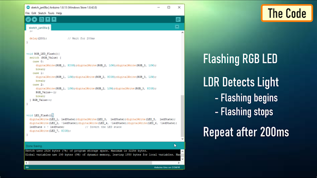 The DC Motor run off the 5V pin of the Arduino so we don't need to code anything for that.For the rest of the code I am looping through and flashing the RGB LEDs followed by checking if the LDR has detected any light and then waiting for 200ms before repeating the process again.
Thanks
----------Thanks again for checking my post. I hope it helps you.If you want to support me subscribe to my YouTube Channel: https://www.youtube.com/user/tarantula3Cardboard Templates:BTC: 35ciN1Z49Y1bReX2U7Etd9hGPWzzzk8TzFDOGE: DDe7Fws24zf7acZevoT8uERnmisiHwR5stLTC: MQFkVkWimYngMwp5SMuSbMP4ADStjysstmETH: 0x939aa4e13ecb4b46663c8017986abc0d204cde60BAT: 0x939aa4e13ecb4b46663c8017986abc0d204cde60Thanks, ca again in my next tutorial. -
Tutorial - Reed switch
Reed switch was invented in 1936 by Walter B. Ellwood in the Bell Telephone Labs. Reed Switch consists of a pair of ferromagnetic (something as easy to magnetize as iron) flexible metal contacts typically nickel-iron alloy (as they are easy to magnetize and doesn't stay magnetized for long) separated by only a few microns, coated with a hard-wearing metal such as Rhodium or Ruthenium(Rh, Ru, Ir, or W) (to give them a long life as they switch on and off) in a hermetically sealed (airtight) glass envelope (to keep them dust and dirt free). The glass tube contains an inert gas (An inert gas is a gas that does not undergo chemical reactions under a set of given conditions) typically Nitrogen or in the case of high voltage it is just a simple vacuum.
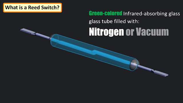
In production, a metal reed is inserted in each end of a glass tube and the end of the tube heated so that it seals around a shank portion on the reed. Green-colored Infrared-absorbing glass is frequently used, so an infrared heat source can concentrate the heat in the small sealing zone of the glass tube. The glass used is of a high electrical resistance and does not contain volatile components such as lead oxide and fluorides which can contaminate the contacts during the sealing operation. The leads of the switch must be handled carefully to prevent breaking the glass envelope.

When a magnet is brought in close proximity to the contacts, an electro-mechanical force field is generated and the stiff nickle iron blades become magnetically polarized and gets attracted to each other, completing the circuit. When the magnet is removed the switch returns to its open state.
Since the contacts of the Reed Switch are sealed away from the atmosphere, they are protected against atmospheric corrosion. The hermetic sealing of a reed switch makes them suitable for use in explosive atmospheres where tiny sparks from conventional switches would constitute a hazard.
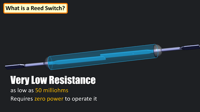
A Reed Switch has very low resistance when closed, typically as low as 50 milliohms hence a Reed Switch can be said to require zero power to operate it.
Components
------------------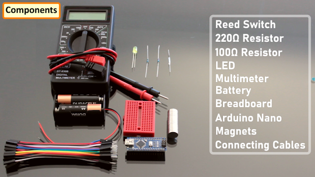
For this tutorial we need:
- Reed Switch
- 220Ω Resistor
- 100Ω Resistor
- LED
- Multi-meter
- Battery
- Breadboard
- Arduino Nano
- Magnets and
- Few Connecting Cables
Demo
--------

Using a multi-meter I am going to show you how a Reed Switch works. When I bring a magnet close to the switch the multi-meter shows a continuity as the contact touches each other to completing the circuit. When the magnet is removed, the switch returns to its normally open state.
Types of Reed Switches
----------------------------------
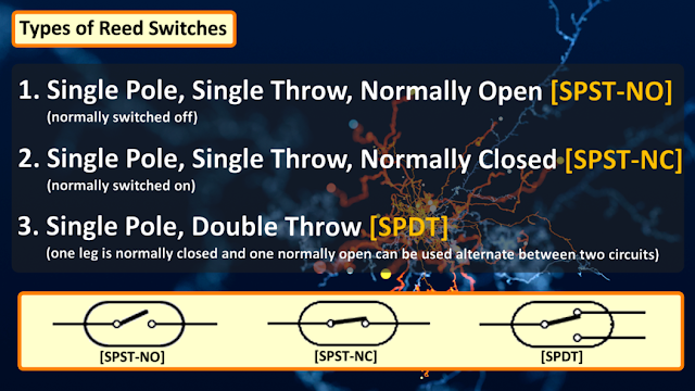
There are 3 basic types of Reed Switches:
1. Single Pole, Single Throw, Normally Open [SPST-NO] (normally switched off)
2. Single Pole, Single Throw, Normally Closed [SPST-NC] (normally switched on)
3. Single Pole, Double Throw [SPDT] (one leg is normally closed and one normally open can be used alternate between two circuits)
Although most reed switches have two ferromagnetic contacts, some have one contact that's ferromagnetic and one that's non-magnetic, while some like the original Elwood reed switch have three. They also vary in shapes and sizes.
Connecting Without Arduino
-----------------------------------------
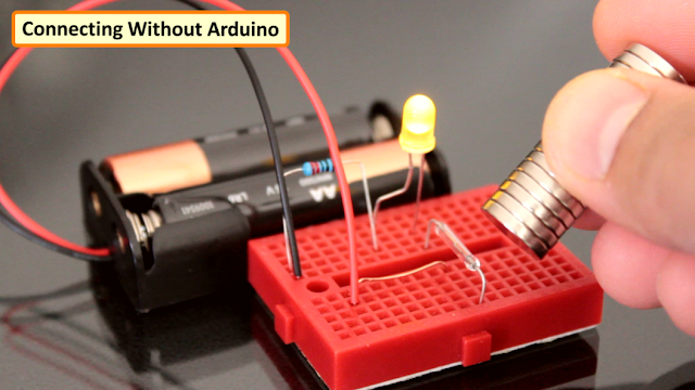
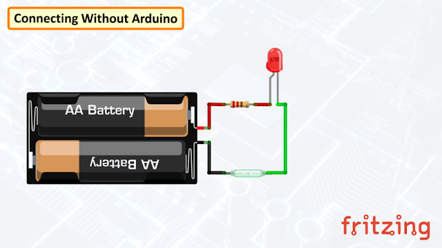
Lets first test the Reed Switch without an Arduino. Connect a LED in series with the Reed Switch to a battery. When a magnet is brought in close proximity to the contacts, the LED lights up when the nickle-iron blades inside the switch attracts each other, completing the circuit. And, when the magnet is removed the switch returns to its open state and the LED turns off.
Connecting Reed Switch to Arduino
---------------------------------------------------

Now, lets connect the Reed Switch to an Arduino. Connect the LED to the pin 12 of the Arduino. Then connect the Reed Switch to the pin number 13 and ground the other end. We also need a 100ohm pull-up resistor connected to the same pin to allow a controlled flow of current to the digital input pin. If you want, you can also use the internal pull-up resistor of the Arduino for this setup.
The code is very simple. Set the pin number 13 as Reed_PIN and pin number 12 as LED_PIN. In the setup section, set the pin-mode of the Reed_PIN as input and LED_PIN as output. And Finally in the loop section, turn on the LED when the Reed_PIN goes low.

Same as before, when a magnet is brought in close proximity to the contacts, the LED lights up and, when the magnet is removed the switch returns to its open state and the LED turns off.
Reed Relay
----------------
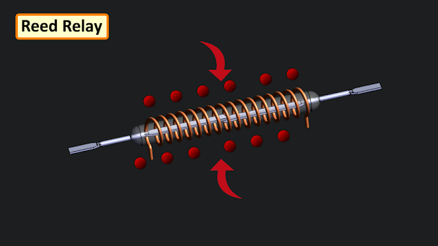
Another widespread use of Reed Switch is in the manufacturing of Reed Relays.
In a Reed Relay the magnetic field is generated by an electrical current flowing through an operating coil which is fitted over "one or more" Reed Switchs. The current flowing in the coil operates the Reed Switch. These coils often have many thousands of turns of very fine wire. When the operating voltage is applied to the coil a magnetic field is generated which in turn closed the switch in the same way the permanent magnet does.
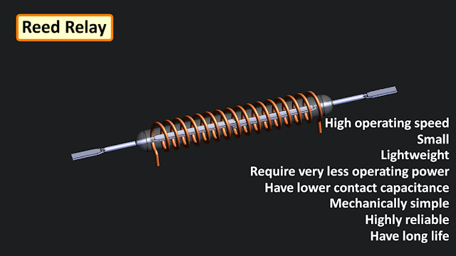
Compared to armature-based relays, Reed Relays can switch much faster, as the moving parts are small and lightweight (although switch bounce is still present). They require very less operating power and have lower contact capacitance. Their current handling capacity is limited but, with appropriate contact materials, they are suitable for "dry" switching applications. They are mechanically simple, offer high operating speed, good performance with very small currents, highly reliable and have long life.
Millions of reed relays were used in telephone exchanges in the year 1970s and 1980s.
Areas of Application
-----------------------------
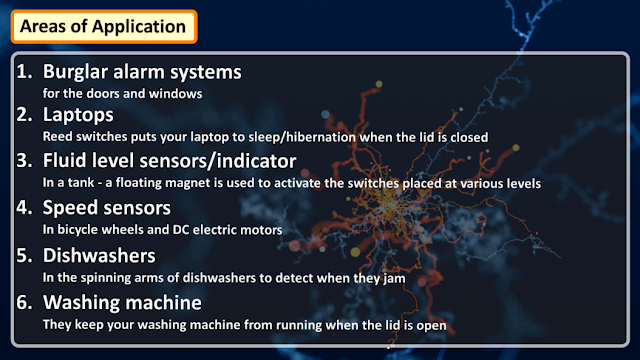
Just about everywhere you go, you'll find a Reed Switch nearby that’s quietly doing its job. Reed switches are so pervasive that you’re probably never more than a few feet away from one at any given time. Some of their areas of application are in:
1. Burglar alarm systems for the doors and windows.
2. Reed switches puts your laptop to sleep/hibernation when the lid is closed
3. Fluid level sensors/indicator in a tank - a floating magnet is used to activate the switches placed at various levels.
4. Speed sensors on bicycle wheels/ DC electric motors
5. In the spinning arms of dishwashers to detect when they jam
6. They keep your washing machine from running when the lid is open
7. In the thermal cut-offs in electric showers, to stop the water heating to dangerous levels.
8. They know if the car has enough brake fluid and whether or not your seat belt is fastened.
9. Anemometers with rotating cups have reed switches inside that measure the speed of the wind.
10. They are also used in applications which make use of their extremely low leakage of current.
11. Old keyboards, in vehicles, industrial systems, Household appliances, telecommunication, medical appliances, Clamshell phones and more......
On the relays side they are used for automatic cut sequences.
Life
-----

The mechanical motion of the reeds is below the fatigue limit of the materials, so the reeds do not break due to fatigue. Wear and life are almost entirely dependent on the electrical load's effect on the contacts along with the material of the reed switch. Contact surface wear occurs only when the switch contacts open or close. Because of this, manufacturers rate life in number of operations rather than hours or years. In general, higher voltages and higher currents cause faster wear and shorter life.
The glass envelope extended their life and can be damaged if the reed switch is subjected to mechanical stress. They’re cheap, they’re durable, and in low-current applications, depending on the electrical load, they can last for about a billion actuation.
Thanks
----------
Thanks again for checking my post. I hope it helps you.
If you want to support me subscribe to my YouTube Channel: https://www.youtube.com/user/tarantula3
Full Blog Post: https://diy-projects4u.blogspot.com/2020/07/reed-switch.html
Video: https://youtu.be/WA1tp-f81p8
Support my work:
BTC: 35ciN1Z49Y1bReX2U7Etd9hGPWzzzk8TzF
LTC: MQFkVkWimYngMwp5SMuSbMP4ADStjysstm
ETH: 0x939aa4e13ecb4b46663c8017986abc0d204cde60
DOGE: DDe7Fws24zf7acZevoT8uERnmisiHwR5st
TRX: TQJRvEfKc7NibQsuA9nuJhh9irV1CyRmnW
BAT: 0x939aa4e13ecb4b46663c8017986abc0d204cde60
BCH: qrfevmdvmwufpdvh0vpx072z35et2eyefv3fa9fc3z
#ReedSwitch #ReedRelay #Arduino -
The very first program you write when you start learning anew programming language is: "Hello World!".The program itself does nothing more than printing a “Hello World” text on the screen.So, how do we get our Arduino to display the "Hello World!"?In this video, I will be showing you how to get started with the small 0.91 (128x32) and 0.96 (128x64) I2C OLED displays.There are 100s of tutorials on the web explaining the same thing in different ways, but I couldn't find one that tells me all about the OLED display and how to use it in different scenarios. It took me some time to work it all out. So, I thought I should create a tutorial on what I have learned and combine all the features and ways the OLED displays can be used in our projects.
Step 1: Things We Are Going to Learn Today
 In this video we will be talking about:- What is an OLED display?- Then we will have a closer look at the 0.91 (128x32) and 0.96 (128x64) I2C OLED displays- Next we will talk about installing the Adafruit Library to your Arduino IDE- Then we will connect NodeMCU and Arduino to an OLED display- Next we will have a look at the code and display some graphics and text on it- We will also talk about applying Custom Fonts and displaying Images- Then we will connect Multiple OLEDs to a micro-controller using I2C Multiplexer- Finally, we will talk about few common errors people make while using the OLED displays
Step 2: Hardware Requirement
 For this tutorial we need:- A Breadboard- A 0.91" (128x32) and 0.96" (128x64) I2C OLED displays- Arduino UNO/NANO (whatever is handy)- NodeMCU- TCA9548A I2C multiplexer- Few Connecting Cables- and a USB cable to upload the code
Step 3: What Is an OLED Display?

 OLED or organic light-emitting diode is a light-emittingdiode (LED) in which the emissive electroluminescent layer is a film of organic compound (millions of small LED lights) that emits light in response to an electric current.OLEDs are used to create digital displays in devices such as television screens, computer monitors, portable systems such as mobile phones, hand-held game consoles and PDAs. An OLED display works without a backlight because it emits visible light.
 There are many types of OLED displays available in themarket based on their- Sizes- Color- Brands- Protocol- SPI (Serial Peripheral Interface) or I2C- Passive-matrix (PMOLED) or active-matrix (AMOLED) control schemeIn this tutorial, I am going to talk about connecting theblue color 0.91 (128x32 OLED) and 0.96 (128x64 OLED) I2C OLDE displays to an Arduino NANO and NodeMCU. I2C bus technology uses only 2 pins of the MCU so we have heaps available for other sensors.
Step 4: Closer Look


 Lets have a closer at these two displays.At the back of these displays there are heaps of SMD capacitors and resistors soldered on-board; but, since its an I2C device we only care about these 2 pins (SCL and SDA)The display connects to Arduino using only four wires – two for power (VCC and GND) and two for data (serial clock SCL andserial data SDA), making the wiring very simple. The data connection is I2C (I²C, IIC or Inter-Integrated Circuit) and this interface is also called TWI (Two Wire Interface).- The on-board pins can be in different order, so always triple check before hooking it up to your project.- Operation voltage is between 3v to 5v but, it is best to use the guidance from the manufacturer's datasheet.- Sometimes we need to use 2 displays in our projects. So, how can we achieve this?The trick is to have a configurable address on your display. This unit has a configurable address between 0x78 and 0x7A. Just by unsoldering the 0Ohm resistor from one side and hoking it up to the other side or just by putting a global solder we can change the address. We will talk about it in depth when we hook up multiple displays to an Arduino in the later section of this tutorial.In picture these displays look very big. But, practically speaking they are tiny. They are made of 128 x 32/64 individual OLED pixels and do not require any back-light. Just have a look at this and see how small it is. Even though they are small they can be very useful in any electronic projects.
Step 5: Library


 There are several libraries available to control thesedisplays. In past I have used the "u8glib library" but I find the AdaFruit library very easy to understand and use in our projects. So, I am going to use the AdaFruit library in this tutorial.To control the OLED display you’ll need the "adafruit_GFX.h" library and the "adafruit_SSD1306.h" library.There are two ways you can download and install the library to your Arduino IDE.Method 1Go to the "Library manager" and search "adafruit_SSD1306" and "adafruit_gfx"Select the latest version and hit the Install button.Once installed you can use these libraries in your program.Method 2These two libraries can be also be downloaded from github (you need both):I will provide the links in the description below.The display library: https://github.com/adafruit/Adafruit_SSD1306The GFX library: https://github.com/adafruit/Adafruit-GFX-LibraryOnce downloaded, copy the Adafruit_SSD1306-master folder from the downloaded zipped file into the Arduino libraries folder. This folder is usually found at Documents > Arduino > libraries on Windows systems. On Linux it is usually found at home folder > Arduino > libraries. Finally in the Arduino library folder, rename the Adafruit_SSD1306-master folder to Adafruit_SSD1306. Even if you don’t rename that’s fine.
 Now, lets have a look at the "Adafruit_SSD1306.h"fileTwo things we need to know in this library:1. If you want to use the smaller display use the default 128_32 otherwise for the bigger display comment the 128_32 and uncomment the 128_642. If you have soldered the 0x7A Address on the board (which we will talk about later) then use the 7 bit 0x3D address for the bigger displays, otherwise use the default 0x3C address. For the smaller displays the address is 0x3C.
Step 6: Wiring 128 X 64/32 OLEDs
 Lets start by connecting the NodeMCU to the display.The first and most important thing to note is that some of the displays may have the GND and VCC power pins swapped around. Check your display to make sure that it is the same as the image. If the pins are swapped, make sure to change the connections to the Arduino or NodeMCU.- NodeMCU OLED WiringOLED VCC – NodeMCU 3.3VOLED GND – NodeMCU GNDOLED SCL – NodeMCU D1OLED SDA – NodeMCU D2- Arduino Uno OLED WiringOLED VCC – Arduino 5VOLED GND – Arduino GNDOLED SCL – Arduino Uno A5OLED SDA – Arduino Uno A4- Arduino MEGA 2560 OLED WiringOLED VCC – Arduino 5VOLED GND – Arduino GNDOLED SCL – Arduino MEGA 2560 pin 21OLED SDA – Arduino MEGA 2560 pin 20
Step 7: Code


 Adafruit library comes with really good examples for both128x32 and 128x64 displays.The Library is located under File > Examples > Adafruit SSD1306 > and then the display type in the Arduino IDE.We are going to use the 128x32 I2C example and will modify it to work with both 128x64 and 128x32 displays fist by hooking it up to an Arduino and then to a NodeMCU board.The code starts by including both the Adafruit libraries. In this tutorial I am going to stress on only those parts of the code which are necessary for us to load on both boards and displays. If you want to know more about the code please drop a comment on my blog or in the comments section below and I endeavour to get back to you.- First we are going to load the code to an Arduino Nano connected to a 128x32 display.We can use the code as is without any modifications.128x32 uses 0x3C address so this bit looks all good here, lets double check the header library, yes its also using the 0x3C address and the display type is 128x32.- Now lets connect the 128x64 display. As we know it uses the 0x3C address by default so we don't need to update the address in either the code or the library.We just need we need to comment the 128_32 and uncomment the 128_64 in the header library and change the LCDHEIGHT to 64 in our code.- Now to run the same code on a NodeMCU we need to change one more line in our code.The "#define OLED_RESET 4" > "#define OLED_RESET LED_BUILTIN" rest of the code is same as ArduinoPretty much to display anything we first need to clear the previous screen usingdisplay.clearDisplay(); // Clear the bufferThen draw the objecttestdrawline(); // Draw a lineShow it on the hardwaredisplay.display(); // Make them visible on the display hardware!Wait for some time before displaying the next item.delay(2000); // Wait for 2 secondsIn this example we are displaying few items like text, lines, circles, scrolling text, triangles and more. Go ahead and use your imagination and display whatever you want on these tiny displays.Attachments
Step 8: Customizing Text & Adding Images


 Sometimes your code needs to display custom fonts andimages. If you are very good in bit mapping then you just need to create a byte arrays by turning on or off the tiny LEDs of the display to create custom fonts and images.However, I am not very good in doing these mappings and don't want to spend hours creating the bit map tables.So, what are my options? I generally use two websites to generate custom fonts and images. The links are provided in the description below.Custom Fonts------------Go to the font converter website, select the font family, style, size, Library Version as "Adafruit GFX Font" and then hit the "Create" button. On the right hand side of this page you can see how your font is going to look like on the actual display.Based on your selection the webpage generates the fonts header file. Create a file called "modified_font.h" in the same folder where your code is and copy and save the generated code into it. Then you just need to include the header file in your code to use the custom font.#include "modified_font.h"Then, you just need to set the font before displaying the text to apply the custom font to it.display.setFont(&Your_Fonts_Name);You can get the name of the font from the header file you just added to your project. Thats it, easy.Memory is always a concern while using custom fonts, so always consider the bytes that will be consumed by the memory. Just remember Arduino UNO has only 32K of memory.Custom Images-------------To display a bitmap image on your screen you first need to create a 128 x 64/32 sized image.I am using the good old "MS Paint" to create a 128 x 64 bitmap image which I will then upload to this image converter website. The website converts images into byte-strings, which can be used with Arduino and OLED displays.Start by uploading the image to the website. Then put a check on the "Invert image colors" check-box and change the "Output code format" to "Arduino Code" next select the orientation and hit the "Generate Code" button to generate the byte array. The "Preview" section shows you how your image will look like on the actual display.I have included the code along with this tutorial which you can use to display your images. You just need to replace the array in my code with the one you just generated and then load it to your Arduino.
Attachments
Step 9: Connecting 2 Displays

 Connecting two 128 x 64 displays to your project is easy.You just need to unsolder the 0Ohm resistor from 0x78 address and put it on 0x7A and then use the 0x3D address in your code instead of the default 0x3C.You must be wondering why we are using the 0x3C and 0x3D address and not the actual 0x78 and 0x7A. Arduino accepts 7-bit address and not the 8-bit hardware addresses. So, we first need to convert the 8-bit address to binary, and then chop off the least significant bit to get the 7 bits. Then convert the 7 bits to HEX to get the 0x3C or 0x3D addresses which you enter in your code.First, initialize the display by giving it a unique name:Adafruit_SSD1306 display1(OLED_REST);Adafruit_SSD1306 display2(OLED_REST);Then in your code use the display 1 and display 2 to call the begin statements with the device addresses in them:display1.begin(SSD1306_SWITCHCAPVCC, 0x3C); // display 1 op address 0x3Cdisplay2.begin(SSD1306_SWITCHCAPVCC, 0x3D); // display 2 op address 0x3DThat's it, you can now go ahead and do whatever you want using either Display 1 or Display 2 in the rest of your code. I have provided an example with this tutorial.Wiring is exactly the same as what we have done before, pretty much you just need to add another display to the same I2C pins of either the Arduino or NodeMCU. Based on the addresses, the MCU then sends the data on the I2C data line.
Attachments
Step 10: Connecting More Than 2 Displays


 3 More ImagesNow, what if you want to hook up more than 2 displays?Arduino has limited number of pins and hence you cannot have more than a certain amount of shields attached to it. Moreover, it has only one pair of I2C buses.So, how can we attach more than 2 I2C displays to an Arduino? The trick is to use a TCA9548 Multiplexer.TCA9548 allows a single micro-controller to communicate with up to '64 sensors' all with the same or different I2C address by assigning a unique channel to each sensor slave sub-bus.When we talk about sending data over 2 wires to multiple devices we then need a way to address them. Its same as the postman coming on a single road and dropping the mail packets to different houses because they have different addresses written on them.The Multiplexer connects to 3V3, GND, SDA and SCL lines of the micro-controller. The slave sensors are connected to one of eight SCL/SDA slave ports on the board. The channels are selected by sending the TCA9548A its I2C address (0x70 {default} - 0x77) followed by the channel number (0b00000001 - 0b10000000). You could have at the max 8 of these multiplexers connected together on 0x70-0x77 addresses in order to control 64 of the same I2C addressed parts. By connecting the three address bits A0, A1 and A2 to VIN you can get different combination of the addresses. I will explain this in-depth in my next tutorial on TCA9548A breakout board. For now, lets just hook up 8 OLEDs to this board and have a quick look at the code.Connection:VIN to 5V (or 3.3V)GND to groundSCL to I2C clockSDA to I2C dataThen wire up the sensors to VIN, GND and use one of the SCn / SDn multiplexed busesNow, Int the code lets start by including the "Wire" library and by defining the multiplexers address.#include "Wire.h"#include#define MUX_Address 0x70 // TCA9548A Encoders addressThen we need to select the port we want to communicate to and send the data on it using this function:void tcaselect(uint8_t i) {if (i > 7) return;Wire.beginTransmission(MUX_Address);Wire.write(1 << i);Wire.endTransmission();}Next we will initialize the display in the setup section by calling "u8g.begin();" for each display attached to the MUX "tcaselect(i);"Once initialized, we can then do whatever we want just by calling the function "tcaselect(i);" where "i" is the value of the multiplexed bus and then sending the data and clock accordingly.
Attachments
Step 11: Advantages and Disadvantages
 The image of an OLED is beautiful. However, OLEDs also havedisadvantages. Because OLED screens contain organic material, their lifespan is shorter than LCD displays. Additionally, many OLED displays get burn-ins after showing the same image for a long time. After a burn-in, the image stays on the screen even after showing another image. So make sure you keep refreshing the screen every few seconds. Water can instantly damage the organic materials of these displays.AdvantagesNo need for a backlightDisplays are very thin and lightweightLow power consumptionViewing angles are wider than LCDsBrightness and contrast are greatHigh speed and have low response timeDeep black colorDisadvantagesCostly technologyShort lifecycleOLEDS are more likely to burn-inWater damage
Step 12: Common Errors
 To conclude the tutorial lets talk about few common errorspeople make while using these displays:- Always triple check the pins before using it in your project- Pick up the right library address in the header file and in your code#define SSD1306_I2C_ADDRESS 0x3C // in Adafruit_SSD1306.handdisplay.begin(SSD1306_SWITCHCAPVCC, 0x3C); // in your codeIf the address is wrong the OLED will not display anything- The display size must be changed in the driver before it can be used. If it is not changed you will get an error message when attempting to verify the code#error ("Height incorrect, please fix Adafruit_SSD1306.h!");- If using NodeMCU make sure you replace the OLED_RESET from 4 to LED_BUILTIN#define OLED_RESET LED_BUILTINI have scene people making all sorts of things using this OLED display. Some have even made video games and all. I am really not interested in making a video game using this tiny display. However, I will now leave you to explore your imaginations and come out with amazing ideas.- Add Image: http://javl.github.io/image2cpp/- Custom Text: http://oleddisplay.squix.ch/#/home- Adafruit display library: https://github.com/adafruit/Adafruit_SSD1306- Adafruit GFX library: https://github.com/adafruit/Adafruit-GFX-Library- u8glib library: https://code.google.com/archive/p/u8glib/ or https://github.com/olikraus/u8glibIf you want to use the smaller display use the default 128_32 otherwise for the bigger display comment the 128_32 and uncomment the 128X64 NO_ACK in your code (just uncomment the type of screen you are using) (fonts are in the fonts library)
Attachments
-
Has this ever happened to you?
You come back from a romantic dinner date and when you open the shutter door of your garage you realize that you left the garage light ON. You spent few hours outside with your partner to impress her and all the time this light bulb was on. You immediately turn around and look at her face to see a silent anger on her face. Alright, enough of that. So, in this tutorial, I am going to turn on and off the garage light using a PIR sensor. When the sensor detects a moving object, it turns on the light bulb and when the moving object is gone, it turns it off. Lastly, I am going to make sure that light bulb only turn on during the night time (when its dark).
Step 1: Logic

In this project, I will be using a PIR sensor along with an LDR to turn on or off a light bulb using a Relay.
The things I need to consider before designing the circuit are:
- The bulb should only turn on when the room is dark and when a motion is detected.
- The bulb should turn off after 30 seconds of the object leaving the sensors proximity.
- Most important, we need to place the LDR in a place where it doesn't turn off the bulb as soon as it lights up.
Step 2: Hardware

For this tutorial we need:
A General Purpose PCB
2 x HC-SR501 PIR Sensor
2 x 1N4148 Small Signal Fast Switching Diodes
1 x 1N4007 High Voltage, High Current Rated Diode to protect the micro-controller from voltage spikes
1 x LDR
1 x 10K Trimmer Potentiometer
2 x 470 Ohms Resistor
1 x 10K Resistor
1 x 1K Resistor
1 x 2N3906 General Purpose PNP Transistor
1 x 2N2222 General Purpose NPN Transistor
1 x 5V Relay
1 x LED to display the status
5 x Terminal Blocks
1 x 220V to 5V Buck Step Down Module
Few Connecting Cables And General Soldering Equipments
Step 3: Assembly

Lets first connect the LDR and setup the light detection bit.
As we all know we need to setup a voltage divider to use the LDR in a circuit, so, I am adding this 10K POT and 470ohms resistor to setup the voltage divider bit. By adjusting the resistance of the POT we can adjust the intensity of sunlight at which this circuit will operate.
Now, lets install the PIR sensor. Connect the VCC to +5v and GND to ground. Then connect the 1N4148 diode to the OUT of the sensor. In this circuit, I am installing just one sensor however in the actual project I have used 2 sensors to capture a bit more than 180 degrees. So, to avoid the sensors from back-feeding each other we need to install a diode to the OUT pin of each sensor. If you want to capture motion at 360 degrees you may need 3 to 4 sensor and diode pair to achieve that.
Now that we have the PIR sensor and the LDR in place we need to add the 'AND' functionality. To achieve this I am adding a general purpose PNP transistor. When a motion is detected 'and' when the sunlight is at a certain intensity (adjusted by the POT) current flows out of the transistor.
Next, we need to amplify the current received from the collector of the PNP transistor and turn on and off the LED indicator and the Relay. A general purpose NPN transistor is used to achieve this. That's it all done.Step 4: What Have I Have Made

So, this is what I have made.
On my board components are pretty much soldered everywhere, but you may like to have them nicely installed to give it a bit more cleaner look. OK, so lets check out how this works.
Step 5: Demo
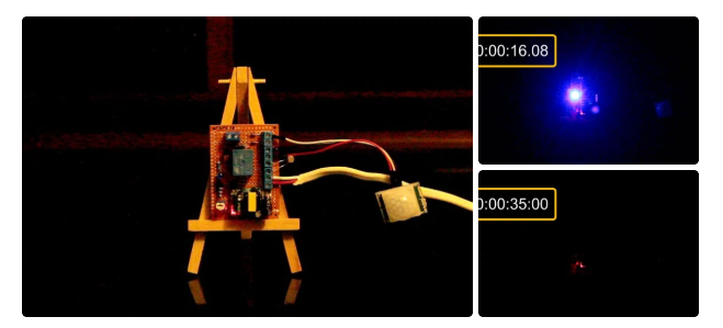
Alright, I have placed the board on this table to do a quick test. I haven't hooked up a light bulb to the circuit yet. However, the LED indicator should serve the purpose of this demonstration.
So, now I am going to turn off the light and make the room dark. Let's see if the sensor picks up motion and lights up the LED. Tada, it works.
Now, lets turn on the light of the room and see if the LED indicator turns off or not. Yessss, that works.
OK, finally just want to make sure that the light bulb turns off after 30 seconds of me moving out of the sensors proximity. Boom, and that concludes the project. I can now install it on the ceiling and make my partner happy.Instead of having 2 to 3 PIR sensors you can use one and install it at the corner of the wall. However, that will require a fair bit of wiring either inside the roof or on the ceiling, which will be way more expensive and tedious than installing 3 sensors an d putting the device in the middle of the room.
You can also swap the Arduino with a NodeMCU board and do a remote data logging to log the time when the sensor detected motion or when the light went on to record when people entered your garage and how long they stayed in there.
Step 6: Areas of Applications of PIR Sensors

This setup can be used to:
* Automate All Outdoor Lights
* Automate Lights of Basement, Garden or Covered Parking Areas
* Automate Lift Lobby or Common Staircases Lights
* Automate bedside or night lamp
* Create a Smart Home Automation & Security System and more..
Step 7: Thanks
Thanks again for watching this video! I hope it helps you. If you want to support me, you can subscribe to my channel and watch my other videos. Thanks, ca again in my next video.
-
Just before creating my next projects tutorial, which will be using a PIR sensor, I thought I might create a separate tutorial explaining the working of a PIR sensor. By doing that I will be able to keep my other tutorial short and to the point. So, without wasting time let’s discuss what is a PIR sensor and how we can use it in our project.
Step 1: Basic
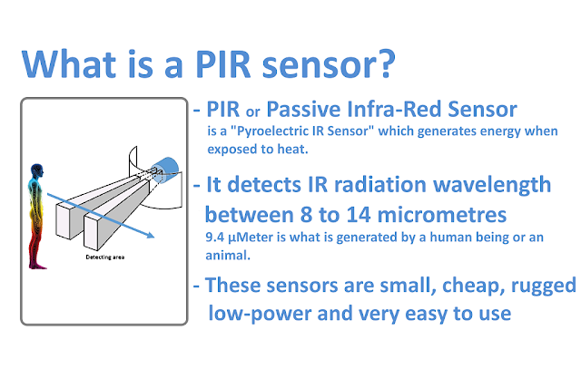 What is a PIR sensor?PIR or "Passive Infra-Red" sensor is a "Pyroelectric IR Sensor" which generates energy when exposed to heat. Everything emits some low level of radiation, the hotter the object is, the more radiation is emitted. When a human or an animal (with IR radiation wavelength of 9.4µMeter) approaches the sensors range the sensor detects the heat in the form of infrared radiation. The sensor only detects the energy emitted by other objects and don't produce any, that's why the sensor is called a PIR or "Passive Infra-Red" sensor. These sensors are small, cheap, rugged, low-power and very easy to use.
Step 2: Hardware
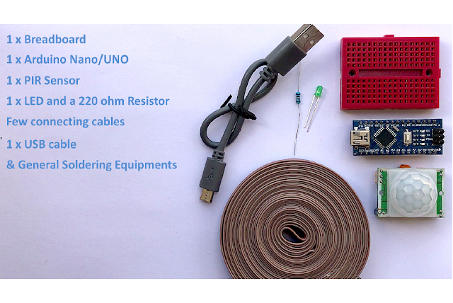
For this tutorial we need:
1 x Breadboard1 x Arduino Nano/UNO (Whatever is handy)1 x PIR Sensor1 x LED and a 220 ohm current limiting resistor to test the connectivityFew connecting cablesA USB cable to upload the code to the Arduino& General Soldering EquipmentsStep 3: Architecture
 As we can see the sensor has two sides:1. Top or the Sensor Side2. Bottom or the Components SideThe Top consist of a specially designed 'High-Density Polythene' cover called "Fresnel Lens". This lens focuses the infrared rays to the underlying 'Pyroelectric Sensor'. 9.4 µMeter infrared rays can easily pass through the polyethylene cover. The sensors sensitivity range between 6 to 7 meters (20 feet) and the detection angle is 110 degrees x 70 degrees. The actual sensor is inside a sealed metal can. The can basically protects the sensor from noise, temperature and humidity. There is a tiny window made of IR-transmissive material to allow the IR signals to reach the sensor. Behind this window are 'two' balanced PIR sensors. In idle state, both sensors detect the same amount of IR radiation. When a warm body passes by, it first intercepts one of the two sensors, causing a positive differential change between the two halves. And then, when it leaves the sensing area, the reverse happens, and the sensor generates a negative differential change. When the pulse changes or in other words the PIR sensor detects motion, the output pin changes to "digital high" or 3.3V.The bottom bit consists of a bunch of circuitry. Few of them are of our interest.- Most PIR sensors have 3-pins VCC, GND and OUT. VCC and GND are to power the module (Operating voltage: DC 5V to 20V). The OUTPUT pin is the one which communicates with the micro-controller by sending digital pulse high (3.3v) when a motion is detected and digital low (0v) when no motion is detected. The pin-outs may vary between modules so always triple-check the pin-outs.- The BISS0001 or the "Micro Power PIR Motion Detector IC" gets the output from the sensor and after doing some minor processing it produces the digital output.- The module has two potentiometers one to adjust the sensitivity (which is up to 7m) and the other to adjust the time for which the output signal should stay high when an object is detected (it ranges from 0.3s to 5 mins).- There are 3 more pins on this module with a jumper between them to select the trigger modes.> 1st one is called "non-repeatable trigger" - this one goes low as soon as the delay time is over.> 2nd one is called "repeatable trigger" - it stays high as long as the object is in the proximity and will turn off once the object is gone and the delay is over. I will be using this mode for this project.If you want to do a quick test before going ahead with this tutorial please follow the steps below.A testing is also a good idea to test the range and duration of sensing.
Step 4: Connecting Without Arduino
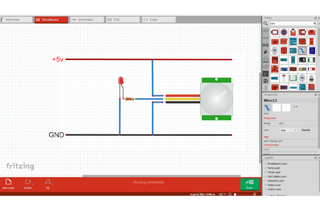 - Connect the VCC to the +5v rail of the breadboard- Connect the GND to the -ve rail- Connect the LED along with a 220 ohm resistor to the OUT pin of the sensorNow, when the sensor detects a motion, the output pin will go "high" and the LED will light up. Move back and forward to find out the sensing the range. Then to test the duration walk in front of the sensor and then walk away and use a stopwatch to find out how long the LED stayed on. You can adjust the time or sensitivity by adjusting the POTs on the board.
Step 5: Connecting With Arduino
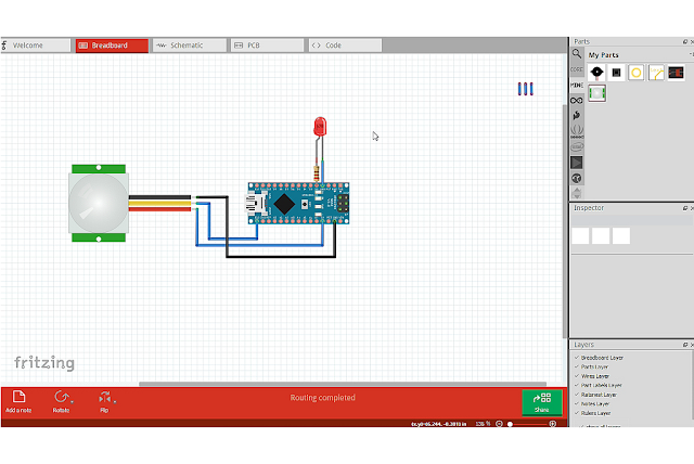 Now, to do the same with Arduino connect the VCC of the PIR sensor to the 5v pin of Arduino.Then connect the OUTput pin to D13 and GND to the Ground pin of the Arduino. Now, connect the LED along with a 220 ohm resistor to the D2 pin of the Arduino. Thats it, now you just need to upload the code and test if everything works the way it should. You can replace the LED with a Buzzer (to raise an alarm when an object is detected) or a Relay to drive a high voltage circuit.To learn more about relays please have a look at my tutorial Number 4 - "Driving a Relay with an Arduino".
Step 6: Code
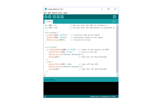 The code is very simple* Start by defining the pin number 2 and 13 as LED pin and PIR pin respectively* Then we need to define the pin modes. LED pin to be the OUTPUT pin and PIR pin to be the INPUT pin* Next we need to read the value of the PIR pin and see if it is HIGH* If the value is HIGH, then turn ON the LED otherwise turn it OFF
Step 7: Areas of Application of PIR Sensors
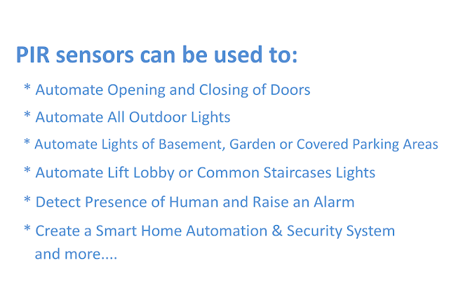 PIR sensors can be used to:* Automate Opening and Closing of Doors* Automate All Outdoor Lights* Automate Lights of Basement, Garden or Covered Parking Areas* Automate Lift Lobby or Common Staircases Lights* Detect Presence of Human and Raise an Alarm* Create a Smart Home Automation & Security System, and many more....
Step 8: Demo
So, this is my setup for the testing of the PIR sensor. The sensor is hooked up to the breadboard and is sitting on the table. As I am in front of the sensor the LED is on.Now, lets do a quick test. Currently, the sensor is in its idle state. I am going to walk in front of the it to activate the sensor. Tada, the LED just turned on after detecting my presence. The light stays on as long as I am in the sensors proximity. OK, lets walk away and start my stop watch to see if it turns off after 5 seconds. Success, everything worked the way I wanted.Thanks again for watching this video! I hope it helps you. If you want to support me, you can subscribe to my channel and watch my other videos. Thanks, ca again in my next video. -
On 3/23/2018 at 4:36 PM, davidjackson said:
Impressive. It is not easy to charge the 150ah battery with solar panel directly. For proper charging using solar panel you just need to use a solar charge controller. You must also place the batteries in parallel connection for fast charge. Using solar charge controller avoid reverse current flow from Battery to a solar panel and unharmed pannels from burning. For proper charging your solar panel must create power more than 150w 150w is the threshold point for your charging. More the power added ……charging rate improve.
-
DRIVING A RELAY WITH AN ARDUINO
Hello everyone, welcome back to my channel. This is my 4th tutorial on how to drive a RELAY (not a relay module) with an Arduino.There are hundreds of tutorial available on how to use a "relay module" but I could not find a good one that shows how to use a Relay and not a Relay module. So, here we are to discuss how a relay works and how we can hook it up to an Arduino.Note: If you do any work with "mains power" such as 120v or 240v AC power wiring, you should always use proper equipments and safety gears and determine whether you have adequate skill and experience or consult a Licensed Electrician. This projects is not intended for use by children.Step 1: Basics
 A Relay is a large mechanical switch, which is toggled on or off by energizing a coil.Depending on the operating principle and structural features relays are of different types, such as:1. Electromagnetic Relays2. Solid State Relays3. Thermal Relays4. Power Varied Relays5. Reed Relays6. Hybrid Relays7. Multi-dimensional Relays and so on, with varied ratings, sizes and applications.However, in this tutorial we will only be discussing about an electromagnetic relays.Guide to Different Types of Relays:
Step 2: My Relay (SRD-05VDC-SL-C)
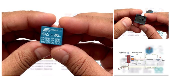 The relay I am looking at is a SRD-05VDC-SL-C. It is very popular relay among Arduino and DIY electronics hobbyists.This relay has 5 pins. 2 for the coil. Middle one is COM (common) and the rest of the two are called NO (Normally Open) and NC (Normally Close). When current flows through the coil of the relay, a magnetic field is created that causes a ferrous armature to move, either making or breaking an electrical connection. When the electromagnet is energized the NO is the one which is on and NC is the one which is off. When the coil is de-energized the electromagnetic force disappears and the armature moves back to the original position turning on the NC contact. The closing and releasing of the contacts results in powering on and off of the circuits.Now, if we look at the top of the relay the first thing we see is SONGLE, it is the name of the manufacturer. Then we see the "Current and Voltage Rating": it is the maximum current and/or voltage that can be passed through the switch. It starts from 10A@250VAC and goes down till 10A@28VDC Finally the bottom bit says: SRD-05VDC-SL-C SRD: is the model of relay. 05VDC: Also known as "Nominal Coil Voltage" or "Relay Activation Voltage", it is the voltage necessary for the coil to activate the relay.S: Stands for "Sealed Type" structureL: is the "Coil Sensitivity" which is 0.36WC: tells us about the contact formI have attached the datasheet of the relay for more information.http://old.ghielectronics.com/downloads/man/20084...
Step 3: Getting Hands on a Relay
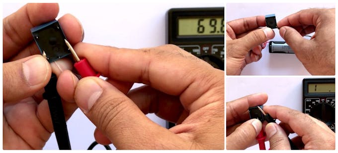 Let’s start by determining the relay coil pins.You can do it either by connecting a multimeter to resistance measuring mode with a scale of 1000 ohm (since the coil resistance normally ranges between 50 ohm and 1000 ohm) or by using a battery. This relay has 'no' polarity marked on it since the internal suppressing diode is not present in it. Hence, the positive output of DC power supply can be connected to any one of the coil pins while negative output of DC power supply will be connected to the other pin of the coil or vice versa. If we connect our battery to the right pins you can actually hear the *clicking* sound when the switch turns on.If you ever get confused in figuring out which one is NO and which one is NC pin, follow the steps below to easily determine that:- Set the multimeter to resistance measuring mode.- Turn the relay upside-down to see pins located at its bottom part.- Now connect one on the multimeter's probe to the pin in between the coils (Common Pin)- Then connect the other probe one by one to the remaining 2 pins.Only one of the pins will complete the circuit and will show activity on the multimeter.
Step 4: Arduino and a Relay
 * The question is "Why to use a relay with an Arduino?"A micro controller's GPIO (general purpose input/output) pins cannot handle higher power devices. A LED is easy enough, but large power items such as light bulbs, motors, pumps or fans required more sneaky circuitry. You can use a 5V relay to switch the 120-240V current and use the Arduino to control the relay.* A relay basically allows a relatively low voltage to easily control higher power circuits. A relay accomplishes this by using the 5V outputted from an Arduino pin to energize the electromagnet which in turn closes an internal, physical switch to turn on or off a higher power circuit. The switching contacts of a relay are completely isolated from the coil, and hence from the Arduino. The only link is by the magnetic field. This process is called "Electrical Isolation".* Now a question arises, Why do we need the extra bit of circuit to drive the relay? The coil of the relay needs a large current (around 150mA) to drive the relay, which an Arduino cannot provide. Therefore we need a device to amplify the current. In this project the NPN transistor 2N2222 drives the relay when the NPN junction gets saturated.
Step 5: Hardware Requirement
 For this tutorial we need:1 x Breadboard1 x Arduino Nano/UNO (Whatever is handy)1 x Relay1 x 1K resistor1 x 1N4007 High Voltage, High Current Rated Diode to protect the micro-controller from voltage spikes1 x 2N2222 General purpose NPN transistor1 x LED and a 220 ohm current limiting resistor to test the connectivityFew connecting cablesA USB cable to upload the code to the Arduinoand general soldering equipments
Step 6: Assembly
 * Lets start by connecting the VIN and GND pins of the Arduino to the +ve and -ve rails of the breadboard.* Then connect one of the coils pin to the +ve 5v rail of breadboard.* Next we need to connect a diode across the electromagnetic coil. The diode across the electromagnet conducts in the reverse direction when the transistor is turned off to protect against a voltage spike or the backward flow of current.* Then connect the Collector of the NPN transistor to the 2nd pin of the coil.* The Emitter connects to the -ve rail of the breadboard.* Final, using a 1k resistor connect the Base of the transistor to the D2 pin of the Arduino.* Thats it our circuit is complete, now we can upload the code to the Arduino to turn on or off the relay. Basically, when +5v flow through the 1K resistor to the Base of transistor, a current of about .0005 amps (500 microamps) flows and turns on the transistor. A current of about .07 amps starts flowing through the junction turning on the electromagnet. The electromagnet then pulls the switching contact and moves it to connect the COM terminal to the NO terminal.* Once the NO terminal is connected a Lamp or any other load can be turned on. In this example I am just turning on and off a LED.
Step 7: The Code
 The code is very simple. Just start by defining the digital pin number 2 of the Arduino as the Relay pin.Then define the pinMode as OUTPUT in the setup section of the code. Finally, in the loop section we are going to turn on and off the relay after every 500 CPU cycles by setting the Relay pin to HIGH and LOW respectively.
Step 8: Conclusion
 * Remember: It is very important to place a diode across the coil of the relay because a spike of voltage (inductive kickback from the coil) is generated (Electromagnetic Interference) when the current is removed from the coil due to the collapse of the magnetic field. This voltage spike can damage the sensitive electronic components controlling the circuit.* Most Important: Same as capacitors, we always under-rate the relay to mitigate the risk of relay failures. Lets say, you need to work at 10A@120VAC, don’t use a relay rated for 10A@120VAC, instead use a bigger one such as 30A@120VAC. Remember, power = current * voltage so a 30A@220V relay can handle up to a 6,000W device.* If you just replace the LED with any other electrical device like fan, bulb, fridge etc., you should be able to turn that appliance into a smart device with an Arduino controlled power outlet.* Relay can also be used to turn on or off two circuits. One when the electromagnet is on and the second one when the electromagnet is off.* A Relay helps in Electrical Isolation. The switching contacts of a relay are completely isolated from the coil, and hence from the Arduino. The only link is by the magnetic field.Note: Short circuits on Arduino pins, or attempting to run high current devices from it, can damage or destroy the output transistors in the pin, or damage the entire AtMega chip. Often this will result in a "dead" pin of the micro-controller but the remaining chip will still function adequately. For this reason it is a good idea to connect OUTPUT pins to other devices with 470Ω or 1k resistors, unless maximum current draw from the pins is required for a particular application
Step 9: Thanks
Thanks again for watching this video! I hope it helps you. If you want to support me, you can subscribe to my channel and watch my other videos. Thanks, ca again in my next video. -
Introduction
----------------
Hi Friends,
I am back again with another Arduino based home automation project. This time I am trying to make my partner's life easy by installing a collision avoidance system in the garage to help her park the car safely without hitting the garage wall.
So, in this video, I am going to use an ultrasonic sensor to calculate the car's distance from the garage wall and display it using green, yellow and red LEDs. The color of LEDs indicates whether to keep moving, slow down, stop or go back.
The total cost of the project is around $20 - $25.
Step 1: Logic

The project has 3 phases
Phase 1: Waiting for the car In this phase the device keeps looking for a moving object within the sensors proximity. If an object enters the proximity then one of the three LEDs turns on based on how far the moving object is. If the object is way too close, then a noise is made to make the moving object aware of the distance.
Phase 2: No car in the garage If there is no object in the proximity then turn off all the LEDs.
Phase 3: The car has stopped moving (Parked in the right spot) If the object has stopped moving and is still in the proximity wait for 20 CPU cycles and then turn off the LEDs.
Step 2: Hardware Requirement

For this very simple project we need:
- A Perfboard
- An Arduino nano/uno (whatever is handy)
- A Red, Green and a Yellow LED (Light Emitting Diode)
- 3 x 220ohm resistor for the LEDs
- One HC-SRO4 Ultrasonic Sensor
- A Buzzer shield or A buzzer and a 100 ohm resistor
- A 220v AC to 5v DC Buck step-down module
- One Female Pin Header Strip
- An Ethernet cable
- Some connecting cables
- A USB cable to upload the code to the Arduino
- and general soldering equipments
Step 3: Assembly

Let start by connecting the LEDs to the board.
Connect the Red LED to pin D2, Yellow LED to D3 and the Green LED to D4 of the Arduino by putting in a 220ohm resistor between the Arduino board and the LEDs. Now lets connect the Buzzer to analogue pin A0. Next, connect the Trig pin of the Ultrasonic Sensor to D5 and the Echo pin to D6 of the Arduino. Once all the modules are connected to the Arduino board, its time for us to connect all the positive and negative pins together. Connect all the positive pins of the modules to the +5v supplied by the Buck Step-Down Module and the negative pins to the -ve terminal of the Module. That's it, we can now upload our sketch to the board.
In this assembly I am using 3 LEDs to display the distance, however you can replace the 3 LEDs with a RGB LED, or you can also use an array of LEDs like an audio level indicator to display the movement of the car.
Step 4: My Setup

OK now lets see what I have made.
I have installed the Arduino, buzzer, the ultrasonic sensor and the three 220 ohms resistors on one Perfboard. The 3 LEDs and the power module is installed on a second Perfboard. I will be covering the LEDs with a translucent cover to give it a nice look.
The 220v power supply will be connected to the screw terminal block. The base unit will then be connected to the LEDs and the power supply with an Ethernet cable.
Step 5: The Code
int trigPin = PD5; // Sensor Trip pin connected to Arduino pin D5

int echoPin = PD6; // Sensor Echo pin connected to Arduino pin D6

int redLED = PD2; // Red LED connected to pin D2

int yellowLED = PD3; // Yellow LED connected to pin D3

int greenLED = PD4; // Green LED connected to pin D4

int buzzer = A0; // Buzzer connected to Analogue pin A0

long TempDistance = 0; // A variable to store the temporary distance

int counter = 0; // Counter value to check if the object has stopped moving

void setup() {

Serial.begin(9600);

pinMode(trigPin, OUTPUT);

pinMode(echoPin, INPUT);

pinMode(redLED, OUTPUT);

pinMode(greenLED, OUTPUT);

pinMode(yellowLED, OUTPUT);

pinMode(buzzer, OUTPUT);

}

void loop() {

long duration, Distance;

digitalWrite(trigPin, LOW);

delayMicroseconds(2);

digitalWrite(trigPin, HIGH);

delayMicroseconds(10);

digitalWrite(trigPin, LOW);

duration = pulseIn(echoPin, HIGH);

Distance = (duration/2) / 74; // Distance in Inches

if(counter < 20){ // Do the rest if the car is still moving

if (Distance > 200) { // Nothing in the garrage

turnThemAllOff();

}

if ((Distance > 55) && (Distance <= 200)) { // Turn on Green LED

digitalWrite(greenLED, HIGH);

digitalWrite(yellowLED, LOW);

digitalWrite(redLED, LOW);

noTone(buzzer);

}

if ((Distance > 15) && (Distance <= 55)) { // Turn on Yellow LED

digitalWrite(yellowLED, HIGH);

digitalWrite(redLED, LOW);

digitalWrite(greenLED,LOW);

noTone(buzzer);

}

if (Distance <= 15) { // Turn on Red LED

digitalWrite(redLED, HIGH);

digitalWrite(greenLED,LOW);

digitalWrite(yellowLED, LOW);

noTone(buzzer);

}

if (Distance < 8) { // Item is way to close - start the buzzer

tone(buzzer, 500);

}

}

if ((Distance == TempDistance) || ((Distance+1) == TempDistance) || ((Distance-1) == TempDistance)){

if(counter >= 20){ // Turn off the lights if the object hasn't moved for 20 cycles (no change in distance)

Serial.println("No movement detected, turning off the lights");

turnThemAllOff();

} else {

counter++;

}

} else {

counter = 0; // Reset counter if there is a movement

}

TempDistance = Distance;

Serial.print(Distance);

Serial.println(" inches");

Serial.print("Counter : ");

Serial.println(counter); delay(500); }

// Function to turn the LEDs off

void turnThemAllOff(){

digitalWrite(redLED, LOW);

digitalWrite(greenLED,LOW);

digitalWrite(yellowLED, LOW);

noTone(buzzer);

}
Start the code by defining the constants and the global variables that will be used throughout the code.
Then define the pin modes in the setup section of the code.
Then create a function to turn off all the LEDs and the buzzer.
Now, calculate the "Distance" in inches by reading the values received from the Ultrasonic Sensor.
Then by checking the value of the "Distance" we will turn on and off the LEDs based on how far the object is. If the distance is greater than 200 then turn off all the LEDs and the buzzer as the object is out of range. Else if it is between 55 and 200 then turn on the green LED. If the object is between 15 and 55 then turn on the yellow LED, and if the object goes closer than 15 inches then turn on the red LED until it reaches 8 inches. When the distance becomes less than 8 start the buzzer along with the red LED.
Next bit of the code is to set the value of the counter based on the cars movement which then decides when to turn off the LEDs. It compares the value of "Distance" with the "TempDistance" and if the values are same (object hasn't moved) then increments the counter. If the object moves any-time during this process the counter is reset to 0. Finally the "TempDistance" is set to the value of "Distance".
Just before comparing the Distances we also need to check if the counter value has exceed 20. I am doing this to stop the below code from executing if the car is in a steady position.
Lastly we just need to add a small delay to our sketch to pause the code for a while.
Step 6: Quick Demo
So this is how I have installed the unit in my garage.
As I walk close to the sensor the light changes from green to yellow to red and ultimately the buzzer goes on when I am too close to the sensor. In my case I have installed the buzzer next to the Arduino however I will recommend you to install the buzzer along with the LEDs. If you want you can also flash the red LED when the buzzer goes on.
So now, my partner can park the car easily without making any assumptions. Doesn't matter how many times she fail her driving test she is not going to break my wall (even when she is drunk). Not that I am asking her to drive when she is drunk (just kidding).
Thanks again for watching this video! I hope it helps you. If you want to support me, you can subscribe to my channel and watch my other videos. Thanks, ca again in my next video.
-
Introduction
---------------
Hi Everyone, This is my 1st Arduino's tutorial video. In this video i am going to show you how to use a LDR or Light Dependent resistor to turn on and off another circuit or a LED.
Wouldn’t it be really cool if whenever a room gets dark, a light bulb automatically turns ON and eliminates the darkness? In this very simple project, I am focusing on eliminating darkness. You can even use this as an emergency lighting system.
Step 1: Principle


The LDR is a special type of resistor which allows a lower voltage to pass through it (high resistance) whenever its dark and higher voltages to pass (low resistance) whenever there is a high intensity of light.
We are going to use a 10k resistor along with the LDR to create a voltage divider circuit. The varying resistance of the LDR is converted to a varying voltage that the analog pin of the Arduino will then be using in its logic.
Step 2: Harware Reqirement

For this very simple DIY Arduino project we need:
- a breadboard
- an arduino uno/nano (whatever is handy)
- LED (Light Emitting Diode)
- LDR (Photoresistor)
- A 10K Resistor for creating the voltage divider and a 220ohm resistor for the LED
- Few breadboard friendly connecting wires
- and a USB cable to upload the code to the Arduino
Step 3: Assembly

- Connect the 3.3v output of the Arduino to the positive rail of the breadboard
- Connect the ground to the negative rail of the breadboard
- Place the LDR on the breadboard
- Attach the 10K resistor to one of the legs of the LDR
- Connect the A0 pin of the Arduino to the same column where the LDR and resistor is connected (Since the LDR gives out an analog voltage, it is connected to the analog input pin on the Arduino. The Arduino, with its built-in ADC (Analog to Digital Converter), then converts the analog voltage from 0-5V into a digital value in the range of 0-1023). - Now connect the other end of the 10K resistor to the negative rail - And the the second (free) leg of the LDR to the positive rail
Pretty much this is what we need for the light sensing. Basic circuits like this can be done without an Arduino aswell. However, if you want to log the values and use it to create charts, run other logics etc. I will recomend an Arduino or ESP8266 or may be a ESP32 for this.
Now, as we want our circuit to do something in the real world other than just displaying the values on the computer screen we will be attaching a LED to the circuit. The LED will turn on when its dark and will go off when its bright. To achieve this we will:
- Place the LED on the breadboard
- Connect the 220ohm resistor to the long leg (+ve) of the LED
- Then we will connect the other leg of the resistor to pin number 13 (digital pin) of the Arduino
- and the shorter leg of the LED to the negative rail of the breadboard
Step 4: The Code

const int ledPin = 13;

const int ldrPin = A0;

void setup() {

Serial.begin(9600);

pinMode(ledPin, OUTPUT);

pinMode(ldrPin, INPUT);

}

void loop() {

int ldrStatus = analogRead(ldrPin);

if (ldrStatus <= 200) {

digitalWrite(ledPin, HIGH);

Serial.print("Its DARK, Turn on the LED : ");

Serial.println(ldrStatus);

} else {

digitalWrite(ledPin, LOW);

Serial.print("Its BRIGHT, Turn off the LED : ");

Serial.println(ldrStatus);

}

}
Thanks again for watching this video! I hope it helps you. If you want to support me, you can subscribe to my channel and watch my other videos. Thanks, ca again in my next Instructable.
-
Hi Everyone,
In this tutorial I am going to show you how to charge a Lithium 18650 Cell using TP4056 chip utilizing the solar energy or simply the SUN.
Wouldn’t it be really cool if you can charge your mobile phones battery using the sun instead of a USB charger. You can also use this project as a DIY portable power bank.
The total cost of this project excluding the battery is just under $5. The battery will addup another $4 to $5 bucks. So the total cost of the project is some what around $10. All components are available on my website for sale for really good price, the link is in the description below.
Step 1: Hardware Requirement

For this project we need:
- A 5v Solar Cell (make sure it is 5v and not anything less than that)
- A general purpose circuit board
- A 1N4007 High Voltage, High Current Rated Diode (for reverse voltage protection). This diode is rated at forward current of 1A with peak reverse voltage rating of 1000V.
- Copper Wire
- 2x PCB Screw Terminal Blocks
- A 18650 Battery Holder
- A 3.7V 18650 Battery
- A TP4056 battery protection board (with or without the protection IC)
- A 5 V power booster
- Some connecting cables
- and general soldering equipments
Step 2: How the TP4056 Work

Looking at this board we can see that it has the TP4056 chip along with few other components of our interest.
There are two LEDs on board one red and one blue. The red one comes on when it is charging and the blue one comes on when the charging is done. Then there is this mini USB connector to charge the battery from an external USB charger. There are also these two points where you can solder your own charging unit. These points are marked as IN- and IN+ We will be utilizing these two point to power this board. The battery will be connected to these two point marked as BAT+ and BAT- (pretty mush self explanatory) The board requires an input voltage of 4.5 to 5.5v to charge the batteryThere are two versions of this board available in the market. One with battery discharge protection module and one without it. Both boards offer 1A charging current and then cut off when finished.
Furthermore, the one with protection switches the load off when the battery voltage drops below 2.4V to protect the cell from running at too low (such as on a cloudy day) - and also protects against over-voltage and reverse polarity connection (it will usually destroy itself instead of the battery) however please check you have it connected correctly the first time.
Step 3: Copper Legs
These boards gets really hot so I will be soldering them a bit above the circuit board.
To achieve this I am going to use a hard copper wire to make legs of the circuit board. I will then be sliding the unit on the legs and will solder them all together. I will put 4 copper wires to make 4 legs of this circuit board. You can also use - Male Breakable Pin Headers instead of the copper wire to achieve this.
Step 4: Assembly


The assembly is very simple.
The solar cell is connected to the TP4056 battery charging board's IN+ and IN- respectively. A diode is inserted at the positive end for the reverse voltage protection. Then the BAT+ and BAT- of the board is connected to the +ve and -ve ends of the battery. (That all we need for charging the battery). Now to power an Arduino board we need to boost up the output to 5v. So, we are adding a 5v voltage booster to this circuit. Connect the -ve end of the battery to the IN- of the booster and +ve to IN+ by adding a switch in between. OK, now lets have a look at what I have made. - I have connected the booster board straight to the charger however I will recommend putting a SPDT switch there. So when the device is charging the battery its only charging and not getting used
Solar cells are connected to the input of the lithium battery charger (TP4056), whose output is connected to the 18560 lithium battery. A 5V step-up voltage booster is also connected to the battery and is used to convert from 3.7V dc to 5V dc.
Charging voltage is typically around 4.2V. Voltage booster's input ranges from 0.9 to 5.0V. So it will see around 3.7V at it's input when the battery is discharging, and 4.2V when it's recharging. The output of the booster to the rest of the circuit will keep it's 5V value.
Step 5: Testing

This project will be very helpful to power a remote data logger. As we know, the power supply is always a problem for a remote logger and most of the times there is no power outlet available. A situation like that forces you to use some batteries to power your circuit. But eventually, the battery will die. Question is do you want to go there and charge the battery? Our inexpensive solar charger project will be an excellent solution for a situation like this to power an Arduino board.
This project can also solve the efficiency issue of Arduino when in sleep. Sleep saves battery, however, the sensors and power regulators (7805) will still consume battery in idle mode draining the battery. By charging the battery as we use it, we can solve our problem.
Thanks again for watching this video! I hope it helps you. If you want to support me, you can subscribe to my channel and watch my other videos. Thanks, ca again in my next video.


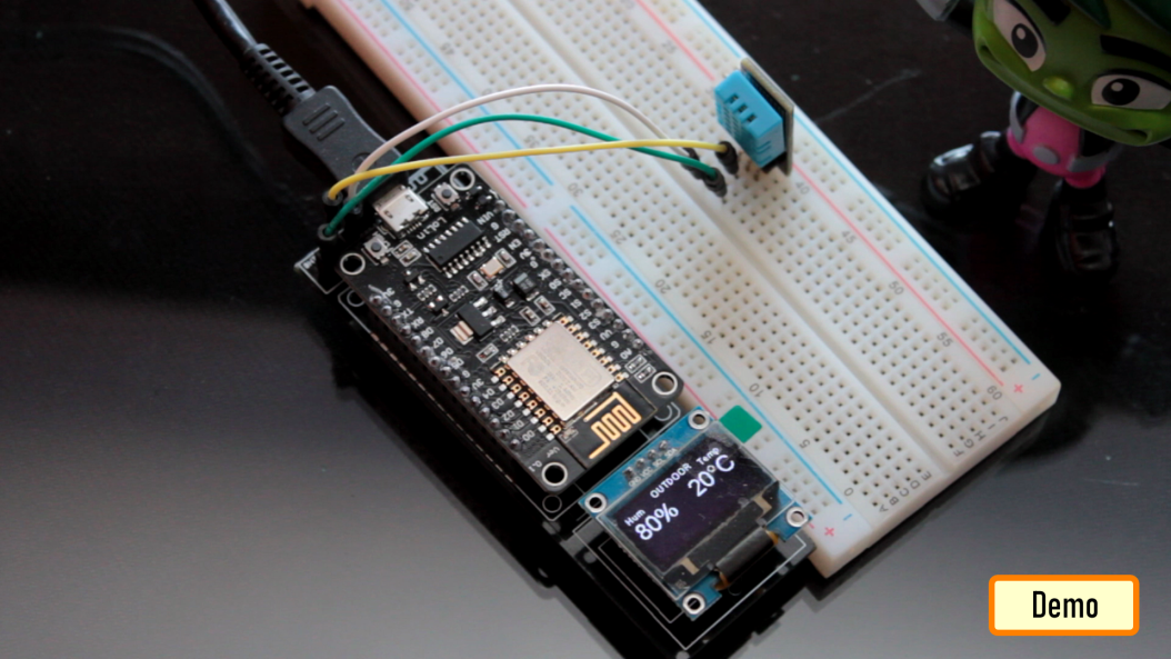

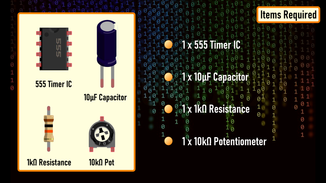


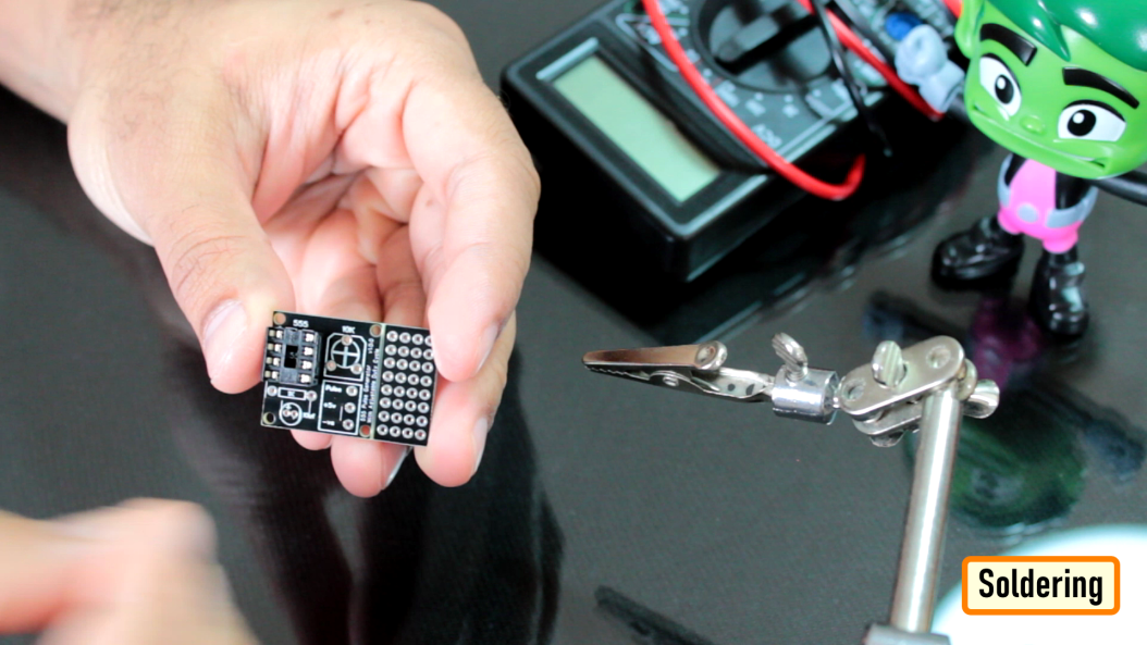


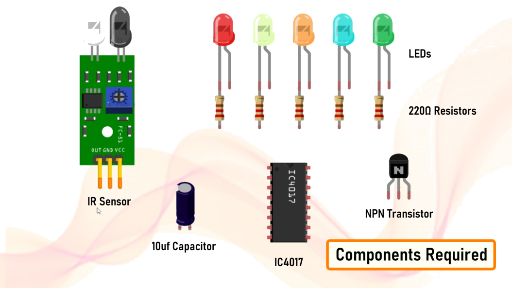


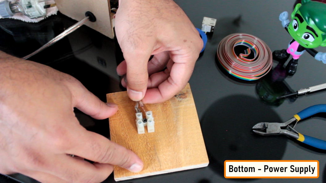
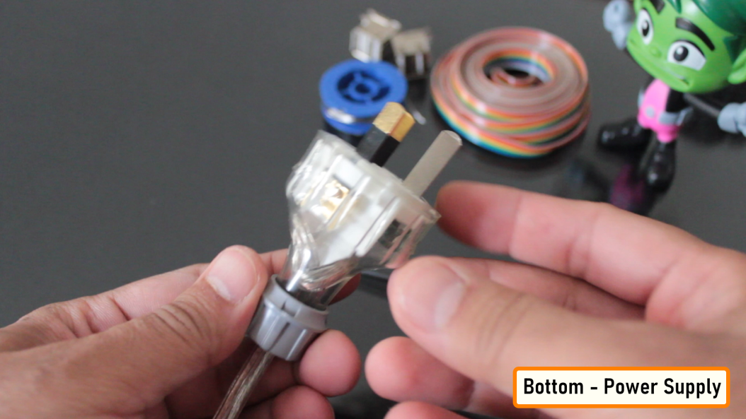


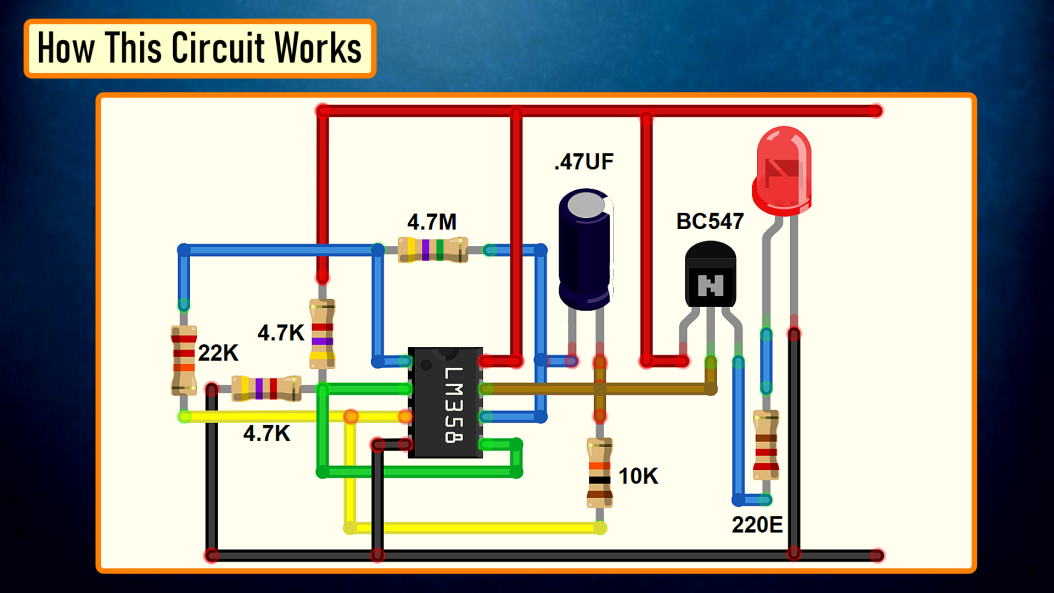

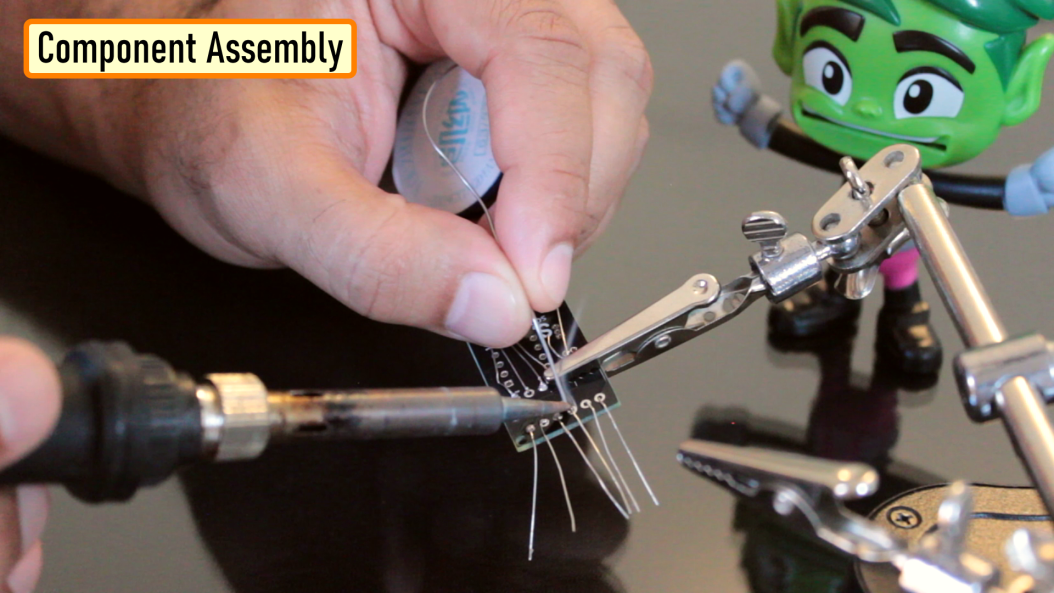


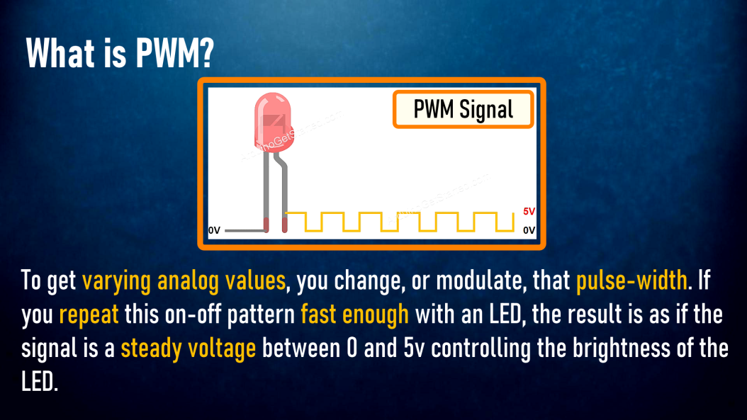
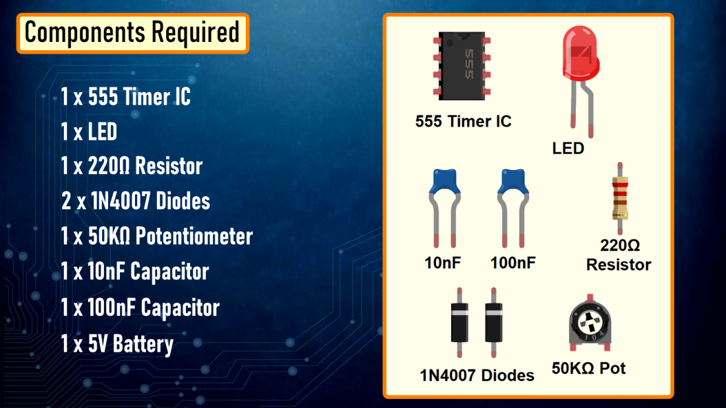


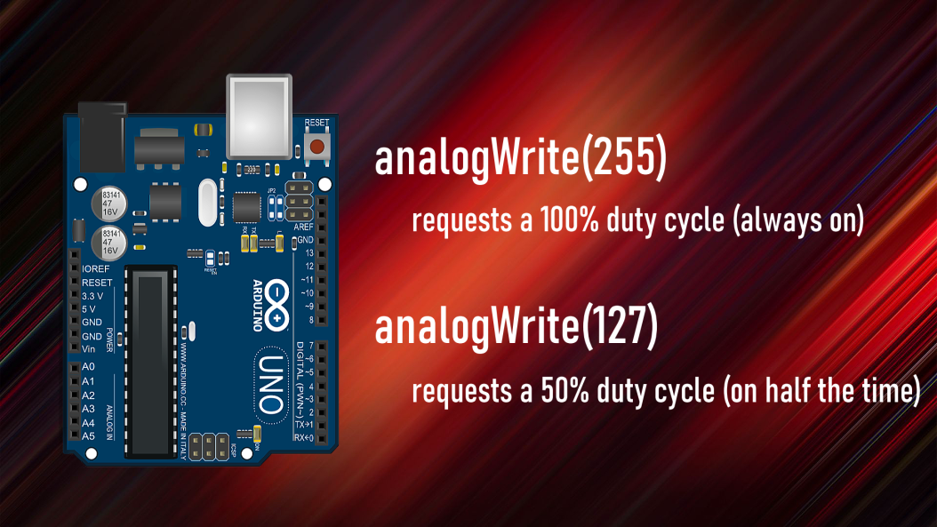


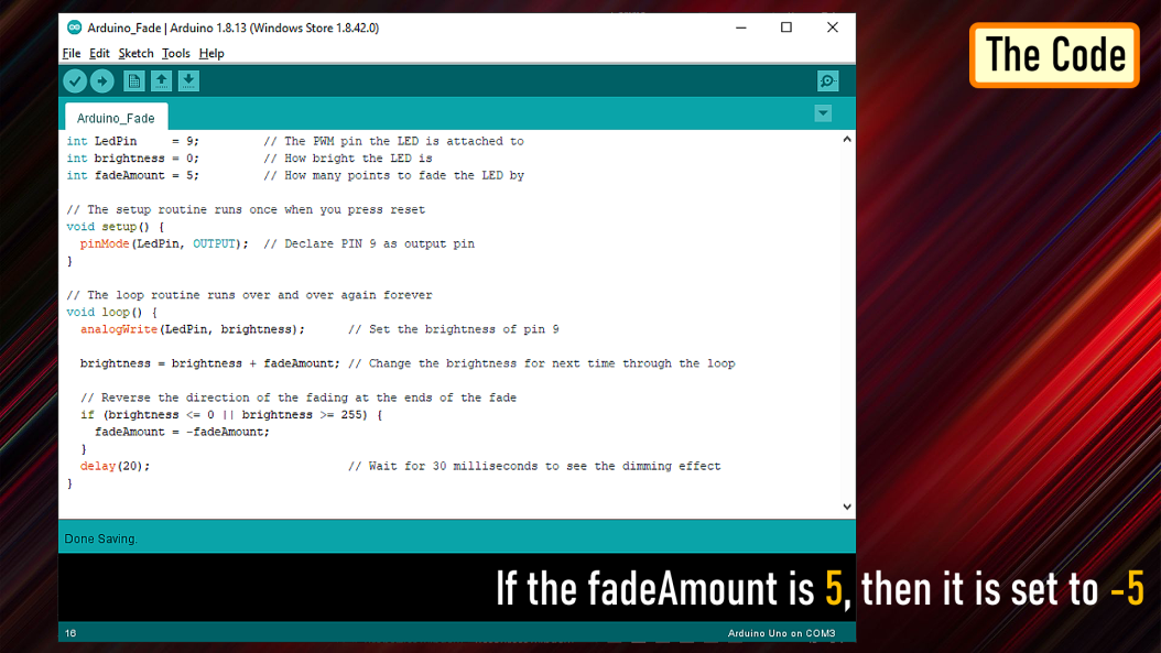
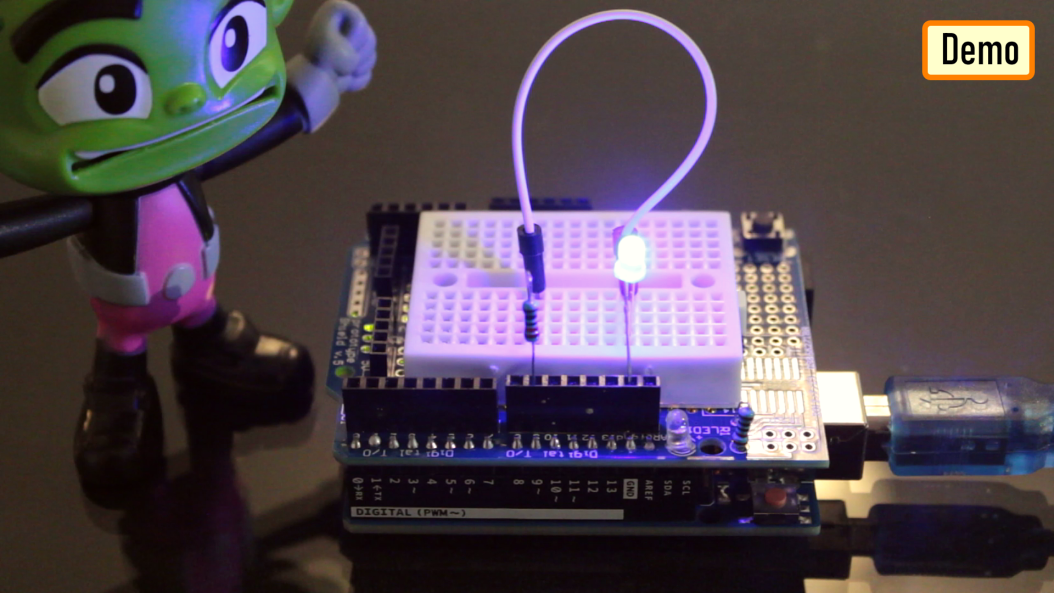
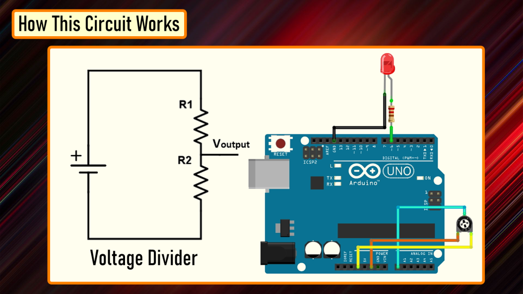
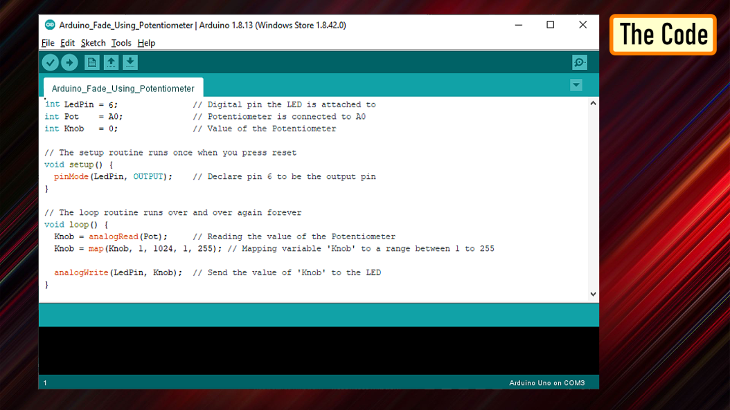


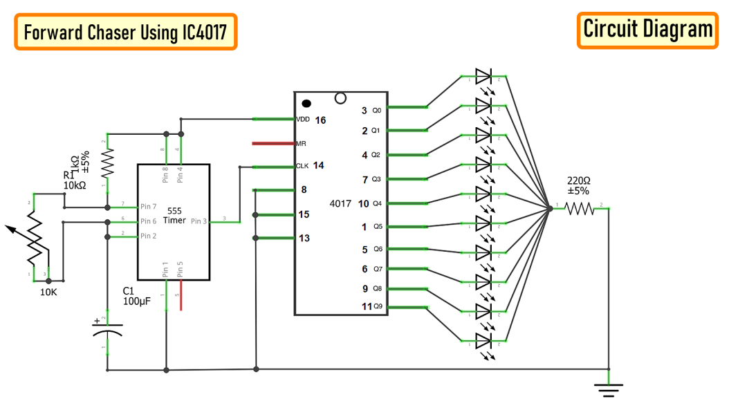
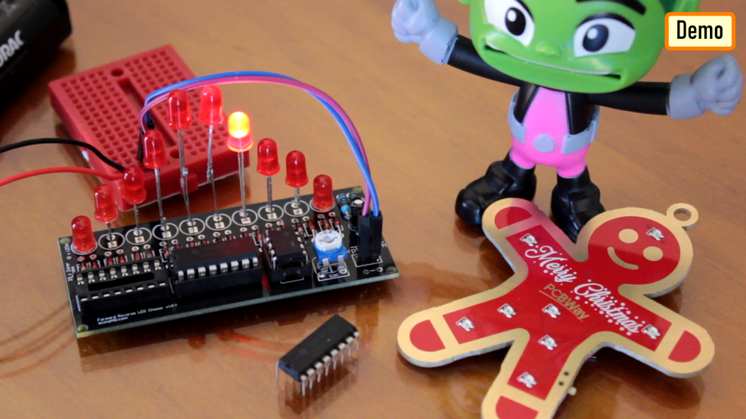


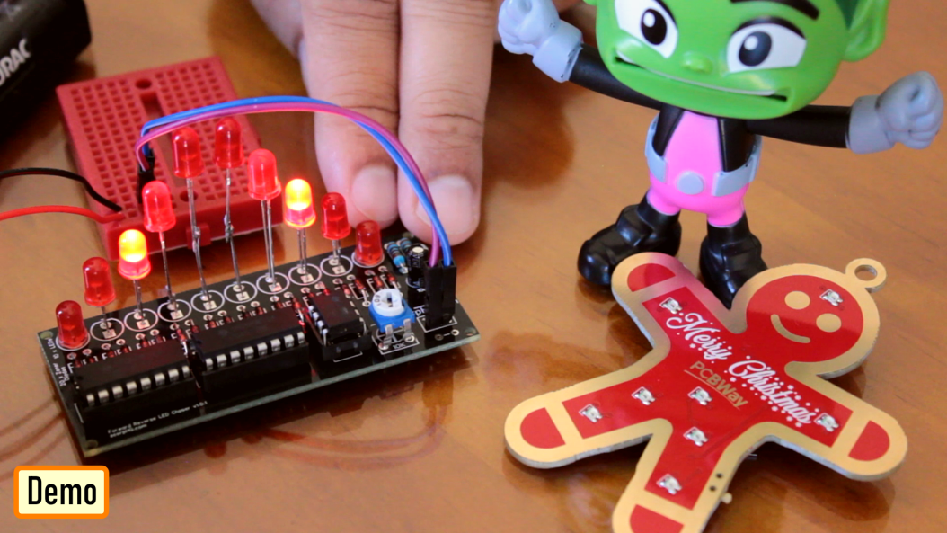


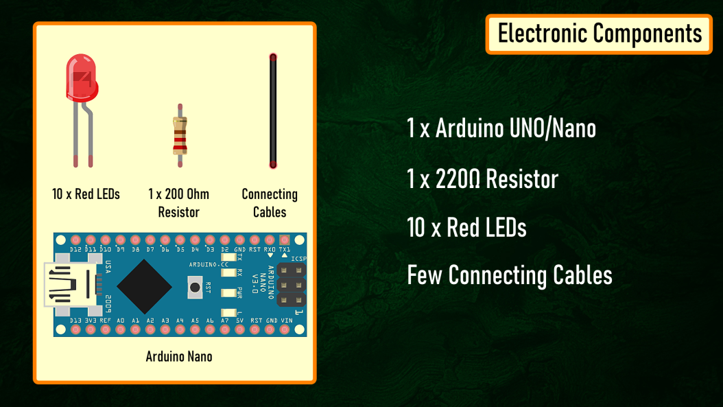


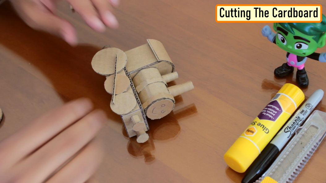


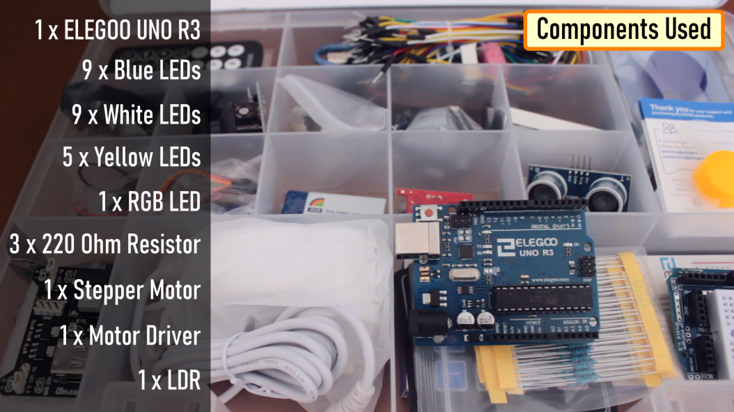


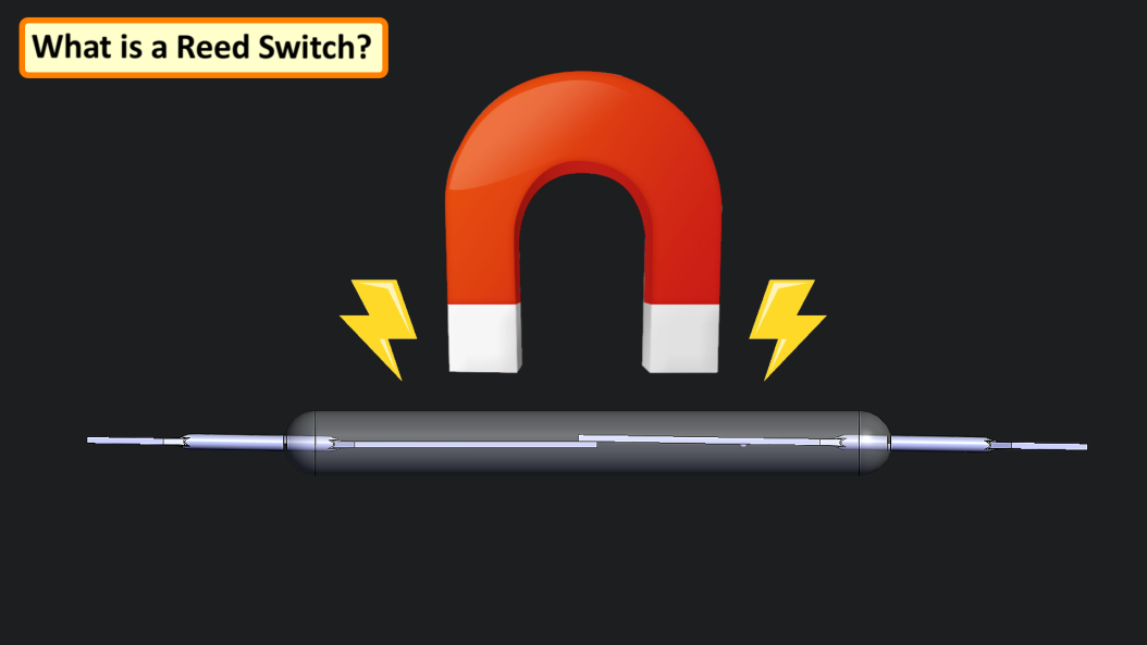

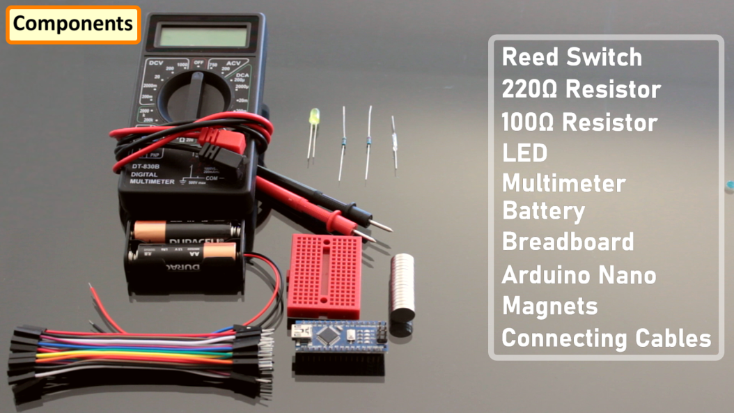
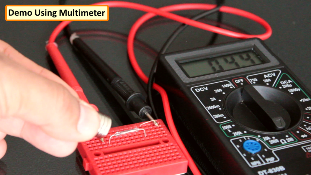
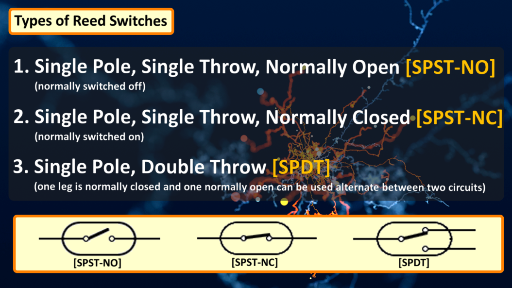
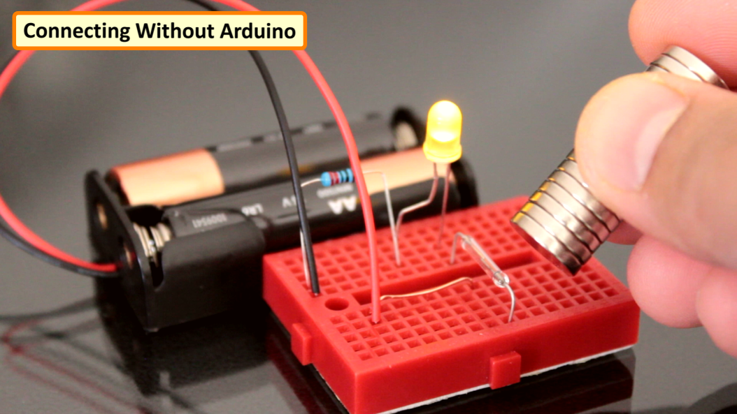
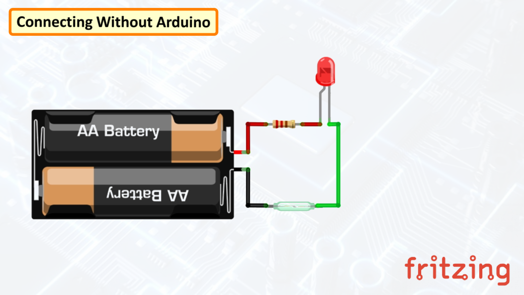

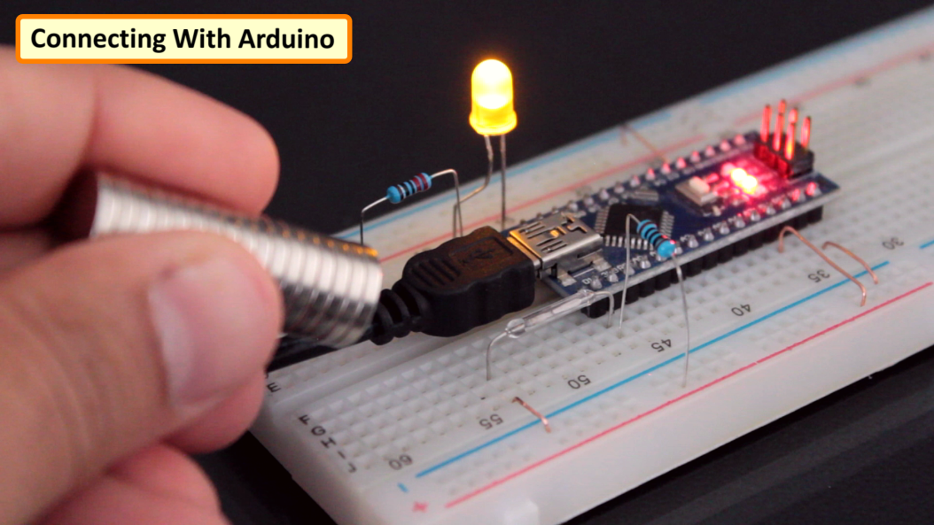


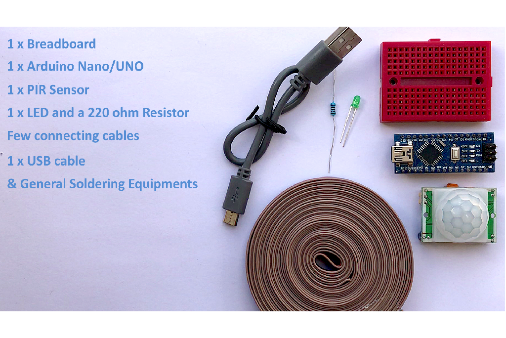


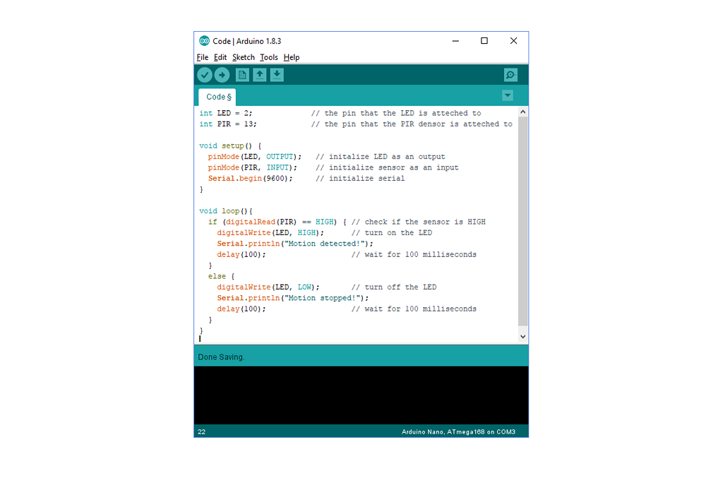


Touchless Covid Free Electronic Dice Using Arduino
in Electronic Gadgets
Posted
Components Required
Circuit Diagram
The Code
Housing Design
Thanks