.png.b1e42692bc15eb316aa8208359d74f30.png)
Aman bharti
-
Posts
31 -
Joined
-
Last visited
Content Type
Profiles
Forums
Events
Everything posted by Aman bharti
-
.thumb.png.2654eb08e8864dfcee99bc0732f95fd2.png) http://www.circuitspedia.com/transistor-as-switch-working-how-transistor-works/ For more detail click here A small Positive current required at the Base terminal for the turning on the transistor. By sending varying levels of current to the base, the amount of current flowing through the collector to emitter may be regulated. When we apply a small Positive supply at base , then Current between emitter and collector will passed and we say that transistor is turn on. A very small amount of current may be used to control a large amount of current, this property is known as amplifier . . A Diode with Parallel of relay coil in reverse connection is necessary for protection the transsistor. This must connected on both PNP and NPN
http://www.circuitspedia.com/transistor-as-switch-working-how-transistor-works/ For more detail click here A small Positive current required at the Base terminal for the turning on the transistor. By sending varying levels of current to the base, the amount of current flowing through the collector to emitter may be regulated. When we apply a small Positive supply at base , then Current between emitter and collector will passed and we say that transistor is turn on. A very small amount of current may be used to control a large amount of current, this property is known as amplifier . . A Diode with Parallel of relay coil in reverse connection is necessary for protection the transsistor. This must connected on both PNP and NPN
-
DIY - AUTOMATIC GARAGE LIGHT
Aman bharti replied to Ashish Adhikari's topic in Electronic Projects Design/Ideas
Automatic Room Light And Security Alarm circuit Using PIR Motion Sensor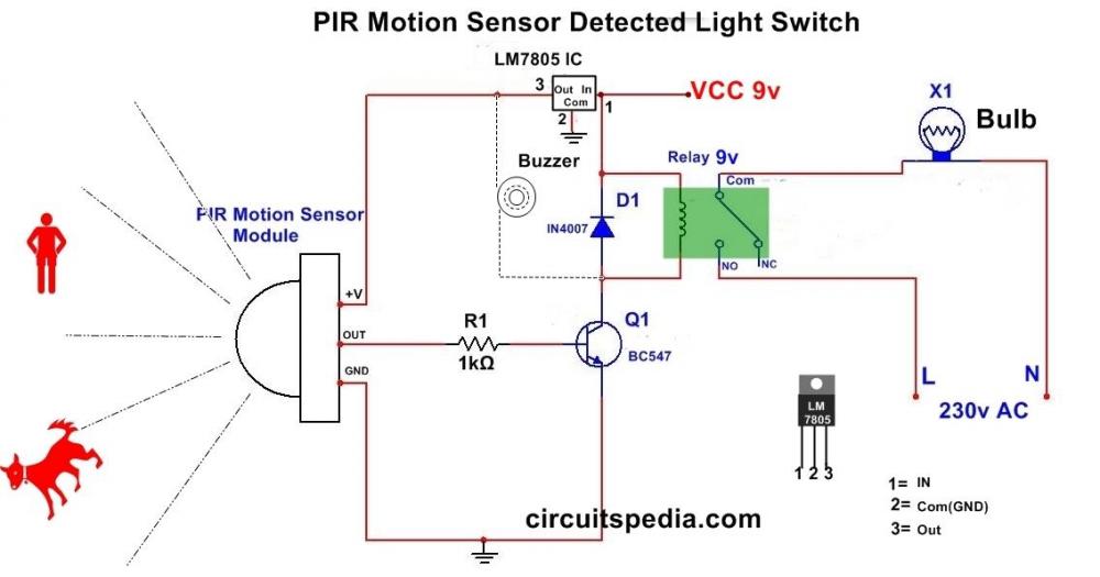
-
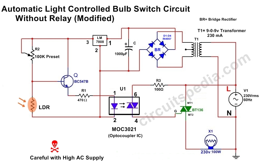
When Light fall on LDR in DAY then the Resistance of LDR goes LOW And at this situation the maximum voltage Dropped With Negative supply (Ground) by cross through LDR and Voltage at the Base of transistor Q1 is Very LOW. When the Voltage goes to very LOW (Below0.7v) at BASE of Q1 then Transistor not get ON and no Power flows between COLLECTOR and EMITTER. Gate Voltagr of TRIAC is LOW. Now TRIAC Remain OFF Because It not TRIGGERED. At Night Time when no light incident on LDR then the internal Resistance of LDR comes HIGH and Very less amount of Power cross through LDR to ground , then the Voltage At base Terminal of transistor become increase (above 0.7v) and now transistor turn ON and current starts flow between Emitter and COLLECTOR. Therefor the Voltage increasing at GATE of TRIAC BT136. As voltage increase at GATE then TRIAC get Triggered . After Triac triggerd it Turn on and Passes the Power Supply between terminal 2 to terminal 1 and Bulb Switched On. For more sensitivity use 2 LDR with parallel. For more detail go to http://www.circuitspedia.com/automatic-light-controlled-bulb-switch-using-without-relay/ And also go to http://www.circuitspedia.com/category/light-operated-switch-circuit/
-
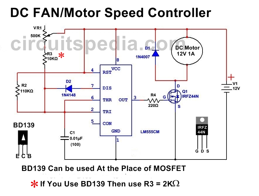
DC FAN Motor Speed Controller Regulator Circuit Works ON Principle of Pulse Width Modulation (PWM) technique , By Using This Technique Controlling Of DC Motor Speed is very Smoothly And Noise Free. Tested on 12v 1 A DC Motor For Full detail with live demo click on http://www.circuitspedia.com/dc-fan-speed-regulator-circuit/ By This Method Smoothly Controlled The Speed Of DC Motor At Negligible Noise BY using This Circuit You can control the speed of DC Fan by tunning the (Potentiometer) volume control variable resistance. These circuits are based on 555 Timer .
-
Clap Switch Circuit Electronic Project Using 555 Timer
Aman bharti replied to jack-chen's topic in Projects Q/A
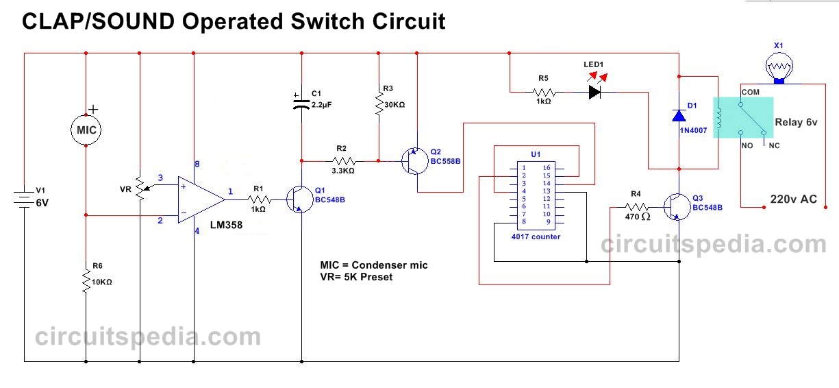
High Sensitive Clap Operated Sound controlled ON OFF Switch Project This clap operated ON OFF Switch circuit is very sensitive and easily operated upto distance of 5 Meter If condenser MIC is fix into a Special type of Cover to Receiving More Sound From Maximum Distance. This Clap/Sound controlled ON OFF Switch circuit consists two ICs , two NPN transistors, One PNP Transistor and some other components. The LM358 and 4017 ic is used. LM358 is an opamp-comparator which has two Op-Amp in a single ic chip. This ic is dual operational Amplifier But in this circuit one op-amp is used. For Full detail click on link http://www.circuitspedia.com/sensitive-clap-operated-on-off-switch-circuit-without-microcontroller/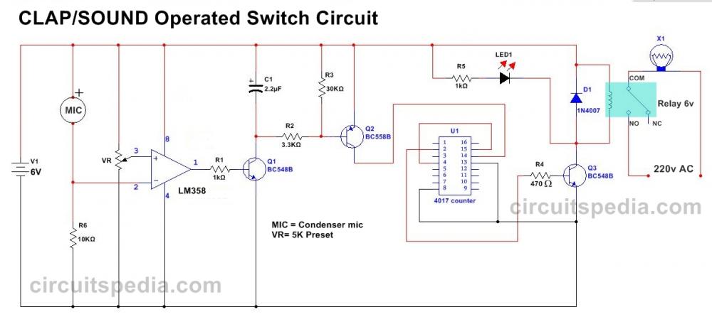
-
websites that an electronics hobbyist should know
Aman bharti replied to amrithmmh's topic in Electronics chit chat
Check For Electronics ideas,circuits and projects on http://www.circuitspedia.com/ -
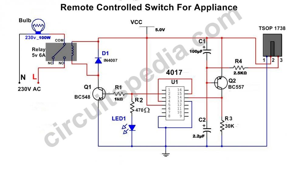
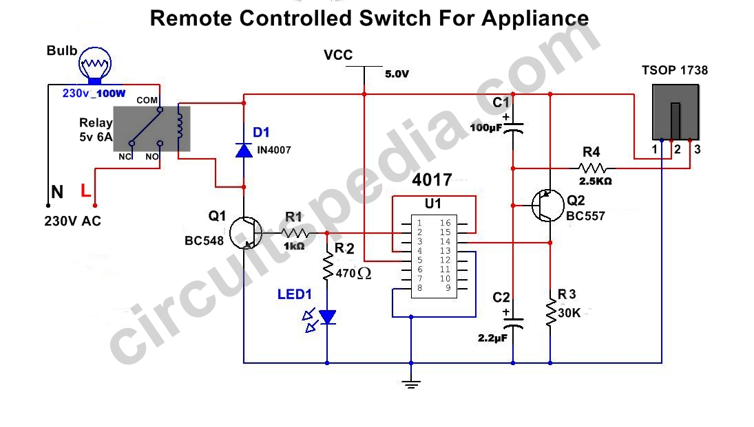
Here a link of very simple and effective remote controlled switch for any appliance (single load) without any microcontroller. Click here This circuit can constructed at home using CD4017 ic and IR sensor. very easily and operated with any TV Remote. ( Tested, Must see the demo video ) http://www.circuitspedia.com/ir-remote-controlled-switch/