
Enrg Tech
-
Posts
6 -
Joined
-
Last visited
Enrg Tech's Achievements
")
Newbie (1/14)
0
Reputation
-
 Enrg Tech changed their profile photo
 -
What is RISC-V? RISC-V has in the recent past attracted the attention of major corporations across the globe like Google, NVIDIA, and Qualcomm among others. It has thrown developers into a frenzy. What exactly is RISC-V though? RISC-V is an instruction set architecture (ISA) that is open source and based on RISC principles. In essence, an ISA is an interface between software and hardware. ISA defines the supported registers, data type, main memory hardware support, and the I/O model of implementation of the ISA. RISC-V was developed at the University of California Berkeley in 2010. It is a simplified architecture thus is well adopted for speed and low power operation. RISC-V based chips are therefore good for commercial applications. Getting started with RISC-V The LoFive FE310 The best way to get hands-on experience with RISC-V is through development boards that are based on RISC-V processors. One such board is the LoFive FE 310 by GroupGets LLC. The board comes with a RISC-V processor that can run up to 320 MHz. It also has 8KB of one-time-programmable memory, 8KB of OTM, 16kb of SRAM, and 16KB of instruction cache. The FE310 also has 3 independent pulse width modulation controllers, UART, SPI, and I2C. The board either has headers soldered to it or it can be soldered onto the carrier board where it can be used as the processor. It has an onboard QSPI flash that is provided through the IS25LP128 module. The flash module is 128Mbit, 16KB module. It can operate at SPI bus speeds of up to 133MHz if used in quad I/O mode. This flash module can be used for storage thus ensuring that there is sufficient space for storing apps or run-time data. The development board also runs on 5 volts which is further converted to 3.3V by the onboard SPX3819M5 which provides up to 500 mA. The FE301 does not draw much current so it can support other devices and sensors. All the design details of the FE301 for instance the schematics and BOM are readily available on GitHub. Setting up the development board There are numerous toolchains available for use with RISC-V depending on the board you choose. RISC-v SDK is available for Linux, Windows, and macOS. There two versions of SDK available, the legacy SDK, and the latest version. Use the latest version as it has a prebuilt toolchain and has OpenOCD for debugging. You can program the development board using several different ways. You could use the standard JTAG on the processor. You can access this through the LoFive-R1 expansion connectors. You can use any programmer that supports JTAG like SEGGER J-LINK. If you can’t find such, you can use a low-cost USB-to-serial converter like the FT223H-56Q mini MDL. The converter hosts all the connections and breakouts needed to interface to the FE301. RISC-V SDK uses general purpose Input/output available on the FT2232H-56Q to come up with the necessary JTAG connection to program the microcontroller. Below are the connections that need to be made between the LoFive-R1 and the ST2232H-56Q You can make these connections directly or using a breadboard. If you are using the development board for the first time, it’s prudent to install a bootloader on board. The bootloader is installed once and could be used to implement upgrades later. Summary RISC-V is ideal for developers intending to use open-source hardware architecture. There are numerous development boards one could use. Setting it up is also not difficult. The only shortcoming with it is that its ecosystem is not as rich as that of other microcontroller platforms. RISC-V is very intriguing though.
-
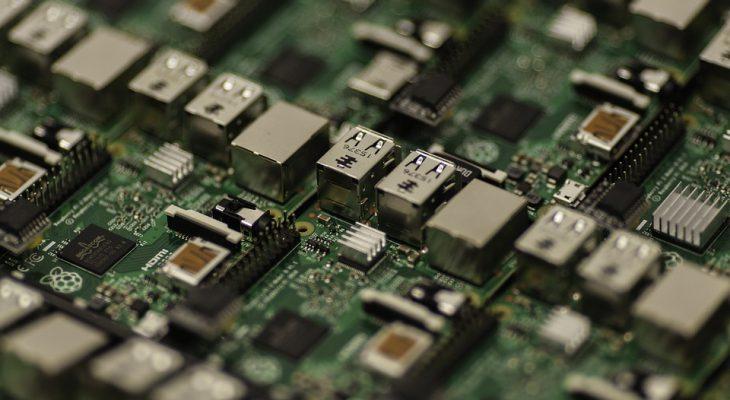
Raspberry Pi is a single board computer manufactured in the UK by the Raspberry Pi Foundation. It was originally designed for education purposes but it has since been adopted by designers, engineers and electronics enthusiasts in developing project requiring more than a basic microcontroller. This article focuses on helping you connect your Raspberry Pi to your PC using an Ethernet cable. Required tools You will require the following: Raspberry Pi 3 Model B Ethernet cable PuTTy Advanced IP scanner SD card (At least 8 GB) Step 1 Install Rasbian on an SD card of not less than 8 GB and then create a blank file called SSH with no extension. Step 2 Plug the SD card into the Rasberry Pi. Connect a 5V power supply to the Rasberry Pi. Step 3 Connect the Ethernet cable to the Raspberry Pi and PC. Step 4 Open Command prompt on your PC. Step 5 In the command line, type in the following command: ipconfig This will prompt your PC to show the windows IP configuration. Step 6 Scroll down until you find Ethernet adapter Ethernet. Find the IPv4 Address in that section and note it down. Step 7 Install Advanced IP scanner and then run it. In it, enter the IPv4 address that you noted in step 6 and then add a hyphen (-) then enter the same IP address while replacing the 1 at the end of the IP with 254. For example, if your IPv4 is 192.168.106.1 then enter 196.168.137.1-196.168.137.254 Step 8 Click Scan located on the top-left. It will show the IP address of your PC and Raspberry Pi. Note down Raspberry Pi’s IP. Step 9 Go to PuTTy configuration and enter the IP address of your Raspberry Pi and then connect to the PC by the PuTTy. Step10 Assign a static IP to the Raspberry Pi. To achieve this, go the command prompt and type in the following command: route –ne This will prompt your PC to show the Kernel IP routing table. Step 11 Find the gateway of eth0 and then note it down Step 12 Go back to command prompt and type in the following command: sudo nano/ etc/ dhcpcd.conf This command will enable you to edit a file called dhcpdd.conf Step 13 Scroll down the file and paste the following code:- interface eth0 static ip_address=192.168.137.5 static routers=192.168.137.1 static domain_name_servers=192.168.137.1 The static ip address is the IP you want to assign to your Raspberry Pi Static routers is the gateway of the Ethernet connection Static domain_name_ servers is the gateway of the Ethernet connection Step 14 Save the file by pressing ctrl+ x and y and then hit enter. Reboot your Raspberry Pi by typing in the following command: sudo reboot Step 15 Go to the PuTTy config and enter the IP you assigned to your Rasberry Pi so as to access it via Ethernet and you are good to go.
-
arduino HOW TO SETUP THE ARDUINO MKR 1300
Enrg Tech posted a topic in Electronic Projects Design/Ideas
The Arduino MKR 1300 comes equipped with the ATMEL SAMD21 bridged with a LoRa module thus allowing for remote IoT applications for instance mining, off-shore rigs, and farms. It has been designed to integrate SAMD21’s low power consumption and high performance while maintaining Arduino’s ease of use. HOW TO SETUP THE ARDUINO MKR 1300.docx -
Microchip UTC2000 Microchip UTC2000 is arguably the best thing to happen to consumer connectivity since Bluetooth. It was introduced in 2014 right after the introduction of USB 3.1 USB type C connectors that have since stolen the spotlight since they are reversible since they embody the same non-oriented connector on both ends. USB-C is small, robust and can handle up to 10 Bits/s, 100W of power and graphics through one single cable. The UTC2000 controller has been designed for USB 2.0 and 3.0 DFP and UFP applications. It can be designed into any existing product to upgrade them to USB Type-C. It offers a means of detecting a USB Type C when its inserted. It also detects the direction the cable is plugged and controls the system to do its job. It comes in small package size and is available in consumer, industrial and extended temperature and automotive versions. Features Transforms an existing USB Type-A design to a USB Type-C DFP or any existing Type-B designing to a USB Type-C UFC. Leverages USB Type-C reversible cable and compactness Can be used with USB 2.0, USB 3.0, USB 3.1 Supports 1.5 A and 3.0 A USB Type-C charging Its compact 3×3 16-pin QFN package Demands minimal design effort Supports USB-C audio adapter Consumer, Industrial and extended temperature versions Applications Laptops USB Hubs Desktop PCs USB Wall Charges Industrial Automotive Monitors
-
TE Connectivity Nector M power connector solution has announced its newly upgraded NECTOR M power system. The power system solution is designed to comply with the UL 1977 directives in conjunction with IEC 61535 standards. TE has just premiered a five-position divider that offers power, signal and regulate connection alternatives for numerous lighting and electrical appliances. TE’s NECTOR M Power System solution is a completely configurable, compact wiring connector and ducting system for the construction industry for illumination and perpetual indoor electrical operations. Its round design decreases installation time significantly, particularly in almost any indoor installation relative to rectangular connector systems. The upgraded system offers electrical service manufacturers with the ability to design, design and build off-site electrical distribution systems, electrical appliances and cable assemblies, resulting in lower labor costs on site, greater efficiency and improved performance for established electrical installations You May Also Like This : ” TE Connectivity USB Type-C Connectors “ Features Multi-functional modular system reduces installation time, on-site labor costs and waste. Same size knocks out diameter for a multi-position 5, 6 and 7 pole connector system, allowing design reliability. Circular form factor requires less space and facilitates easy field installation (with NECTOR M sealed) and simplifies routing during installation. Reduces the risk of building sites for health and safety. Closed barrel pin & crimped socket terminals Specifications IP Seal Level: IP67 (M Sealed NECTOR) Value 600VAC UL. -40oC to 85oC operating temperature Operating voltage: IEC value of 400VAC IP Seal level: IP20 (NECTOR M). The design employed; multi-pole, keyed, modular cable system is ideal for lighting designers, contractors and OEMs requiring more versatility in the distribution of power to different lighting systems and other prevalent electrical appliances within buildings. The availability of wall sockets and dividers makes it much easier to customize the model during installation, but it also makes it easy to modify the system when refurbishing or upgrading the lights. The multi-branch circuit function simplifies wiring in the facilities and simplifies the routing during construction relative to the rectangular electrical connection. The NECTOR M Power System offers different design options for lighting luminaire. The three-pole power systems are suitable to be used in light fixtures for ceilings, walls, pendant and decor that necessitate ground connection in multiunit condos. Applications Lighting Residential Retail display Emergency Entertainment and off-grid Factory-built construction Architectural Commercial Greenhouse lighting Street lighting Industrial Power Distribution Commercial office/retail buildings Residential Pre-fabricated building Hotels Schools Hospitals Shipbuilding