

Jackson1
-
Posts
2 -
Joined
-
Last visited
Content Type
Profiles
Forums
Events
Posts posted by Jackson1
-
-
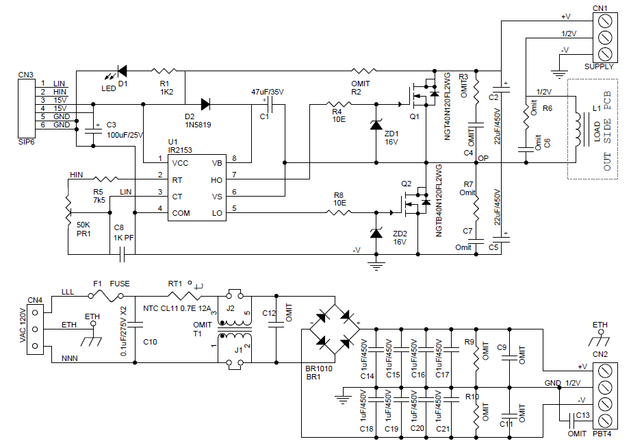
Hi. I am going to try this circuit in the link. But With this circuit what I didn't understand is ground symbols. Where are they connected exactly(not the ETH I know it is for earthing). For the second circuit +V and -V connections are clear but 1/2V is connected to ground through the middle of rectifier capacitors. Should I connect it to somewhere or is it just for reference.
And for the first circuit CN1 and CN2 are connected together respectively and -V is connected to ground symbol. And again is it a reference for us to connect it with ground of 15V dc?
I am new to this forum. I searched and I didn't see any topic regarding this. Thank you for reading.
Half Bridge Driver IR2153
in Projects Q/A
Posted
Thank you for the answer. So I can connect -V pin of CN1 directly to, for example, negative side of C5. And discard second circuit's ground symbol. Is that correct.