-
Posts
54 -
Joined
-
Last visited
Kerrowman's Achievements
-
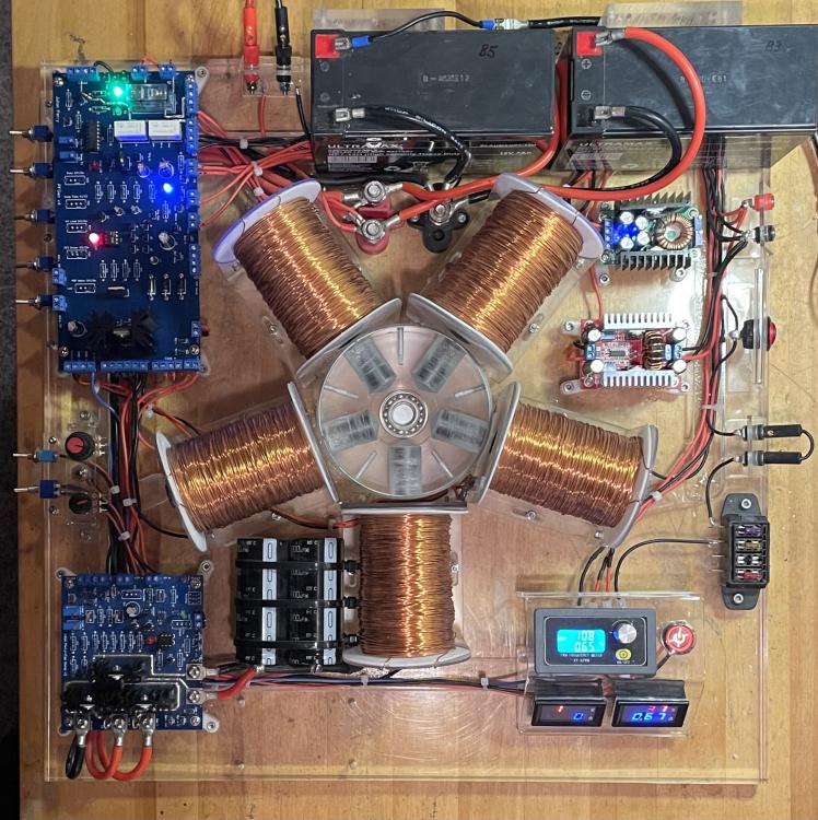
Hi Harry, That’s good of you to do a spice test and if I was starting from scratch then using a microprocessor would have been the way to go. However, I should have made it clear that I already have the cap discharge circuit in operation, that charges up a bank of capacitors to 24V then releases the stored energy as a high current pulse down to 17V. You can see the unit in the bottom left corner of the unit in the pic. So I presently have a system of delivering the HV pulses to the batteries directly (with swapping) or the high current pulses from the ‘cap dump circuit’ but not mixed in the way I have described in my brief and post. Therefore I’m looking to revise the main PCB with some additional elements to do the timed routing I described and not change the cap dump circuit. Hence my suggestion of an SSRelay with a timing circuit. Using an Arduino would take up too much space whereas an SSR and some timing component’s I can fit onto the present PCB format. Incidentally I credited your help in the past, amongst others, in the Acknowledgments in my ‘replication manual’ for this device. This is part of the scientific process for results publication in the future so that any one can replicate the findings. You can see the manual here: https://www.dropbox.com/sh/td55b8675vvqtbg/AADzPSKMOI8q_YM1cFUT2T07a?dl=0 (I have temporarily removed the PCB files while I explore the circuit revision) Assuming the SSR idea is sound then I’m trying to figure out how to set the relay with a short 4ms pulse (as per the earlier diagram) and then reset it after the adjustable period (30-200ms). Perhaps I need a latching relay instead but haven’t found a small DIP 8 format one. Your thoughts are appreciated. Julian
-
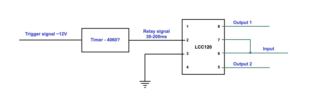
Hi Harry, I appreciate that you probably don't have time to read design briefs like the one I sent so I have proposed a design that hopefully you can comment on. To clarify, the circuit needs to switch an input from one output to another for a set duration (30-200ms) starting when a trigger signal arrives. The sequence of events is as follows - a trigger signal arrives to operate the relay which directs the ‘Input’ to a different output (from ‘Output 1’ to ‘Output 2’) and then, after a preset interval of between 30 and 200ms, directs the input back to ‘Output 1’. For this, I am thinking of using a solid-state relay (LCC120) triggered by some form of timing circuit that will send the trigger signal through to flip the relay at the start of the interval but then send out a low after the set duration to flip the relay back i.e. the input back to output 1. (see attached) If I use a decade chip like to 4060BE, then it will only go high after a set number of oscillations from its inbuilt oscillator and so won’t operate the relay at the start, so I need a timer that is enabled by the ‘tigger signal’ to operate the relay and then, after a preset interval, turns off the relay so it reverts to its original output. Can you suggest an alternative timer method or any additional components to make this work? Thank you Jules
-
Hi Harry, It will be a lot easier if I attach a two page design brief that explains what I’m trying to do in modifying my current setup. As you will see the duration of the ‘divert’ needs to be adjustable. Julian Design Brief (Combined pulses).pdf
-
What is the best way to divert some 0.5-1.7kV inductively generated flyback pulses from one destination to another and then back again after a short period without using a relay, which would probably be too slow and inaccurate to set the duration of the ‘divert’? Can this be done with an FET/ IGBT or is there a better and more obvious way? Thanks
-
ryanda2948 started following Kerrowman
-
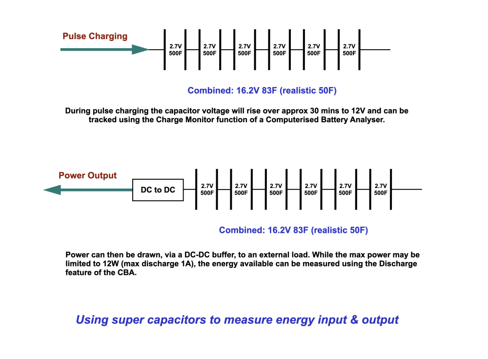
Hi Harry, Yes, 1/2 CV squared is a quick way to calculate the energy in a capacitor but there are three reasons why using a CBA is preferable and helpful, bedsides the fact that I already have one for the extensive Coefficient of Performance tests done over the past six months, as detailed in the report I sent via the link in the pm. Firstly, knowing the exact capacitance of the 6 supercapacitors I have in series is not easy to determine. 6 x 500F caps in series should be 83F but they are often only about 300F each so it’s more likely to be around 50F. Sticking my meter across them doesn’t give any reading even after 30mins due to their large value. Secondly, the CBA provides me with the detailed graphical information for the total energy dissipated through the electronic load as well as the process and rate of charging etc. Lastly the CBA gives me a safe way to dissipate and release the energy they contain to bring them safely down to zero. I calculated that a 50F bank of caps at 15V ‘contains’ 5.63kJ which, if there was a short across the terminals could generate over 50kW of power in 0.1s so having a way to discharge them and see the process is also desirable. I acknowledge that ESR is a factor but that mostly applies to AC circuits and this is DC all the way. It’s good to know that I shouldn’t need any additional buffering between the caps and the CBA. Julian
-
Ok but if I’m using an electronic load to discharge the capacitor (so I can measure the energy it can deliver) once it’s been charged, then do I need the buffer of a DC-DC converter. Won’t the electronic load (https://www.westmountainradio.com/product_info.php?products_id=cba5) serve that function?
-
Hi Harry, I hadn't realised that super capacitors were now so cheap and so I have come up with a plan to test the energy in and out as shown in the attached graphic. Am I right in thinking that after charging the capacitors, if I shorted the output terminals of the DC-DC converter that there wouldn't be a massive discharge? Julian
-
Hi Harry, Thanks for your thoughts. I think it’s only fair that I give you some context for my query. For the last few years I have been researching and testing a hypothesis regarding energy harvesting using inductively generated HV transients. Here pulses are delivered to a battery and certain energy gain effects have been observed. If you are interested to read an internal report about this work then I have sent you a link via a pm. I will be writing a full scientific paper in the new year after I have completed the power tests. The capacitor issue is a way to add further validity to my findings. In order to observe the process independently of battery chemistry, it is proposed to replace the batteries with capacitors. I know that capacitors charge up very well with the pulses as they formed part of a ‘cap dump circuit’ that was integrated into the system as part of the testing to compare dV/dt effects with dI/dt ones. The question is, can a capacitor be used in the same way as a battery, which is in effect a big capacitor, and controlled in a similar way to a one? Your suggestion of the DC-DC converter (either Buck or Boost?) sounds an interesting option and worth exploring but what would be a suitable capacitance to replace an 18Ah Lithium Phosphate battery and a what sort of cost? As an aside I note you enjoy woodwork. Besides photography I also do wood turning that keeps me very grounded. I look forward to your thoughts. Regards Julian
-
Hi there, I would like to know if I can use a large capacitor to store energy on the way that I currently do with an 18Ah lithium battery? My understanding is that with the minimal internal resistance of a capacitor, they can discharge their energy very fast even though the energy density is not as big as that of a battery. With this natural tendency for a fast discharge then how could one regulate the output current to a steady dependable rate without inserting some resistance to increase the RC value very significantly. Also there will surely be energy wasted as heat through any such resistance. So to be more specific to my application, I am currently storing energy from HV transients in an 18Ah LiFePO4 battery and then later using that energy to run a small load. From past experience I know that my HV transients can quickly charge up a bank of capacitors (50mF) but would it be feasible to use that energy, with additional energy from a PSU for example, to run the circuit that is producing the transients in the first place? Is that an option or are there too many technical hurdles, due to the nature of capacitors, to make that efficient and workable? I also expect such large value capacitors (1-2F) would be very expensive. Thanks
-
Measurement accuracy is one issue yes but it does not explain why my device cannot function quite as normal when I’m measuring current with this meter compared to when it’s not in the circuit.
-
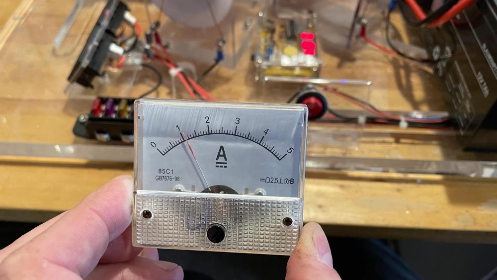
The clamp meter gives about 1.1 so close to the analogue meter. The current here is steady and continuous and not pulsed. The DVM reads about 0.95 so there must be something in the DVM that is getting in the way?
-
Interestingly, if I replace the DVM with an analogue meter it’s all fine. Do DVMs have other input components that can ‘get in the way’?
-
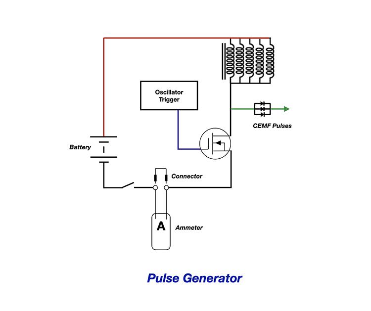
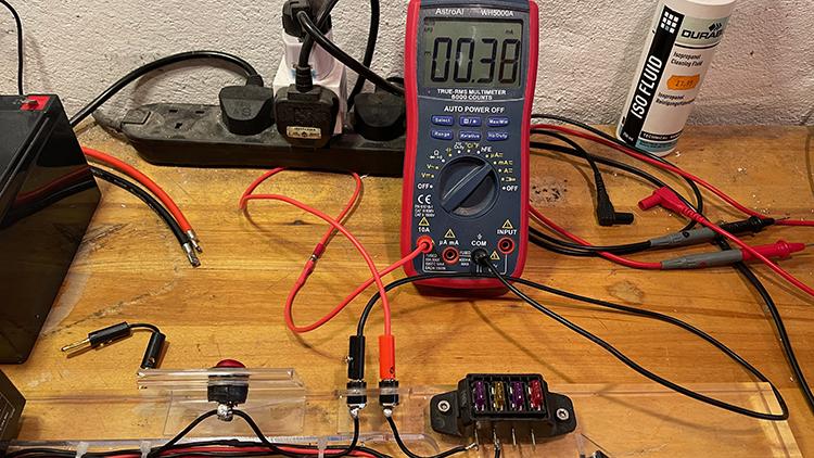
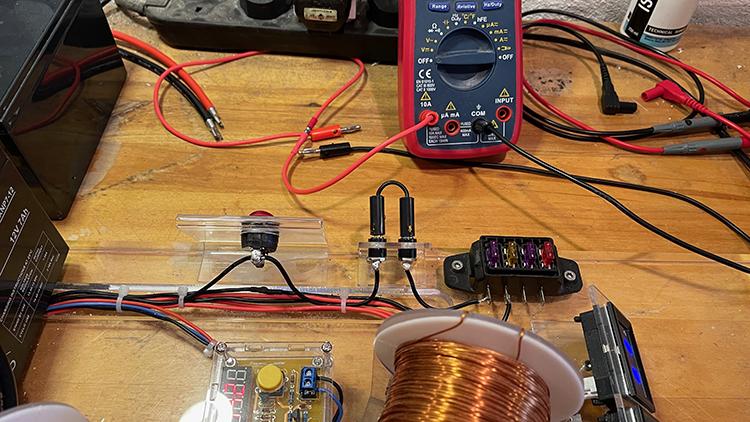
Hi there, I am trying to measure the current in a circuit by putting a digital ammeter inline, as in the diagram, after removing a connecting link that is also shown. When the connector link is in, the circuit works fine but when the meter is in it doesn't work well at all, implying that there is some significant resistance from the meter. In practice it looks like this: In the two photos, first I have have some jumper leads plugged in and the circuit runs normally. Plug in the meter instead and, while there is some current flowing, there is not enough for the system to function properly. As I understand it the ammeter should offer minimal resistance to the circuit and so should not interfere with it during it’s measurement process. Using another meter, when disconnected, the resistance of the red plug through to the black plug via the meter set to 'A' is 0.1 Ohms. I do have a clamp meter but I am expecting to use a desktop digital meter that will take readings automatically at regular intervals without my having to remember to stop and take one. Am I doing something wrong here and how can I obtain a good reading without interfering with the circuit's operation? Thanks
-
Hi there, I’m looking for a computerized battery analyzer that will achieve the functions shown below and show graphical plots on a Windows 11 laptop in real-time. I have been looking at the CBA iV from West Mountain Radio that would have been fine and do all I need and at a reasonable price, but it doesn't appear to work with laptops, only desktop computers. The link for this is here: https://www.radioworld.co.uk/cba_iv_pro_58250-1015-computerized_battery_analyzer?ref=StoreYa&utm_source=stry&utm_medium=trafb&utm_term=pla-296303633664&utm_campaign=storeya51 What I am measuring is the effect on the charging process for some small 7Ah AGM batteries, but later also regular car batteries, of a generator that produces high current pulses from a capacitive discharge circuit. So what I would like to be able to do are the following: 1: Release a known amount of charge (Ah) or energy (Watt-mins) from a fully charged battery; so acting as an electronic load 2: Observe the charging profile of the battery with a Volts vs time graph on a laptop as it is being charged by my pulsing system 3: Be able to measure the power and current delivered to the battery being charged So I don't need the device to be a power supply but instead to monitor what is happening as the battery charges and also to be a load at times. I have looked at a few devices (see below) but while they can clearly act as loads, I'm not so sure about the other requirements? ET5410 Professional DC Electronic Load Programmable Digital Control Battery Capacity Tester Electronic Loads 400W 150V 40A Measurement & Analysis Instruments from Tools on banggood https://banggood.onelink.me/zMT7/s4nr3ceq DL24/P 150W/180W 2.4" DC USB Tester Electronic Load 18650 Car Battery Capacity Monitor Discharge Charge Power Meter Checker https://a.aliexpress.com/_vdYJ8j Thank you
-

Circuit to increase CEMF spikes
Kerrowman replied to Kerrowman's topic in Electronic Projects Design/Ideas
The link with Time is that V= L.dI/dt so the Voltage produced is determined by the rate of change of the current for a given Inductance. If 200kV is what is coming out of the simulator then something is not quite right with what’s going in to it, or an assumption somewhere. 😬


