Search the Community
Showing results for tags 'iot'.
-
This is MicroPython project developed using Ameba RTL8722. MicroPython is offically supported on Ameba RTL8722, so through this demo video, we will see how easy and fast it is to develop a simple server socket on Ameba, which would then control other peripheral to perform other tasks. Here we are using a client socket code running on PC to send a 'Hello, world' string via the WiFi network, Ameba receives it and if it is indeed 'Hello, world' then it will blink the LED. Check out the demo video down below, https://youtu.be/pEMkwvw-r18 Code used: #!/usr/bin/env python3 #PC Client code import socket HOST = '192.168.1.152' # The server's hostname or IP address PORT = 80 # The port used by the server with socket.socket(socket.AF_INET, socket.SOCK_STREAM) as s: s.connect((HOST, PORT)) s.send(bytes('Hello, world','utf8')) #Ameba Code from machine import Pin from wireless import WLAN import time import socket wifi = WLAN(WLAN.STA) wifi.connect("MPSSID","upyameba") led = Pin("PB_4",Pin.OUT) s = socket.SOCK() port = 80 data = ' ' s.bind(port) s.listen() conn, addr = s.accept() while True: data = conn.recv(1024) print(data) if data == b'Hello, world': print('turn on LED 1') for i in range(6): led.toggle() time.sleep_ms(200) if not data: break
-
 Bluetooth Low Energy is energy conversing wireless procotol that help IoT microcontroller to save a great deal of power as compared to using WiFi. Here we use Realtek's RTL8722 dual-band WiFi and BLE 5.0 IoT microcontroller to demo how to output PWM signal to a RGB led over BLE UART Materials Ameba D [RTL8722 CSM/DM] x 1 RGB LED Android / iOS smartphone Example Introduction In this example, a smartphone app is used to transmit commands over BLE UART to control the PWM outputs and change the color of a RGB LED. Refer to the other example guides for detailed explanations of the BLE UART service. Procedure Connect the RGB LED to the RTL8722 board following the diagram, the common LED pin may need to connect to 3.3V or GND depending on the type of LED (common anode / common cathode). Ensure that the required app is installed on your smartphone, it is available at: – Google Play Store: https://play.google.com/store/apps/details?id=com.adafruit.bluefruit.le.connect – Apple App Store: https://apps.apple.com/us/app/bluefruit-connect/id830125974 Open the example, “Files” -> “Examples” -> “AmebaBLE” -> “PWM_over_BLEUart”. Upload the code and press the reset button on Ameba once the upload is finished. Open the app on your smartphone, scan and connect to the board shown as “AMEBA_BLE_DEV” and choose the controller -> color picker function in the app. Using the color selection wheel, saturation, and brightness sliders, choose a desired color and click select to send the RGB values to the board. You should see the RGB LED change to the matching color. Code Reference The RGB values are sent as three consecutive bytes prefixed by “!C” characters. The “!” exclamation mark is used to indicate that the following data is a command, and the “C” character is used to indicate that the data is RGB values. The received UART message is checked in the callback function for “!C” first, otherwise it is treated as a regular message and printed to the serial terminal.
 -
There are a lot of online IoT platform out there, google is one of the first few platforms that provide free and easy-to-use IoT services to maker and developer, here is an example using Realtek' RTL8195 development board for Google IoT service, Google Cloud IOT Preparation Ameba x 1 Example This example illustrates how to use Cloud IoT Core on AMEBA. It doesn't need extra Library and use WiFiSSLClient and PubSubClient to connect. Before compiling to Ameba, we need to register and set up Google Cloud IoT Platform. Please refer to Standard SDK examples: https://www.amebaiot.com/google-cloud-iot/ Open the example “File” -> “Examples” -> “AmebaMQTTClient” -> “google_cloud”, we can get project_id, registry_id, device_id and private.pem.key if Google Cloud IoT Platform has been set up. In the example, fill in amebago-193913 for project_id, amebago-registry for registry_id and amebago-rs256-device for device_id as follows. Remember to fill in private.pem.key for privateKeyBuff. Compile and download to Ameba after updating these parameters. Then open the terminal, start to connect to Google Cloud and it shows ” This is Ameba's x message!!” when the connection is successful as follows. The "x" is the increment value for each loop. Verify: Key in with Google Cloud SDK Shell: $ gcloud beta pubsub subscriptions pull --auto-ack \ projects/amebago-193913/subscriptions/amebago-subscription The following are the messages sent by Ameba. Code Reference In setup(), we set up Certificate, which means setting RootCA and Private Key wifiClient.setRootCA((unsigned char*)rootCABuff); wifiClient.setClientCertificate(NULL, (unsigned char*)privateKeyBuff); In loop(), each loop checks the Internet status and re-connect to it when the environment has a problem. if (WiFi.status() != WL_CONNECTED) { while (WiFi.begin(ssid, pass) != WL_CONNECTED) { delay(1000); } Serial.println("Connected to wifi"); } It requires mqtt_id , clientPass and pub_topic to publish: produce mqtt_id: mqtt_id = (char *)malloc(strlen("projects/") + strlen(project_id) + strlen("/locations/us-central1/registries/") + strlen(registry_id) + strlen("/devices/") + strlen(device_id) + 1); sprintf(mqtt_id, "projects/%s/locations/us-central1/registries/%s/devices/%s", project_id, registry_id, device_id); produce clientPass(via JWT Format): clientPass = jwt_generator((unsigned char*)privateKeyBuff, project_id, 3600*1); produce pub_topic: pub_topic = (char *)malloc(strlen("/devices/") + strlen(device_id) + strlen("/events") + 1); sprintf(pub_topic, "/devices/%s/events", device_id); MQTT Server setting: client.setServer(GOOGLE_MQTT_SERVER, GOOGLE_MQTT_PORT); client.setPublishQos(MQTTQOS1); client.waitForAck(true); Start to connect to google cloud if (client.connect(mqtt_id, clientUser, clientPass) ) { .......... for(int i = 0; i < count; i++){ .......... sprintf(payload, "This is Ameba's %d message!!", i); ret = client.publish(pub_topic, payload); .......... } .......... client.disconnect(); } free(mqtt_id); free(pub_topic); Publish the payload with client.publish method. Remember to disconnect, free mqtt_id and pub_topic buffer。
-
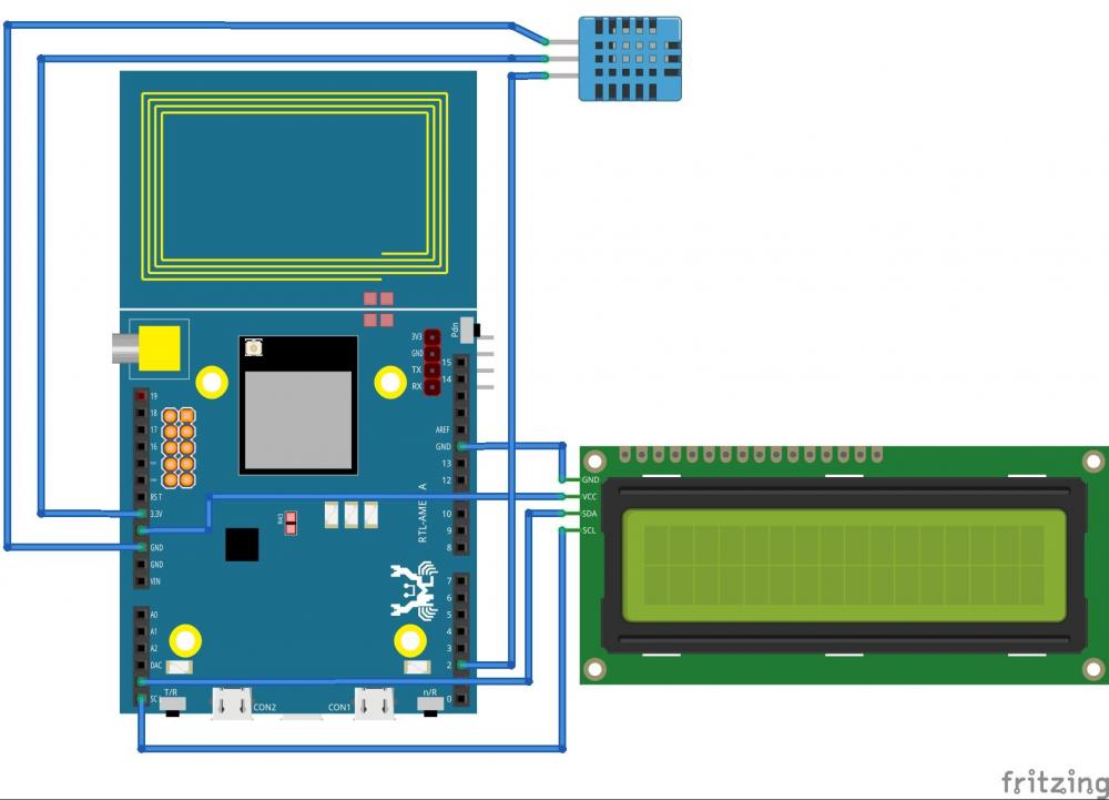
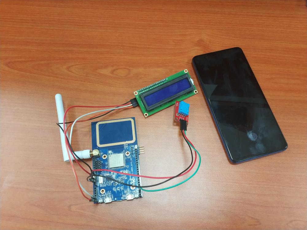
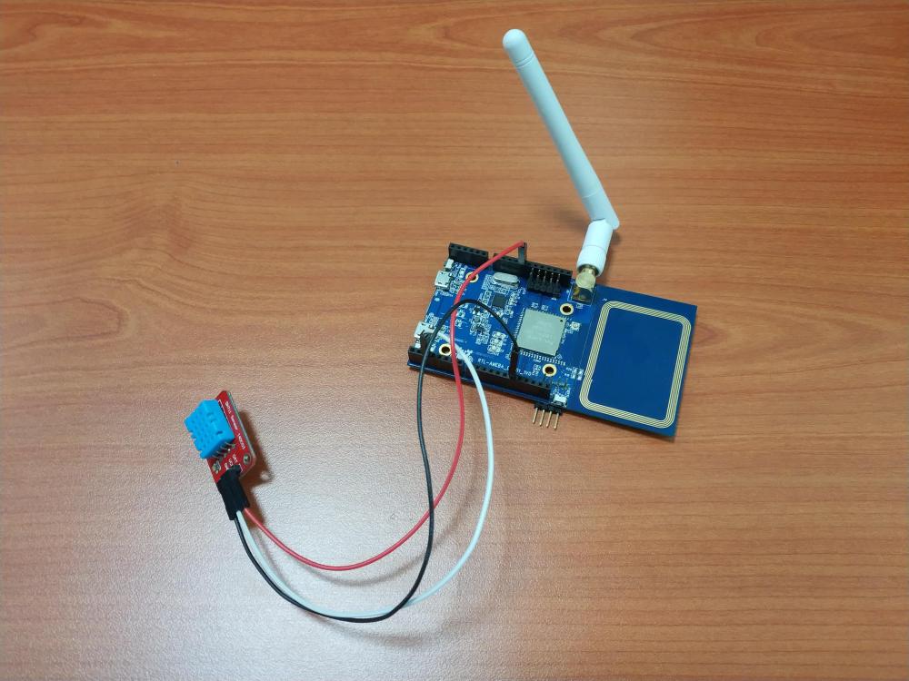
As clean energe continue to attract huge attention due to the foreseeable demise of fossil fuel, harvesting clean energy , particularly solar energy, for embedded system make sense in many IOT applications for its low power consumption and sometime awkward placement, this example will guide you through how to harvest solar energy for an IOT project, Solar Panel – Upload Temperature And Humidity Data To LASS System Preparation Ameba x 1 DHT11 x 1 Solar Panel (1W) x 1 Lipo rider pro x 1 Li-Po battery (1100 mAh) x 1 DS3231 RTC x 1 AMS1117-3.3V x 1 (Optional) Solar Panel The solar panel we use is: http://www.seeedstudio.com/depot/1W-Solar-Panel-80X100-p-633.html The difference of the models with different power is the time it takes to charge the lithium battery. In general, solar panels with 1W power is sufficient for the weather in Taiwan. Lithium Battery In the night, we use lithium battery to provide power. Take the occasional cloudy days into account, we choose the lithium battery of size 1100mAh. Note that batteries with capacity smaller than 500mAh are not recommended. Lithium Charge-Discharge Module In the daytime, besides providing power to Ameba, we expect the solar panel to supply power to charge the lithium battery. On the other hand, if the solar panel cannot provide enough power, we rely on the lithium battery to supply power. Therefore, we need a Charge-Discharge Module for the lithium battery. Here we use Lipo Rider pro, it uses JST 2.0 joint. There are a number of alternatives: Lipo Rider: http://www.seeedstudio.com/depot/Lipo-Rider-v13-p-2403.html PowerBoost 500C: https://www.adafruit.com/product/1944 PowerBoost 1000C: https://www.adafruit.com/product/2465 DS3231 RTC We use DS1307RTC library supports DS1307/ DS1337/DS3231, here we use DS3231. AMS1117-3.3V The default output of Lipo Rider Pro is 5V, hence can be connected to Ameba directly. If you wish to provide only 3.3V to Ameba module to save power, you can use AMS1117 to step-down the voltage to 3.3V. Example In this example, we use solar panel to supply power for Ameba. When the power output of the solar panel exceeds the power demanded by Ameba, surplus power charges the lithium battery, which can supply power at night. Open the sample code in "File" -> "Examples" -> "AmebaMQTTClient" -> "lass_for_dht_plus_ps_nfc" Note that when you choose to supply power only to Ameba module, the 3.3V on Ameba board would be unavailable. For the modules that require 3.3V power, you need to step-down the voltage to 3.3V to supply power. If you do not want to use AMS1117, you can supply power to 5V directly (note this enables DAP and leads to additional power consumption). Another noteworthy point is that the antenna in the figure is cut down from Ameba, and is connected to Ameba through wires. To run the example, a few settings should be done: Please provide the ssid/password for WiFi connection. The clientId of LASS is set to FT_LIVE_12345678 by default, please replace it with a different value. Compile and upload the sample to Ameba and press reset button. Wait for a while, then you should see the data in the website: http://g0vairmap.3203.info/map.html The sample code uses the location of Realtek by default. For the NFC function, you can use your android phone to scan the NFC antenna to download the NFC APP from google play. (Or you can download from: https://play.google.com/store/apps/details?id=com.realtek.sensortag) After the APP is installed successfully, use your phone to scan the Tag to read the latest temperature and humidity. Press the button at the bottom to get the temperature and humidity information of the day. Energy consumption analysis The power efficiency of the solar panel The measure of brightness here is Illuminance(LUX), light with different wave length have different illuminance. We use Halogen bulbs to simulate sun light. In Taiwan, in the time between 10am to 2pm, the measured illuminance is about 100 LUX on average. At 4pm, the measured illuminance is about 10 LUX on average. Using 100W Halogen bulb, we measure 10k LUX illuminance in distance 20cm, and 100k LUX in distance 5cm. However, the shorter the distance between light source and solar panel, the higher the temperature of the solar panel. As the temperature of solar panel increases, the power efficiency decreases. We keep the distance 20cm in our experiment here. When the illuminance is 100k LUX, the solar panel outputs 210mA current, with voltage 4.8V. 4.8V x 0.21 A = 1.008 W. When the illuminance is 10k LUX, the solar panel outputs only 40~60mA current Power consumption of NFC In this example, the NFC function is kept available when Ameba enters deepsleep. The power consumption of NFC is about 7mA, which is considerably high compared with deepsleep. Power consumption of RTC Normally, RTC uses battery to hold the time precision. However, when RTC is connected to Ameba, Ameba enables its I2C interface by default, which leads to additional 2mA power consumption. Total power consumption If you step-down power source to 3.3V and connect to Ameba module, the measured current in deepsleep is 12mA, and long-term average is 13mA. If you supply 5V power to Ameba, the measured current in deepsleep is 17mA, long-term average is 18mA. Besides NFC and RTC, voltage step-down module and LED light also consumes power. Not considering the power consumed by the battery charge-discharge module, assume that the solar panel provides 40mA current and the 1100mAh lithium battery has used up half of its capacity. Then we need 550mA / (210mA - 13mA) = 2.8 hours to fully charge the lithium battery. If the solar panel cannot provide sufficient current output to supply power for Ameba and the lithium battery, and the Ameba board relies on the lithium battery as power source. Then the battery can provide power for 550 mAh / 13mA = 42 hours. Code Reference The program is composed by previous examples. The execution flow is as follows: At the beginning, we setup watchdog and activate a GTimer to feed/kick watchdog every second, and if the total execution flow is not completed in 30 seconds, go into deepsleep. Note that we put the WiFi connection part in the rear of the flow. Since turning on WiFi consumes relatively more power, to design low-power project, it is recommended that put WiFi-unrelated parts at the beginning of the execution flow.
-
IR (Infrared) is often used in our remote controller to control TV, fans and light etc for its easy-to-use and affordibility. However, we can also use it for some other purposes like sending and receiving sensor data in a close range, and Realtek's Ameba RTL8722 equiped with dual band WiFi and BLE 5.0 also comes with special designed registers just for IR transmissions, here is demo, IR – Infra-Red Receiver And Emitter Preparation Ameba x 1 Grove - Infrared Receiver x 1 Grove - Infrared Emitter x 1 Principle Infra-red refers to the invisible light with wavelength 770nm~1mm. It is commonly used in our life, for example the remote control in our home. In general, the infra-red emitter and receiver specify the frequency used in transmission. There are some widely used frequency regulations such as NEC, Philips RC5, RC6, RCMM, Toshiba, Sharp, JVC, Sony SIRC,...etc. Among them, NEC uses 38KHz frequency and is commonly used in appliances. The demodulator in the IR receiver outputs 0V when it receives signals with specified frequency, otherwise it outputs 3.3V(or 5V). For the IR emitter, it needs to emit signal with specified frequency (generally PWM signal), since IR receiver would only respond to the specified frequency, The figure below shows a complete Infra-red signal emitted from the IR emitter: First it sends the start signal, which contains a start high and a start low. Start high is PWM signal with frequency 38KHz. Start low is digital signal output, usually we output 0V signal for start low. Then it sends the data a byte at a time. A byte is sent in the order from LSB (Least Significant Bit) to MSB (Most Significant Bit). A bit 1 is represented by a 560us-long PWM signal, and stop for 1.69 ms. A bit 0 is represented by a 560us-long PWM signal, and stop for 560 us. When the data transmission is finished, send a bit 1 as the stop bit. At the receiver side, through demodulation, the received PWM signals are converted to general digital input: And those signals other than PWM signals, are put at 3.3V (or 5V). Example: IR receiver For implementation, Ameba uses a GPIO Interrupt pin and hardware Timer 4. Open the example in "File" -> "Examples" -> "AmebaIRSendRecv" -> "recv" In this example, we use Grove Infrared Receiver, other infra-red receiver works similarly. In general, we will use 3 pins: VCC(connects to 3.3V), GND, RX. In the example, we connect RX to D3 (which has GPIO Interrupt function). Wiring diagram: RTL8710 Wiring diagram: Compile the code and upload to Ameba, then press reset. If you have NEC remote control in hand, you can test that whether the Ameba IR receiver works. Or you can follow next example to use another Ameba board to make an IR emitter yourself. Note that the received messages of the IR receiver will be shown on the serial monitor. Example: IR emitter A typical IR emitter has 2 pins. However, the Grove Infrared Emitter has 3 pins: VCC, GND and TX. In practice, we can only use GND and TX. To transmit 38KHz signal in real time, Ameba uses TX of UART to emit the signal. Hence, when we are using Ameba to emit IR signal, D0 pin (UART RX) would be unavailable. Following is the wiring diagram: However, since the TX of UART is usually on 3.3V, this leads to unnecessary power consumption. Therefore, we rearrange the wires to connect Ameba UART TX to the GND pin of Grove Infrared Emitter, and connect the signal wire of emitter to 3.3V: RTL8710 Wiring Diagram: In this case, when the emitter is not emitting signal, GND and TX are both at 3.3V, voltage difference is 0. Open the example "File" -> "Examples" -> "AmebaIRSendRecv" -> "send". Compile and upload to Ameba, and press reset. In this example, the IR emitter emits signal every 2 seconds. You can test it with the previous IR receiver example. Code Reference We refer to Grove infra-red Send Recv library to design our API. The original source code can be found here. Although the API of Ameba looks similar to that of Arduino, the implementation details is different. IR receiver First, we have to specify the pin used to receive data. Since it needs GPIO interrupt, we have to select a pin with GPIO interrupt function. We use D3 pin in the example. IR.Init(pinRecv) In the loop, we keep checking if there is incoming signal. IR.IsDta() When we receive signal, put the data into user buffer. IR.Recv(dta) The format of the buffer: Byte 0: Data length of whole packet. Byte 1: Length of start high, unit is 50us. Byte 2: Length of start low, unit is 50us. Byte 3: The stop length after the PWM signal when the data bit is 1, unit is 50us. Byte 4: The stop length after the PWM signal when the data bit is 0, unit is 50us. Byte 5...: Data. IR emitter Use Send() API to transmit data. The first argument is the data to be transmitted, and the second argument is the frequency(unit is 1K), in the example we use 38KHz. IR.Send(dtaSend, 38) The transmission format of the data: Byte 0: Data length of whole packet. Byte 1: Length of start high, unit is 50us. Byte 2: Length of start low, unit is 50us. Byte 3: The stop length after the PWM signal when the data bit is 1, unit is 50us. Byte 4: The stop length after the PWM signal when the data bit is 0, unit is 50us. Byte 5: Length of data to transmit. Byte 6...: Data to transmit.
-
iot Use Firebase to Push Notification from MCU to Smartphone
MENG XI posted a topic in Electronic Gadgets
MCU is often considered not powerful enough to communicate with smartphone, yet many projects actually works a lot better if MCU can communicate with smartphone in some way. RTL8722 WiFi+BLE microcontroller from Realtek can do just that with the help of Firebase Messaging Service, and here is how it is done, Use Firebase To Push Messaging Services Preparation Ameba x 1 Android Studio Smart phone with Google Play Service x 1 Example In the era of the popularity of smart phones, people often receive reminders from specific apps. In this example, we will teach how to use Google Firebase to send messages from the Ameba Client to mobile phones. First, we use Firebase Cloud Messaging (FCM) as a cross-platform messaging solution that lets you deliver messages for free and reliably. With FCM, you can notify your client application (App) to sync emails or other data. You can send a message to drive user engagement. For instant messaging content, a message can transfer up to 4KB of payload to the client application. The FCM implementation includes two main parts for sending and receiving: 1. A trusted environment, such as Cloud Functions for Firebase or an application server for building, locating, and sending messages. 2. Receive iOS, Android or Web (JavaScript) client applications for messages. You can use Admin SDK or HTTP&XMPP API to send messages.To test or send marketing or engagement messages with powerful built-in targeting and analytics, you can also useNotifications composer We know that Ameba can send messages to specific apps as long as it implements the http client function. First of all, we must first set up an environment for developing Android apps. Please download Android Studio first on Android official website. https://developer.android.com/studio/install Then we can use the Android example provided by Firebase to download Firebase Quickstart Samples. https://github.com/firebase/quickstart-android Open Android Studio and click on Import Project, select the messaging project in Firebase Quickstart Samples. Since we won't use other functions, we can only choose the messaging project. Android Studio will need to install the SDK and Google repository for the first time to start the messaging project. You can refer to the following page for update. https://developer.android.com/studio/intro/update Wait until the required components for compiling the app are installed, you can open the messaging project, and Android Studio comes with the Firebase registration function. As shown above, open the toolbar and click Tools->Select Firebase. Open Firebase Assisant in the right pane, then see Cloud Messaging, select Set up Firebase Cloud Messaging to start the registration process. Click Connect to Firebase Then bring out the page, and click on Firebase on the left and log in to the Gmail account. Once you log in, you will be taken to the Firebase homepage. Let's keep the homepage first, we need to go to the Firebase Console and go back to Android Studio. We can see that when the webpage is successfully logged in, Android Studio also brings up the login information dialog box, click connect to Firebase You can see Dependencies set up correctly in the right pane and see a google-service.json file in the left pane, indicating that the app has been registered successfully. At this point, you can connect your phone to your computer (press Shift+F10) or press the Runs App in the toolbar. Please note here that Firebase requires a mobile phone to provide Google play service (GPS) service. An example of not being able to use Firebase without installing Google Play. As shown above, the messaging app is installed and executed successfully on the phone. Click LOG TOKEN at this time. There will be a Token ID, which is the Access Token required to send the message, representing the ID of the FCM service APP installed on a particular phone. This ID is unique and will be reassigned when the app is removed and re-installed. It means that the message can be sent to a specific phone. The FCM service can also push messages to a NEWS (Topic). This section can be found in Firebase topic-messaging: https://firebase.google.com/docs/cloud-messaging/android/topic-messaging Therefore, we need to save this Access Token, return to Android Studio as shown below, select Debug at the log level of the Logcat. When you press the LOG TOKEN button on the App, Logcat will print out the Access Token ID. We will save the code after the InstanceID Token: in the Log message. Then we have to go back to the page that was brought when we first logged into Firebase. Click in the upper right corner to go to the console At this point, You can see that Android Studio has just built the messaging project for us in the operation. Click to enter the messaging project with settings page, as shown above. Select Set up Go to the Settings page and select the Cloud Messaging page. We will see the Legacy server key. This Server key also needs to be used in the program. Let's save it and start editing the code. Open the example "File" -> "Examples" -> "AmebaWiFi" -> "Firebase.ino" As shown above, ACCESS_TOKEN and SERVER_KEY are defined in the reverse white part, that is, the ACCESS token ID that we just saved from the APP and the Server Key saved in the Firebase console page. We fill in the two sets of IDs, compile and upload them to Ameba. Press the Reset button and open the terminal. Connect to FCM Server after connecting to AP After showing Connect to Server successful, it means that the FCM connection is successful and the message will be sent. During the process, HTTP/1.1 200 OK will be received to indicate that the message is successfully pushed. At this time, the mobile phone screen is opened and the App receives the message from Ameba. Code Reference Firebase.ino This example uses the HTTP protocol to push messages. Users can learn the payload format from the Firebase development website. https://firebase.google.com/docs/cloud-messaging/send-message The main payload format in the program is as follows. The user can freely change the Title and Body of the message. Body represents the content of the message. char const* payload = "{" \ "\"to\": \"" ACCESS_TOKEN "\"," \ "\"notification\": {" \ "\"body\": \"Hello World!\"," \ "\"title\" : \"From Realtek Ameba\" " \ "} }" ; setup() if (client.connect(server, 80)) { Serial.println("connected to server"); // Make a HTTP request: sprintf(message,"%s%s%s%s%s%d%s%s%s","POST /fcm/send HTTP/1.1\nContent-Type: application/json\nAuthorization: key=",SERVER_KEY,"\nHost: ",HOST_NAME,"\nContent-Length: ",strlen(payload),"\n\n",payload,"\n"); printf("\nRequest:\n%s \n",message); client.println(message); client.println(); } The sprintf part puts the payload into the HTTP POST content and sends the message out after connecting to the FCM Server. loop() while (client.available()) { char c = client.read(); Serial.write(c); } Waiting for the response from Server and printing out the response -
ameba WiFi Microcontroller working with UDP -- Ameba Arduino
MENG XI posted a topic in Electronic Gadgets
Use Ameba As UDP Server When surfing on internet, most of us are using TCP as its reliable and secure, however, UDP could also shine in some other area where speed is more important than integrity, and here is how Realtek's Ameba RTL8722 WiFi+BLE microcontroller works with UDP, Preparation Ameba x 1 Example In this example, we connect Ameba to WiFi and use Ameba to be an UDP server. When Ameba receives a message from UDP client, it replies "acknowledged" message to client. Open the WiFi Web Server example. “File” -> “Examples” -> “AmebaWiFi” -> “WiFiUdpSendReceiveString” Modify related information, including ssid, pass, keyindex Compile the code and upload it to Ameba. After pressing the Reset button, Ameba connects to WiFi and starts the UDP server with port 2390. After the UDP server starts service, Ameba prints the "Starting connection to server" message and waits for client connection. As to the UDP client, we use "sockit" program in the computer to connect to UDP server. Choose client mode and fill in the IP of UDP server (which is the IP of Ameba) and port 2390, then click "UDP Connect". After the connection is established, fill in "Hello World" in the Buf 0 field in sockit and click "Send". Then you can see the Ameba UDP server replies "acknowledged". Code Reference Ameba uses the WiFiUdp class which is compatible with Arduino WiFi Shield, so the Refer to the Arduino tutorial for detailed information about this example. https://www.arduino.cc/en/Tutorial/WiFiSendReceiveUDPString First, use begin() to open an UDP port on Ameba. https://www.arduino.cc/en/Reference/WiFiUDPBegin Use parsePacket() to wait for data from client. https://www.arduino.cc/en/Reference/WiFiUDPParsePacket When a connection is established, use remoteIP() and remotePort() to get the IP and port of the client. https://www.arduino.cc/en/Reference/WiFiUDPRemoteIP https://www.arduino.cc/en/Reference/WiFiUDPRemoteIP Then use read() to read the data sent by client. https://www.arduino.cc/en/Reference/WiFiUDPRead To send reply, use beginPacket(), write(), end(). https://www.arduino.cc/en/Reference/WiFiUDPBeginPacket https://www.arduino.cc/en/Reference/WiFiUDPWrite https://www.arduino.cc/en/Reference/WiFiUDPEndPacket -
E-ink display comes in very handy in cutting power consumption when not refreshing the screen, it becomes more power conserving when combined with ARM Cortex M33 microcontroller-- RTL8722 from Realtek. This microcontroller sports dual-band WiFI and BLE 5.0 withh max clock at 200MHz, which make it possible to parse long string of a URL and generate a QR code locally. In this demo, we will show how to generate QR code and display it on a E-ink display. https://youtu.be/KYI5WBmC6ac
-
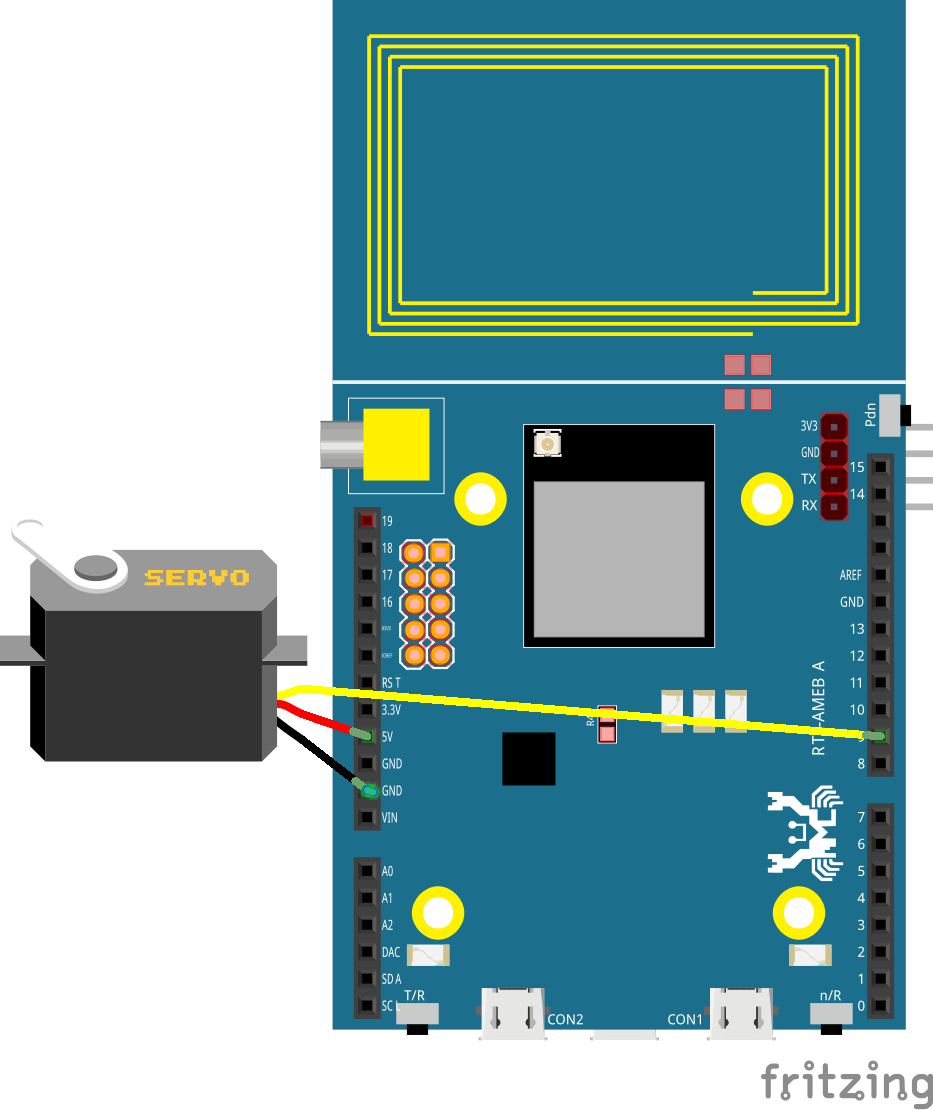
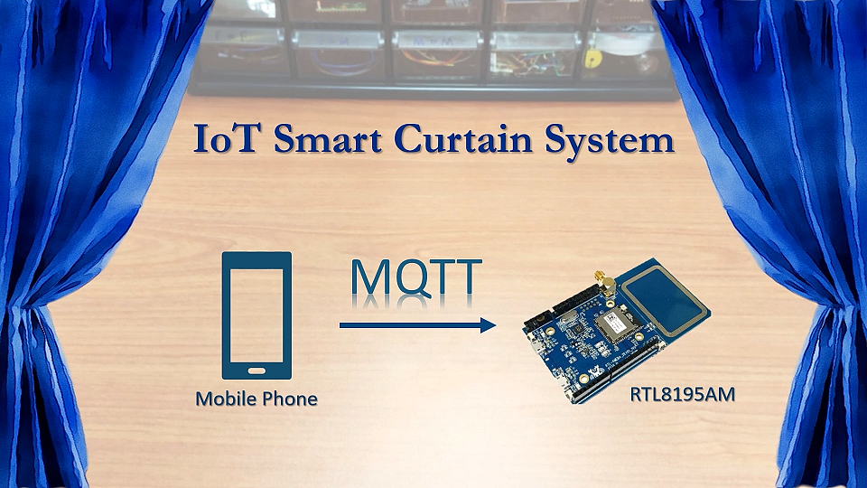
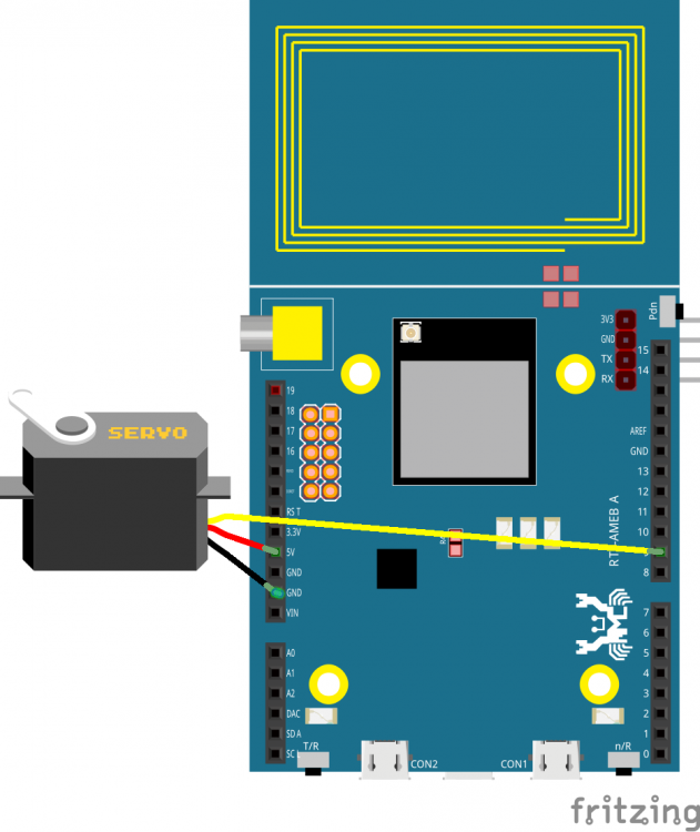
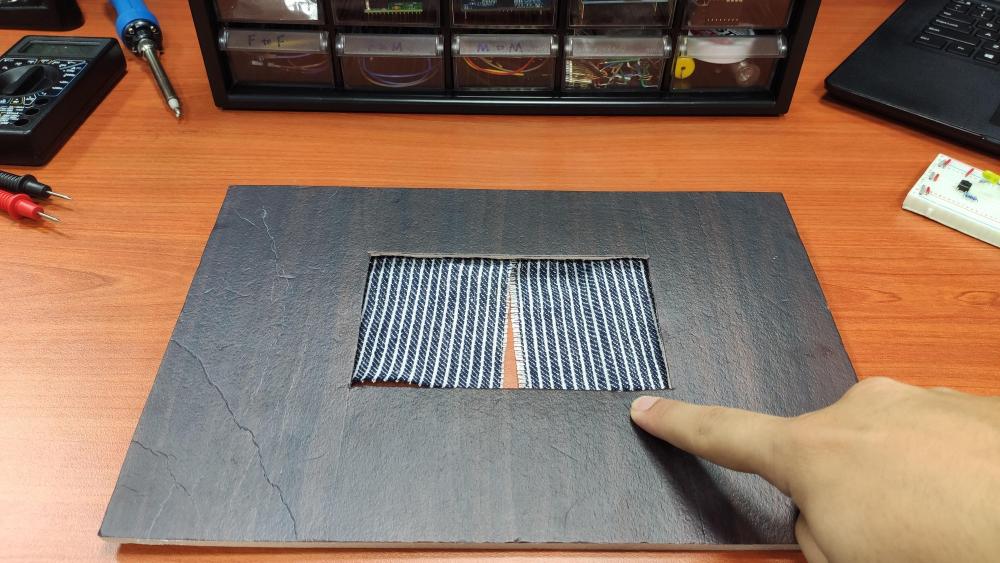
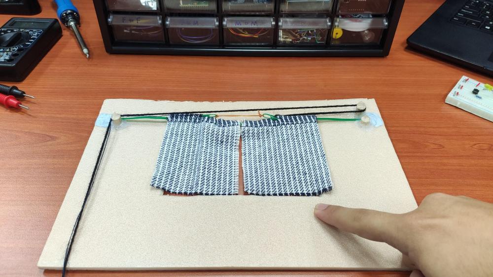
 The focus of this project is to demonstrates how easy it is for Ameba Wi-Fi Dev. board to communicate with our smart phone via MQTT protocol. Phone to microcontroller communication used to be very difficult as they use totally different hardware interface and phone get its data mainly through the network. Now with a Wi-Fi enabled microcontroller like Ameba RTL8195AM, communication with our phone becomes a bliss. Of course, in this video, only a mini window is used for demonstration purpose, but controlling a real window should not be a problem if you simply replace the servo motor with a bigger DC step motor and change the source code accordingly. With this smart curtain system, you may, 1. Remotely control your curtain to open or close instantaneously 2. Check your curtain status according to the MQTT message received 3. Link with the previous weather station project and automate your room from there GitHub page https://github.com/Realtek-AmebaApp/Ameba_Examples/tree/master/RTL8195AM/005_SMART_CURTAIN Official pages https://www.amebaiot.com.cn/en/ https://www.amebaiot.com/en/ Facebook pages https://www.facebook.com/groups/AmebaIoT/ BiliBili channel https://space.bilibili.com/45777743
-
Realtek's ameba dev. board is capable of USB OTG and SDIO thus making it possible to take photo with a UVC camera and store it in a SD card via SDIO. Here, combining these 2 function, one can easily create a Time Lapse Photography with merely an arduino size MCU. Here is a tutorial about it, Preparation Ameba x 1 SD card or MicroSD card x 1 SD sniffer x 1 (optional) Logitech C170 web cam x 1 Micro USB OTG adapter x 1 Example In this example, we use UVC to take photos and save to SD card at regular time, which is similar to time lapse photography. Open the sample code in "File" -> "Examples" -> "AmebaSdFatFs" -> "time_lapse_photography" In the sample code, we start the UVC at first, then initialize SD FAT FS. In loop(), use UVC to capture photo every three seconds, and the captured photos are numbered in 0001.jpeg, 0002.jpeg, 0003.jpeg, ... There are some tools to turn these photos to a video. We use ffmpeg here: https://ffmpeg.org/ In Windows OS environment, type the command in the directory of all UVC photos: ffmpeg -framerate 30 -i %04d.jpeg -vf fps=30 -pix_fmt yuv420p output.mp4 The explanation of the arguments in the command: -framrate: By specifying this argument, you tell ffmpeg to use the time handled by framerate to be the timeline. Here we use 30, which means in 30 photos are displayed per second. -i: use this argument to specify input file name. We use "%04d.jpeg" to tell ffmpeg to read the files from 0000.jpeg, 0001.jpeg, 0002.jpeg, ... fps: the framerate of output video, we use 30 frames per second here. The last argument is the output file name. Demo video: Code reference The sample code is comprised of two parts: use UVC to capture photo, and write file to SD card. The UVC part please refer to previous "UVC – Use UVC To Send Image" example. And SD part please refer tp the "SDIO – Edit Files In SD Card" example
-
LoRa is a low-power wide-area network protocol developed by Semtech. It has a typical range of 10KM at low power consumption which is ideal in some IoT applicaitons. Using LoRa on Realtek's Ameba Dev. board is very easy, here is a tutorial about it, Materials Ameba x 1 Dragino LoRa Shield x 2 Example Dragino Lora Shield is a long range transceiver and based on Open source library. It allows the user to send data and reach extremely long ranges at low data-rates.It provides ultra-long range spread spectrum communication and high interference immunity whilst minimising current consumption. Due to different frequency regulations on each country, please notice the frquency LoRa Shield used when you purchase it. Download the LoRa Library: https://github.com/ambiot/amb1_arduino/raw/master/Arduino_libraries/AmebaLoRa.zip Refer to the documentation on Arduino website to install library and add the .zip file to Ameba: https://www.arduino.cc/en/Guide/Libraries#toc4 Dragino LoRa Shield SPI example wiring explanation: Dragino LoRa Shield can be embedded on Ameba board directly, but the Ameba CS pin is different to the standard SPI protocol. Therefore, Dragino LoRa Shield CS pin cannot connect to Ameba CS pin directly. Modify and pull the CS pin which is pin 10 toward inside and connect to pin 0 with dupont line on Dragino LoRa Shield. The example is shown below: Dragino LoRa Shield SPI Data is produced from ICSP SPI BUS, then connect to AMEBA SPI pin as follows: Below is the RTL8710 Wiring Diagram: Example Illustration This example uses send and receive code to do the functional verification for two Dragino LoRa Shield. One is for sender and another one is fr receiver. Open “File” -> “Examples” -> “AmebaLoRa” -> “LoRaSender” and LoRaReceiverCallback. Compile them separately and upload to Ameba, push the Reset button. Then you can see the results on the terminal:
-
A BLE beacon broadcasts its identity to nearby Bluetooth devices, to enable the other devices to determine their location relative to the beacon, and to perform actions based on information broadcast by the beacon. Example applications of beacons include indoor positioning system, location-based advertising and more. From the definition of its purpose as a broadcast device, a BLE beacon thus cannot be connected to, and can only send information in its Bluetooth advertisement packets. There are several BLE beacon protocols. The Ameba BLEBeacon library supports the iBeacon and AltBeacon protocols.

-
BLE connections use a server client model. The server contains the data of interest, while the client connects to the server to read the data. Commonly, a Bluetooth peripheral device acts as a server, while a Bluetooth central device acts as a client. Servers can contain many services, with each service containing a some set of data. Clients can send requests to read or write some data and can also subscribe to notifications so that the server can send data updates to a client. In this example, a basic battery service is set up on the Ameba Bluetooth stack. A mobile phone is used to connect the the Ameba peripheral device and read the battery data. GitHub page https://github.com/Realtek-AmebaApp/ Official pages https://www.amebaiot.com/en/ Facebook pages https://www.facebook.com/groups/AmebaIoT/
-
Ameba RTL8195AM has onboard NFC tag and run on ARM Cortex-M3 core with WiFi, just nice to make use of all these 3 powerful tool to make an useful applicaiton. Many models of Android smart phone support NFC feature, and numerous of NFC applications are developed for inspection and modification of NFC Tag. In this example, we establish NFC connection between Ameba and a smartphone, and open a webpage on the smartphone via a NFC event. Preparation Ameba x 1 Smartphone with NFC feature x 1 Note: Make sure the onboard NFC antenna is safely connected to the module. Then open the example, "File" -> "Examples" -> "AmebaNFC" -> "UriWebPage" and upload, you will see this message when you tap your NFC-enabled phone on Ameba For more details, refer to the offical website at https://www.amebaiot.com/en/ameba-arduino-nfc-open-web/ Also feel free to join the Facebook group to discuss with other makers! https://www.facebook.com/groups/AmebaIoT
-
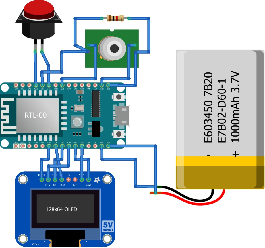
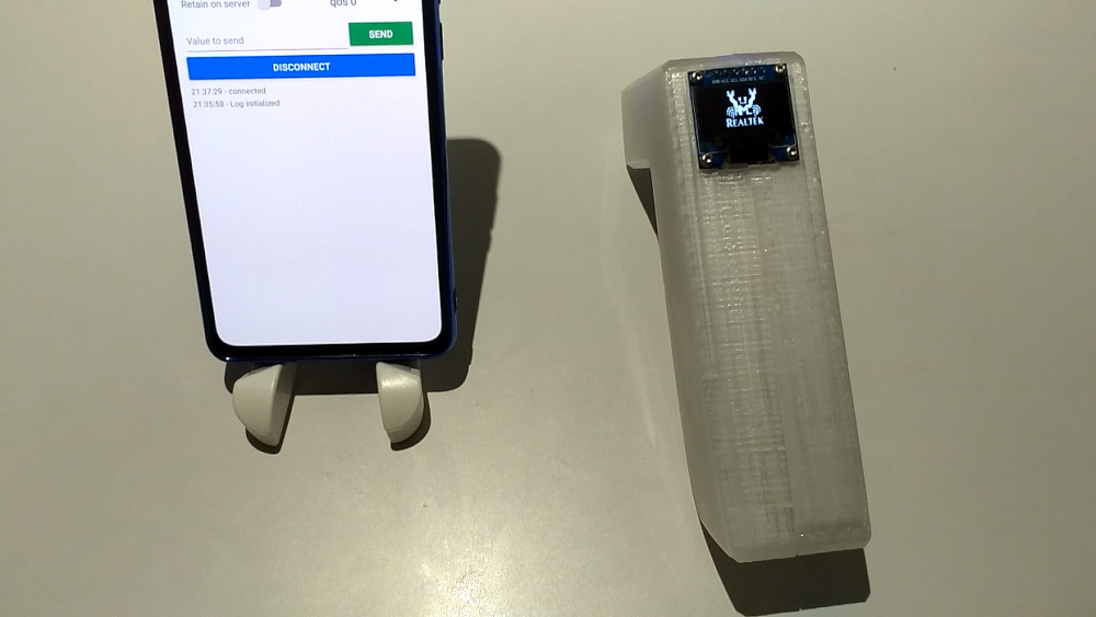
With COVID-19 still wreaking havoc globally, causing thousands of deaths, millions hospitalized, any useful medical device is on high demand, especially household medical device like IR non-contact thermometer. Handheld thermometer usually is on high price point and is hard to come by these days, but the components needed to make thermometer are not that expensive, that give us the perfect reason to DIY one during this lockdown period. This ThermoGun project use Ameba Dev. board RTL8710AF from Realtek, which connects to an OLED display to show temperature data obtained from the MLX90615 IR sensor. Pushing the push button not only perform data acquisition and visualization, but also publish the data via MQTT to all subscribers. Note: The MQTT service used in this project is a FREE MQTT broker hosted at cloud.amebaiot.com, which need to register at www.amebaiot.com . Details of registration is at the link below, https://www.amebaiot.com/en/cloud-getting-started/ For details of step-by-step guide and connections, please refer to Github page here, https://github.com/Realtek-AmebaApp/Ameba_Examples/tree/master/RTL8195AM/007_THERMOGUN Demo Video: https://youtu.be/Yl3arBRmyYI
-
Realtek Ameba RTL8195 - Thermometer
Michael Zhang posted a topic in Electronic Projects Design/Ideas
This project use Ameba Dev. board RTL8710AF, which connects to an OLED display to show temperature data obtained from the MLX90615 IR sensor. Pushing the push button not only perform data acquisition and visualization, but also publish the data via MQTT to all subscribers. The casing is using 3D printing all 3D design files will be open source on github page. GitHub page https://github.com/Realtek-AmebaApp/ Official pages https://www.amebaiot.com/en/ Facebook pages https://www.facebook.com/groups/AmebaIoT/
-
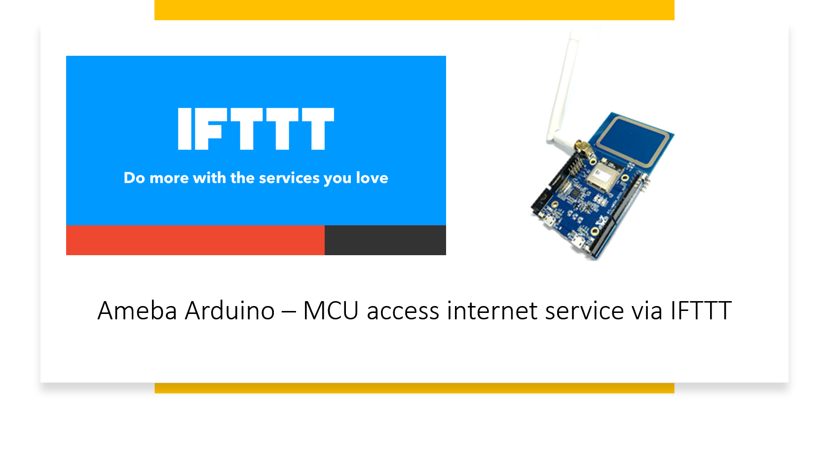
Accessing internet service is an easy job for a smart device like an android phone, tablet or a PC, but not so easy on microcontrollers since it usually requires better connectivity and processing power. However, we may offload the heavy part of the job to IFTTT to help us accomplish a great variety of internet service with ease. This tutorial will show you how to make use of IFTTT to do just that. Introduction to IFTTT IFTTT, known as If This Then That, is a website and mobile app and free web-based service to create the applets, or the chains of simple conditional statements. The applet is triggered by changes that occur within other web services such as Gmail, Facebook, Telegram, Instagram, Pinterest etc. Preparation Ameba x 1 An account from https://ifttt.com/ , in order to access IFTTT service* For detailed step-by-step guide, you may refer to link below, https://www.amebaiot.com/en/ifttt-via-ameba/

-
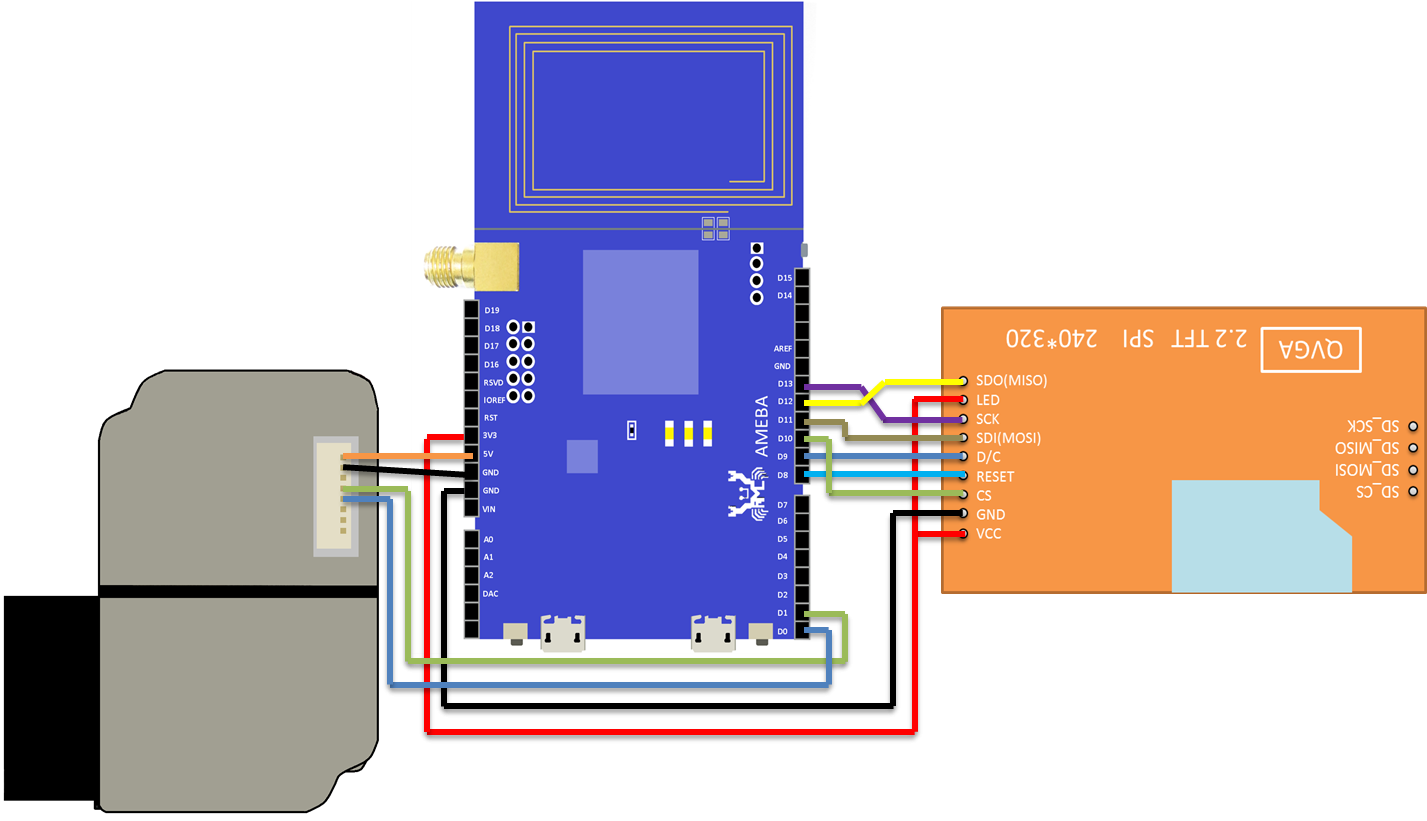
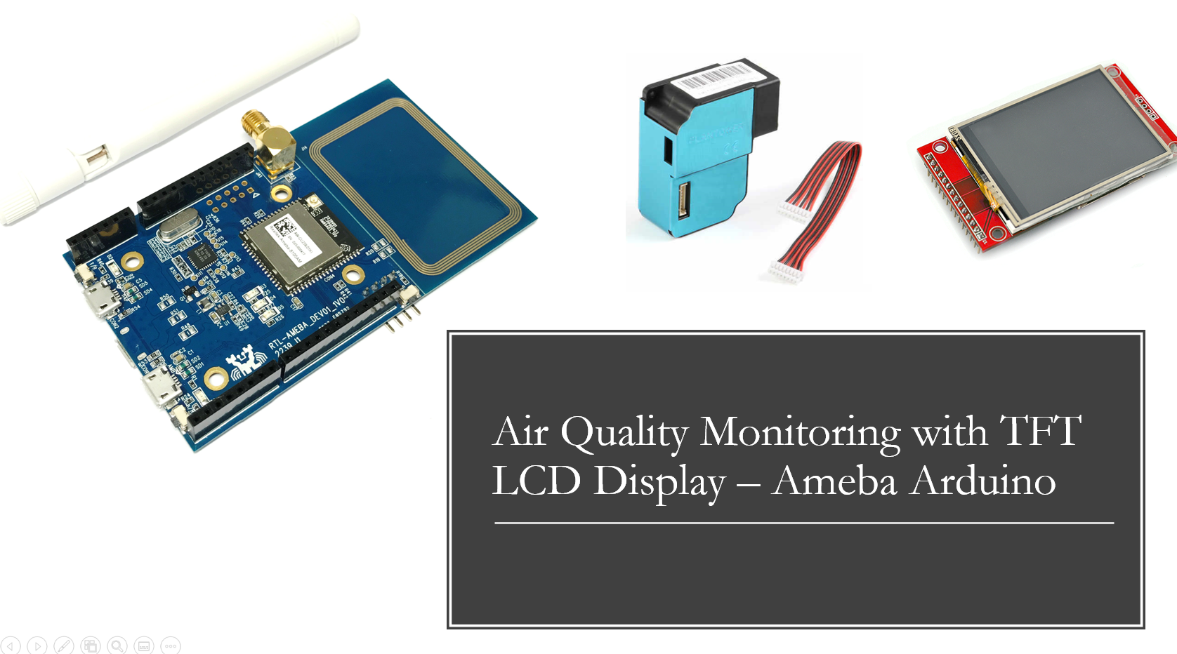
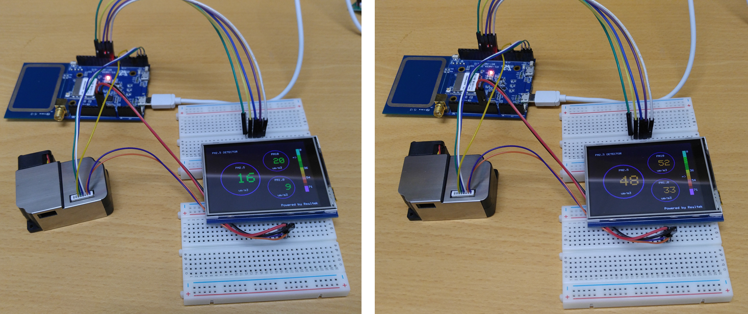
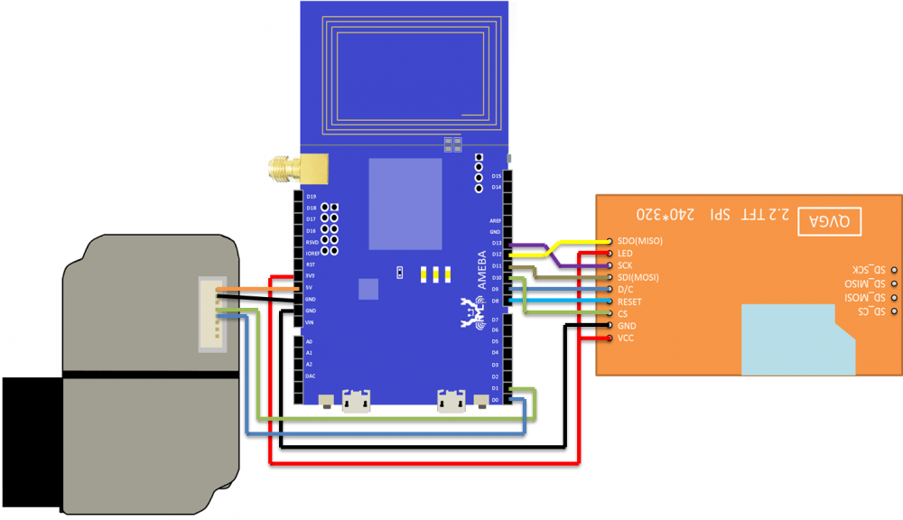
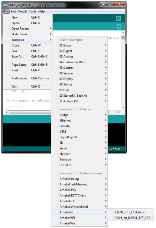
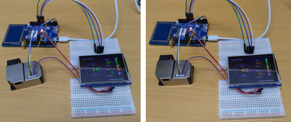
Now that most people stay at home to avoid close contact with potential COVID-19 virus carrier, air quality becomes an important factor to people’s well-being, especially in tropical countries where using air-con is a must during the day, as prolonged use of air-con may do more bad than good to people’s respiration system thus weakening our immunity and make people more susceptible to virus infection. Here I am going to show you how to make a simple yet powerful air quality monitoring system using Realtek Ameba RTL8195AM development board and PM2.5 module, together with a TFT LCD display to create a colourful interface. Preparation § Ameba x 1 § ILI9341 TFT LCD with SPI interface x 1 § Plantower PMS3003 or PMS5003 x 1 Example This example extends previous PM2.5 example to show the PM2.5 concentration on the LCD. Wiring of QVGA TFT LCD: (Note: PMS3003/PMS5003 sensor requires 5V voltage) Open the example, "Files" -> "Examples" -> "AmebaSPI" -> "PM25_on_ILI9341_TFT_LCD" Compile and upload to Ameba, then press the reset button. Then you can see the concentration value of PM1.0, PM2.5 and PM10 on the LCD. Code Reference In this example, first rotate the screen by 90 degrees, and draw the static components such as the circles, the measuring scale and the title text. After the concentration value is detected, it is printed inside the circle. To know more about the details, click the link below, https://www.amebaiot.com/en/ameba-arduino-spi-lcd-pm2-5/

-
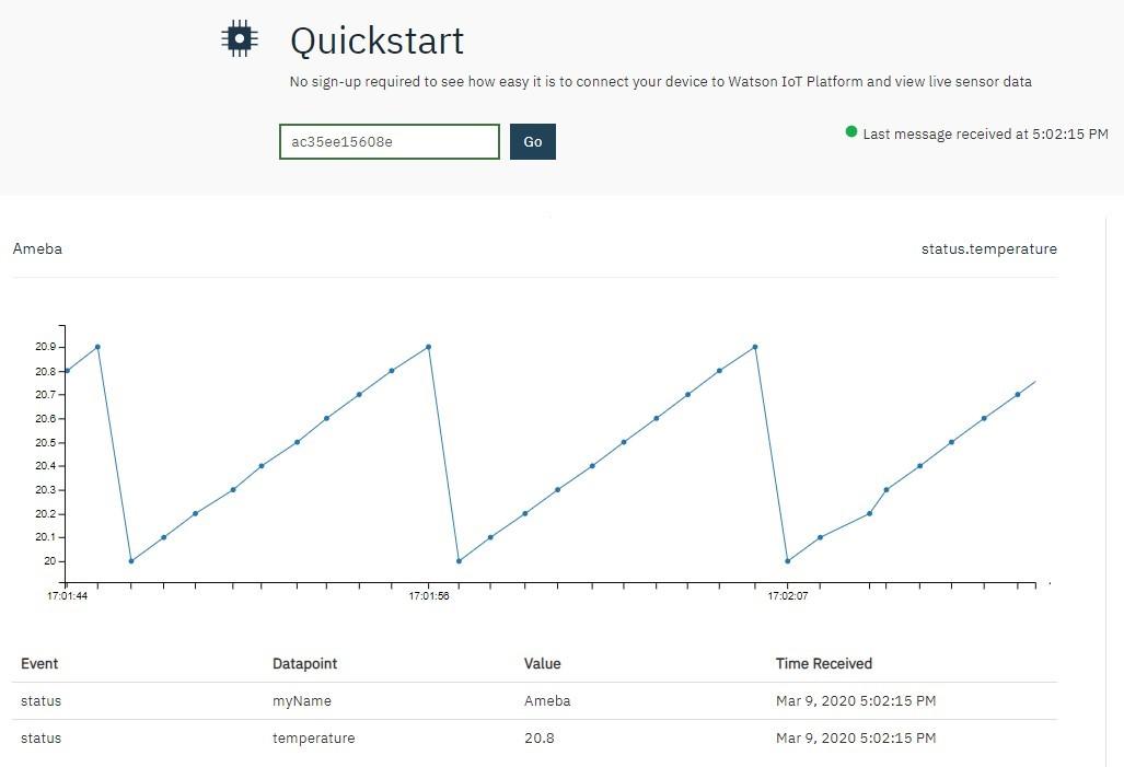
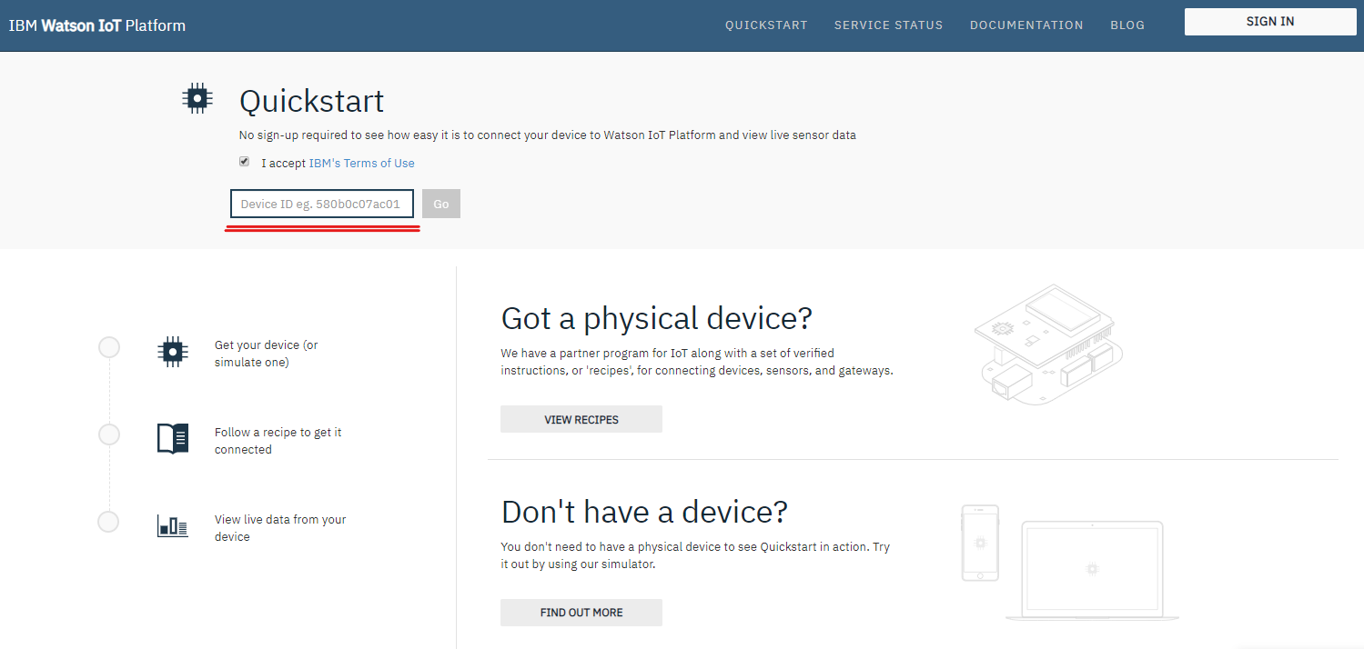
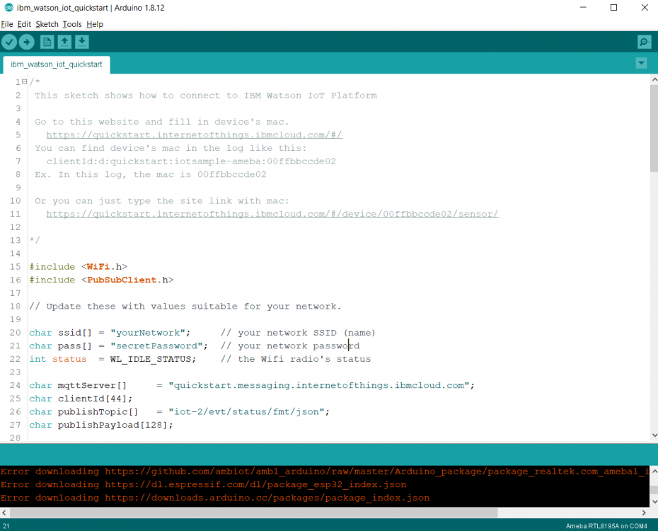
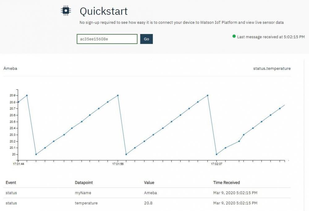
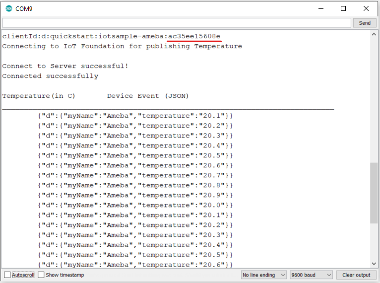
MQTT (Message Queuing Telemetry Transport) is a protocol proposed by IBM and Eurotech. IBM® Watson™ IoT Platform is, by the official definition, “A foundational cloud offering that can connect and control IoT sensors, appliances, homes, and industries. Built on IBM Cloud, Watson IoT Platform provides an extensive set of built-in and add-on tools. Use these tools to process IoT data with real-time and historical analytics, extract key performance indicators (KPIs) from your data, add “smarts” in the cloud for non-smart products, and securely connect your own apps and existing tools to the Watson IoT Platform infrastructure.” (IBM, 2020) This platform provides easy web interface to register, connect and visualize our IOT devices. For quick start and simple try-out, registration is not necessary, we may just run our program to get the device ID needed for this platform. Preparation § Ameba x 1 Example In this example, we will take a look at how to make use of IBM Watson IOT platform for out IOT project. Open the MQTT example “File” -> “Examples” -> “AmebaMQTTClient” -> “ibm_watson_iot_quickstart” Make sure the Wi-Fi information is properly filled in and we are ready to upload the code to ameba. Once uploading finished, open a serial monitor and we shall see information as follows, Important: Please take note of the string of characters on the first line of the picture above -- “clientId:quickstart:iotsample-ameba:ac35ee15608e” “ac35ee15608e” is the device ID as well as the MAC address of the ameba board used here which will NOT be the same for other cases, so make sure to copy down the device ID displayed on your serial monitor. Next, we click the IBM IOT platform link provided here and open our browser: https://quickstart.internetofthings.ibmcloud.com/#/ Paste the device ID we just copied into the box highlighted below, If the device ID keyed in is correct, some fake temperature data that our ameba published will be visualized like this, Done! Now you have FREE and working IOT cloud platform to help you visualize your IOT data in realtime~


-
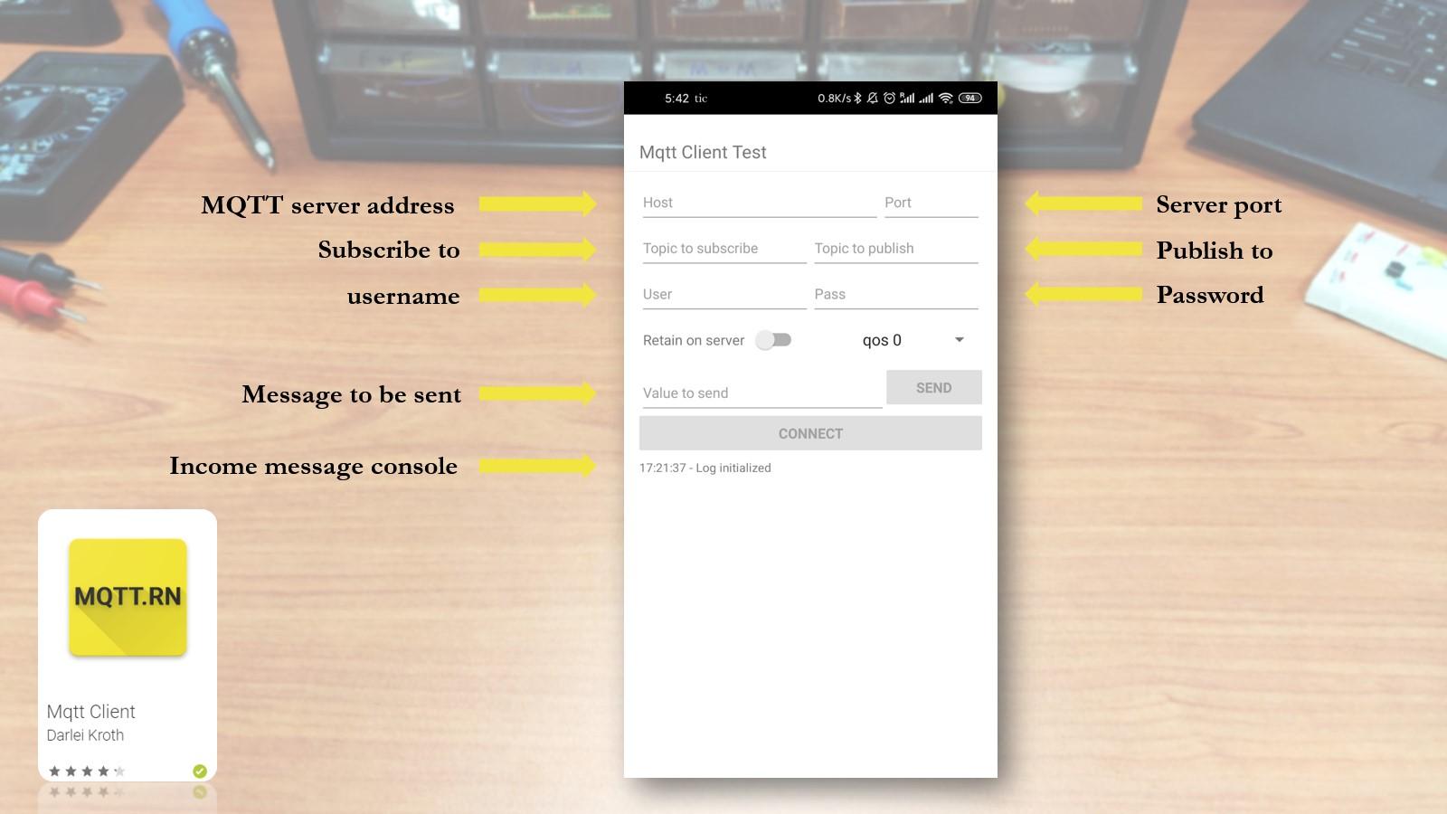
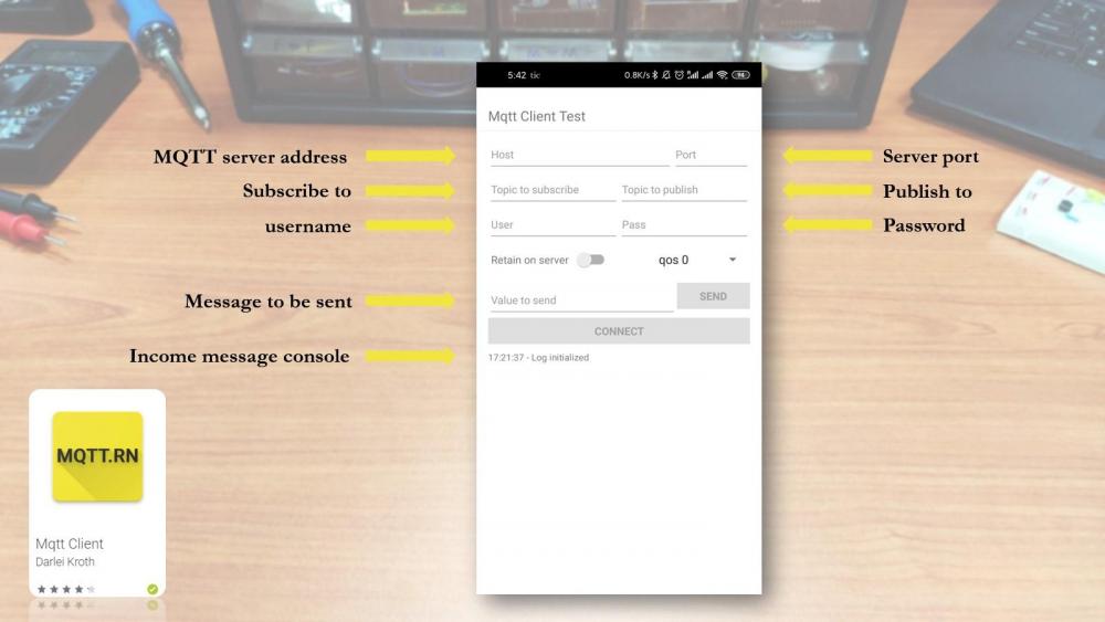
This project is the second one in the new IOT project series on Ameba RTL8195AM Dev. Board. The focus of this project is to demonstrates how easy it is for Ameba Wi-Fi Dev. board to communicate with our smart phone via MQTT protocol. Phone to microcontroller communication used to be very difficult as they use totally different hardware interface and phone get its data mainly through the network. Now with a Wi-Fi enabled microcontroller like Ameba RTL8195AM, communication with our phone becomes a bliss. Of course, in this project, only a mini hand-crafted window is used for demonstration purpose but controlling a real window should not be a problem if you simply replace the servo motor with a bigger DC step motor and change the source code accordingly. With this smart curtain system, you may, 1. Remotely control your curtain to open or close instantaneously 2. Check your curtain status according to the MQTT message received 3. Link with the previous weather station project and automate your room from there Hardware List of hardware needed Ameba 1 RTL8195AM x1 Servo motor x1 Jumper wires x3 DIY materials x3 Hardware connection is shown below, for the window, you may use a Lego house as substitute or simply build one using plywood or hard form board, the exact structure can also be found in this folder. Software 1. Check and make sure you have installed the ameba 1 board to Arduino IDE via adding this link into “additional boards manager URLs” under “Preference”, and install it in “board manager” under “Tools”, https://github.com/ambiot/amb1_arduino/raw/master/Arduino_package/package_realtek.com_ameba1_index.json 2. Upload source code to your Ameba1 RTL8195 board using arduino IDE 3. Install a MQTT client App on your smart device (android/iOS) a) To use a MQTT service, you must first get a free MQTT server address b) Go to www.amebaiot.com and register for a user c) Then go to cloud service tab and register your device d) Once approved, the same username and password used for registration can be used to make use of the MQTT service for free 4. Connect to your MQTT server by keying in the correct server address, port number, username and password • For Host name: cloud.amebaiot.com • For Port number: 1883 • For username: same as your amebaiot.com username • For password: same as your amebaiot.com password 5. Key in the topics that you specified in the code, always remember to swap the publish topic and subscribe topic when you want to monitor your microcontroller’s published data.
-
The project demonstrates how an IoT device (Ameba RTL8195) is applied in real-life scenarios. If you have watched previous demo videos, you should have no problem understanding how an LCD display, a DHT Temperature Humidity sensor and our Ameba RTL8195. It can be put together to form a fully functional smart weather station. Simply follow the instructions in our examples as follows to DIY your own weather station, 1. LCD 24H Clock https://www.electronics-lab.com/community/index.php?/topic/47704-realtek-ameba-rtl8195-lcd-24h-clock/ 2. MQTT https://www.electronics-lab.com/community/index.php?/topic/47715-realtek-ameba-rtl8195-mqtt-demo/ 3. DHT+MQTT https://www.electronics-lab.com/community/index.php?/topic/47735-realtek-ameba-rtl8195-iot-system-with-dht-mqtt/ The key to integrate these 3 examples successfully is to make sure that you have set up your MQTT server correctly and note that here we are using a different set of MQTT topics, namely “dht_data” and “dht_status”. Also, when connect DHT sensor, D13 pin is used as data input pin. GitHub page https://github.com/Realtek-AmebaApp/Ameba_Examples/tree/master/RTL8195AM/004_WEATHER_STATION Official pages https://www.amebaiot.com.cn/en/ https://www.amebaiot.com/en/ Facebook pages https://www.facebook.com/groups/AmebaIoT/ BiliBili channel https://space.bilibili.com/45777743
-
MQTT is a machine-to-machine (M2M)/"Internet of Things" (IOT) connectivity protocol. It was designed as an extremely lightweight publish/subscribe messaging transport. With an Arduino-compatible wireless soc, e.g. Realtek Ameba1 (RTL8195/RTL8710) dev. Board, we can create a MQTT client that sends our sensor data to the cloud or any other MQTT clients. The source code is available on github at, https://github.com/ambiot/amb1_arduino/blob/master/Arduino_package/hardware/libraries/MQTTClient/examples/mqtt_basic/mqtt_basic.ino The things that need to take note of, · The "mqttServer" refers to the MQTT-Broker, we use the MQTT sandbox "test.mosquitto.org", it is provided by IBM eclipse for developers to test MQTT. · "clientId" is an identifier for MQTT-Broker to identify the connected device. · "publishTopic" is the topic of the published message, we use "outTopic" in the example. The devices subscribe to "outTopic" will receive the message. · "publishPayload" is the content to be published. · "subscribeTopic" is to tell MQTT-broker which topic we want to subscribe to. Here we can use a chrome plugin "MQTTLens" to be a second MQTT client. You can find it in Chrome Web Store at, https://chrome.google.com/webstore/detail/mq-tt-lens-the-best/cgmogjdjpnemdlijokkdomfapcodiohh?utm_source=chrome-ntp-icon After setting up a “connection” and key in the same topics we used on Ameba, we should be able to see a “Hello World” message printed on the MQTT message console.
-
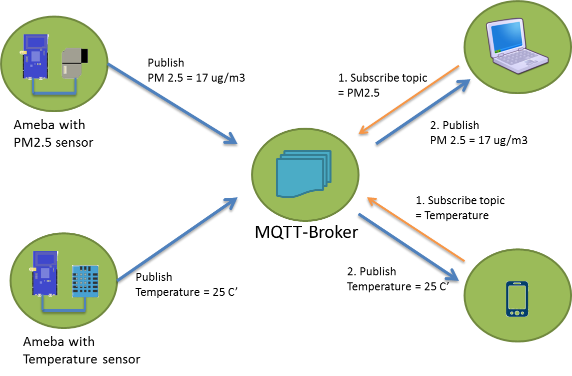
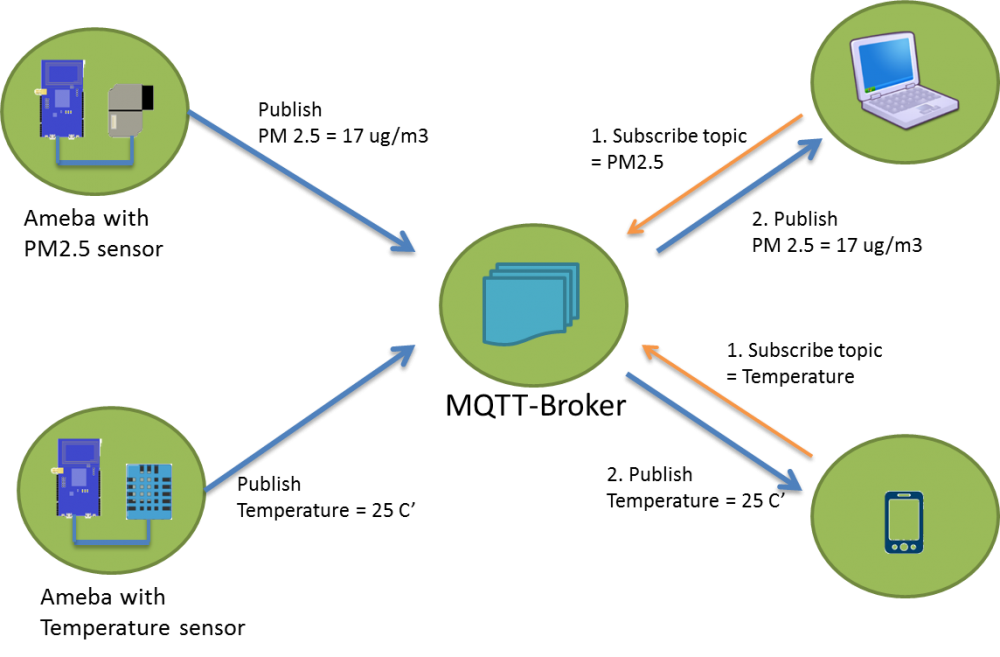
Temperature and humidity are 2 of the most important factors affecting people’s comfort level in an enclosed space. The DHT humidity and temperature sensor can read the ambient temperature and humidity every 2-3 seconds, and then pass the data to Ameba who will forward them to the server using MQTT protocol. Whoever “subscribing” to the right topic gets the data almost instantaneously. Users can then adjust the aircon mode or temperature according to the readings received. An android phone was used as an MQTT client and the Ameba RTL8195 Dev. Board acted as another MQTT client communicating with the android phone. Both clients have to connect to the same MQTT server before proceeding to the next step. The DHT sensor updates its data every 10 seconds to stay as accurate as possible. Once sensor data is received, Ameba then “publishes” the data to the MQTT server where all clients “subscribing” to the right topic gets the data displayed on the console. GitHub page https://github.com/Realtek-AmebaApp/Ameba_Examples/tree/master/RTL8195AM/003_DHT_MQTT Official pages https://www.amebaiot.com.cn/en/ https://www.amebaiot.com/en/ Facebook pages https://www.facebook.com/groups/AmebaIoT/ https://www.facebook.com/groups/AmebaIoTWW/ BiliBili channel https://space.bilibili.com/45777743
-
This is a simple IoT project based on the “mqtt basic” example that comes with the Arduino package when you install the RTL8195 on Arduino IDE. In this project, simple passive components are used to aid in demonstrating the power of bidirectional communication of MQTT protocol which is widely used in modern IoT applications for its advantages in speedy response and lightweight. In the video, an android tablet was used as a MQTT client and our Ameba RTL8195. Board acted as another MQTT client communicating with the android tablet. Both client have to connect to the same MQTT server before proceeding to the next step, you may choose to set up own MQTT server or using an online free server. Please refer to the video link, GitHub source code, https://github.com/Realtek-AmebaApp/Ameba_Examples/tree/master/RTL8195AM/002_MQTT_BASIC Official pages https://www.amebaiot.com.cn/en/ https://www.amebaiot.com/en/
-
We live in an age where IoT is a growing phenomenon, and therefore we often come across terms like LoRa and LoRaWAN. Most people use these terms interchangeably as they seem alike. However, this is not perfectly true as they have some differences. In this article, we will take a look at the pertaining differences between LoRa and LoRaWAN. We will also look at some of their prospective applications, and prominent benefits. Before understanding the key differences, we will have to develop a keen understanding of some essential terminologies. LoRaWAN + BLE Technology for Location Solution An indoor location system is formed by integrating wireless communication, base station and inertial navigation positioning, and other technologies to identify and monitor the position of persons and objects in an indoor space. Common indoor wireless positioning technologies include WiFi, Bluetooth, infrared, ultra-wideband, RFID, ultrasound and Zigbee. but they are not ideal for accurate, low-cost, low power and long-range indoor location systems. Based on new generation BLE positioning and LPWAN technologies, we can provide a perfect and low-cost wireless location solution for both indoor and outdoor use by combining our LoRaWAN GPS tracker, BLE probe and Beacon product within the location system. How it works Scenario 1: For indoor positioning only, combine the Beacon and BLE probe. The BLE probe is placed in a fixed and known position where it will scan the nearby Beacon and send its MAC address, RSSI and raw data to the server. The Beacon position can be acquired using the Pythagoras theorem when the three BLE probes receive the same MAC address at the same time. Scenario 2: For both indoor and outdoor positioning, combine the LoRaWAN GPS tracker and BLE probe. The LoRaWAN GPS Tracker supports both BLE and GPS locations. The GPS positioning can be used for outdoor situations. With indoor situations, the LoRaWAN GPS Tracker can serve as a BLE beacon that can be scanned by the nearby BLE probe, which will send the information to the LoRaWAN server. The MOKOSMART LoRaWAN GPS Tracker position can be acquired using the Pythagoras Theorem when the three BLE probes receive the same MAC address at the same time.