Search the Community
Showing results for tags 'led'.
Found 10 results
-
In this tutorial, you will learn how to create a web server with ESP32 that can control an LED from any device connected to the same WiFi network. You will use the Arduino IDE to program the ESP32 and the web browser to access the web server. What You Need To follow this tutorial, you need the following components: An ESP32 development board A USB cable to connect the ESP32 to the computer The Arduino IDE installed on your computer The ESP32 add-on for the Arduino IDE Get PCBs For Your Projects Manufactured You must check out PCBWAY for ordering PCBs online for cheap! You get 10 good-quality PCBs manufactured and shipped to your doorstep for cheap. You will also get a discount on shipping on your first order. Upload your Gerber files onto PCBWAY to get them manufactured with good quality and quick turnaround time. PCBWay now could provide a complete product solution, from design to enclosure production. Check out their online Gerber viewer function. With reward points, you can get free stuff from their gift shop. Also, check out this useful blog on PCBWay Plugin for KiCad from here. Using this plugin, you can directly order PCBs in just one click after completing your design in KiCad. How It Works The ESP32 will act as a web server that can serve HTML and CSS files to web clients (such as web browsers or smartphones). The web page will have a button that can send an HTTP request to the ESP32 to turn the LED on or off. The ESP32 will also handle the HTTP requests from the web clients and respond accordingly. For example, if the ESP32 receives a request to turn the LED on, it will set the GPIO pin connected to the LED to HIGH and send back a confirmation message. ESP32 Code The code for the ESP32 is also straightforward. You need to include the WiFi.h and ESPAsyncWebServer.h libraries, which are used to connect the ESP32 to the WiFi network and to create the web server. You also need to define the WiFi credentials, the GPIO pin for the LED, and the web server object. Then, you need to create a function to generate the HTML and CSS code for the web page, which will have a button to toggle the LED state. Next, you need to create a function to connect the ESP32 to the WiFi network and print the IP address to the serial monitor. You also need to create a function to handle the HTTP requests from the web clients and change the LED state accordingly. Finally, you need to initialize the LED pin, the WiFi connection, and the web server in the setup() function, and keep the web server running in the loop() function. The complete code is shown below: #include <WiFi.h> #include <ESPAsyncWebServer.h> // WiFi credentials #define WIFI_SSID "Your WiFi SSID" #define WIFI_PASSWORD "Your WiFi Password" // LED pin #define LED_PIN // Web server object AsyncWebServer server(80); // LED state int LED_state = LOW; // Function to generate the HTML and CSS code for the web page String getHTML() { String html = "<!DOCTYPE HTML>"; html += "<html>"; html += "<head>"; html += "<style>"; html += "body {background-color: #F0F0F0; font-family: Arial, Helvetica, sans-serif;}"; html += "h1 {color: #333333; text-align: center;}"; html += "button {width: 150px; height: 50px; font-size: 20px; margin: 10px;}"; html += "</style>"; html += "</head>"; html += "<body>"; html += "<h1>ESP32 Web Server</h1>"; html += "<p>LED state: <span style='color: red;'>"; if (LED_state == LOW) html += "OFF"; else html += "ON"; html += "</span></p>"; html += "<button onclick=\"window.location.href='/led/on'\">Turn ON</button>"; html += "<button onclick=\"window.location.href='/led/off'\">Turn OFF</button>"; html += "</body>"; html += "</html>"; return html; } // Function to connect to WiFi network void connectWiFi() { Serial.print("Connecting to WiFi..."); WiFi.begin(WIFI_SSID, WIFI_PASSWORD); while (WiFi.status() != WL_CONNECTED) { delay(500); Serial.print("."); } Serial.println(); Serial.println("WiFi connected"); Serial.println("IP address: "); Serial.println(WiFi.localIP()); } // Function to handle HTTP requests void handleRequest(AsyncWebServerRequest *request) { // Get the request path String path = request->url(); // Check if the request is to turn the LED on if (path == "/led/on") { // Set the LED pin to HIGH digitalWrite(LED_PIN, HIGH); // Update the LED state LED_state = HIGH; // Send a confirmation message request->send(200, "text/plain", "LED turned on"); } // Check if the request is to turn the LED off else if (path == "/led/off") { // Set the LED pin to LOW digitalWrite(LED_PIN, LOW); // Update the LED state LED_state = LOW; // Send a confirmation message request->send(200, "text/plain", "LED turned off"); } // Otherwise, send the web page else { // Get the HTML and CSS code String html = getHTML(); // Send the web page request->send(200, "text/html", html); } } void setup() { // Initialize the serial monitor Serial.begin(115200); // Initialize the LED pin pinMode(LED_PIN, OUTPUT); digitalWrite(LED_PIN, LED_state); // Connect to WiFi network connectWiFi(); // Start the web server server.onNotFound(handleRequest); server.begin(); } void loop() { // Nothing to do here } Testing the Web Server To test the web server, you need to upload the code to the ESP32 board and open the serial monitor. You should see the IP address of the ESP32, which is something like 192.168.1.8 Then, you need to open a web browser on your computer or smartphone and enter the IP address of the ESP32. You should see the web page with the button to control the LED. You can click the button to toggle the LED state and see the confirmation message on the web browser. Conclusion In this tutorial, you learned how to create a web server with ESP32 that can control an LED from any device connected to the same WiFi network. You learned how to use the WiFi.h and ESPAsyncWebServer.h libraries to connect the ESP32 to the WiFi network and to create the web server. You also learned how to generate the HTML and CSS code for the web page and how to handle the HTTP requests from the web clients. You can use this tutorial as a basis for your own projects that involve controlling GPIO pins or other devices with the ESP32 web server. You can also customize the web page design and functionality to suit your needs. I hope you enjoyed this tutorial and found it useful. If you have any questions or feedback, please let me know. 😊
-
If you are looking for a way to add some colorful and dynamic lighting effects to your Arduino projects, you might want to try using neo-pixel rings. Neo-pixel rings are circular arrays of RGB LEDs that can be controlled individually by a single data line. They are easy to use and can create amazing patterns and animations with Arduino code. In this article, I will show you how to integrate a pixel ring with Arduino Nano, a small and cheap microcontroller board that can be programmed to interact with various sensors and devices. You will learn how to wire the neo-pixel ring to the Arduino Nano, how to install and use the Adafruit Neo Pixel library, and how to code some basic lighting effects using the neo-pixel ring. By the end of this article, you can create your custom lighting effects using a neo-pixel ring and Arduino Nano. You will also be able to modify and customize the code according to your preferences and needs. Let’s get started! Get PCBs For Your Projects Manufactured You must check out PCBWAY for ordering PCBs online for cheap! You get 10 good-quality PCBs manufactured and shipped to your doorstep for cheap. You will also get a discount on shipping on your first order. Upload your Gerber files onto PCBWAY to get them manufactured with good quality and quick turnaround time. PCBWay now could provide a complete product solution, from design to enclosure production. Check out their online Gerber viewer function. With reward points, you can get free stuff from their gift shop. Also, check out this useful blog on PCBWay Plugin for KiCad from here. Using this plugin, you can directly order PCBs in just one click after completing your design in KiCad. Materials and tools: 8-bit neo-pixel ring Arduino nano Jumper wires Mini USB cable Adafruit Neo Pixel library for Arduino Wiring: Connect the IN pin of the neo-pixel ring to the D2 pin of the Arduino nano Connect the VCC pin of the neo-pixel ring to the +5V pin of the Arduino nano Connect the GND pin of the neo-pixel ring to the GND pin of the Arduino nano Programming: Once all the connections are made, open up the Arduino IDE and go to the Include library option. Then add the downloaded zip library that we have previously mentioned. Once the library installation is successful, you can see the neo pixel library examples in the examples sketch. Next, open up the strandtest_wheel sketch and change the pin to 2. Because we have connected our Neo pixel to the D2 pin of the Arduino. # include <Adafruit_NeoPixel.h> #ifdef __AVR__ #include <avr/power.h> #endif #define PIN 2 // Parameter 1 = number of pixels in strip // Parameter 2 = Arduino pin number (most are valid) // Parameter 3 = pixel type flags, add together as needed: // NEO_KHZ800 800 KHz bitstream (most NeoPixel products w/WS2812 LEDs) // NEO_KHZ400 400 KHz (classic 'v1' (not v2) FLORA pixels, WS2811 drivers) // NEO_GRB Pixels are wired for GRB bitstream (most NeoPixel products) // NEO_RGB Pixels are wired for RGB bitstream (v1 FLORA pixels, not v2) // NEO_RGBW Pixels are wired for RGBW bitstream (NeoPixel RGBW products) Adafruit_NeoPixel strip = Adafruit_NeoPixel(8, PIN, NEO_GRB + NEO_KHZ800); // IMPORTANT: To reduce NeoPixel burnout risk, add 1000 uF capacitor across // pixel power leads, add 300 - 500 Ohm resistor on first pixel's data input // and minimize distance between Arduino and first pixel. Avoid connecting // on a live circuit...if you must, connect GND first. void setup() { // This is for Trinket 5V 16MHz, you can remove these three lines if you are not using a Trinket #if defined (__AVR_ATtiny85__) if (F_CPU == 16000000) clock_prescale_set(clock_div_1); #endif // End of trinket special code strip.begin(); strip.setBrightness(100); strip.show(); // Initialize all pixels to 'off' } void loop() { // Some example procedures showing how to display to the pixels: colorWipe(strip.Color(255, 0, 0), 50); // Red colorWipe(strip.Color(0, 255, 0), 50); // Green colorWipe(strip.Color(0, 0, 255), 50); // Blue //colorWipe(strip.Color(0, 0, 0, 255), 50); // White RGBW // Send a theater pixel chase in... theaterChase(strip.Color(127, 127, 127), 50); // White theaterChase(strip.Color(127, 0, 0), 50); // Red theaterChase(strip.Color(0, 0, 127), 50); // Blue rainbow(20); rainbowCycle(20); theaterChaseRainbow(50); } // Fill the dots one after the other with a color void colorWipe(uint32_t c, uint8_t wait) { for(uint16_t i=0; i<strip.numPixels(); i++) { strip.setPixelColor(i, c); strip.show(); delay(wait); } } void rainbow(uint8_t wait) { uint16_t i, j; for(j=0; j<256; j++) { for(i=0; i<strip.numPixels(); i++) { strip.setPixelColor(i, Wheel((i+j) & 255)); } strip.show(); delay(wait); } } // Slightly different, this makes the rainbow equally distributed throughout void rainbowCycle(uint8_t wait) { uint16_t i, j; for(j=0; j<256*5; j++) { // 5 cycles of all colors on wheel for(i=0; i< strip.numPixels(); i++) { strip.setPixelColor(i, Wheel(((i * 256 / strip.numPixels()) + j) & 255)); } strip.show(); delay(wait); } } //Theatre-style crawling lights. void theaterChase(uint32_t c, uint8_t wait) { for (int j=0; j<10; j++) { //do 10 cycles of chasing for (int q=0; q < 3; q++) { for (uint16_t i=0; i < strip.numPixels(); i=i+3) { strip.setPixelColor(i+q, c); //turn every third pixel on } strip.show(); delay(wait); for (uint16_t i=0; i < strip.numPixels(); i=i+3) { strip.setPixelColor(i+q, 0); //turn every third pixel off } } } } //Theatre-style crawling lights with rainbow effect void theaterChaseRainbow(uint8_t wait) { for (int j=0; j < 256; j++) { // cycle all 256 colors in the wheel for (int q=0; q < 3; q++) { for (uint16_t i=0; i < strip.numPixels(); i=i+3) { strip.setPixelColor(i+q, Wheel( (i+j) % 255)); //turn every third pixel on } strip.show(); delay(wait); for (uint16_t i=0; i < strip.numPixels(); i=i+3) { strip.setPixelColor(i+q, 0); //turn every third pixel off } } } } // Input a value 0 to 255 to get a color value. // The colours are a transition r - g - b - back to r. uint32_t Wheel(byte WheelPos) { WheelPos = 255 - WheelPos; if(WheelPos < 85) { return strip.Color(255 - WheelPos * 3, 0, WheelPos * 3); } if(WheelPos < 170) { WheelPos -= 85; return strip.Color(0, WheelPos * 3, 255 - WheelPos * 3); } WheelPos -= 170; return strip.Color(WheelPos * 3, 255 - WheelPos * 3, 0); } Next, select the correct port and board. Here is the response. Conclusion: You have learned how to connect neo pixel ring with Arduino Nano and create some lighting effects using Arduino code, You can try different colors, patterns, and speeds for your animations by changing the code parameters. You can also use other types of neo-pixel products, such as strips, matrices, or jewels, for more variety and complexity.
-
 Story A NeoPixel ring controlled by a DHT11 sensor and an Arduino Nano can be a fascinating project that combines temperature sensing with visual feedback. This article will guide you through the process of building such a system. Materials Needed Arduino Nano DHT11 Temperature and Humidity Sensor Neo Pixel Ring Jumper Wires Get PCBs For Your Projects Manufactured You must check out PCBWAY for ordering PCBs online for cheap! You get 10 good-quality PCBs manufactured and shipped to your doorstep for cheap. You will also get a discount on shipping on your first order. Upload your Gerber files onto PCBWAY to get them manufactured with good quality and quick turnaround time. PCBWay now could provide a complete product solution, from design to enclosure production. Check out their online Gerber viewer function. With reward points, you can get free stuff from their gift shop. Also, check out this useful blog on PCBWay Plugin for KiCad from here. Using this plugin, you can directly order PCBs in just one click after completing your design in KiCad. Step 1: Connecting the Hardware First, connect the DHT11 sensor and the Neo Pixel ring to the Arduino Nano. The DHT11 sensor can be connected to any digital pin on the Arduino Nano. The Neo Pixel ring should be connected to the D2 pin of the Arduino Nano. Step 2: Installing the Libraries You will need to install the DHT library and the Adafruit Neo Pixel library in your Arduino IDE. These libraries contain the necessary functions to interact with the DHT11 sensor and the Neo Pixel ring. First Navigate to Sketch > Include Library > Manage Libraries... In the Library Manager, there is a search box. Type “DHT sensor library” into the search box. In the search results, find the library named “DHT sensor library” by Adafruit. Click on it, then click the “Install” button. And that’s it! You’ve successfully installed the DHT11 sensor library in Arduino IDE. This library should now be available for inclusion in your sketches. Step 3: Programming the Arduino The next step is to program the Arduino Nano. The program should read the temperature from the DHT11 sensor and change the color of the Neo Pixel ring based on the temperature. For example, you could program the Neo Pixel ring to display a blue color when the temperature is below a certain threshold. A green color when the temperature is within a comfortable range, and a red color when the temperature is above a certain threshold. Step 4: Testing the System After programming the Arduino Nano, it’s time to test the system. Power up the Arduino and observe the color of the Neo Pixel ring. Try changing the temperature around the DHT11 sensor (for example, by blowing hot or cold air onto the sensor) and see if the color of the Neo Pixel ring changes accordingly. #include <Adafruit_NeoPixel.h> #include <Adafruit_Sensor.h> #include <DHT.h> #include <DHT_U.h> #define DHTTYPE DHT11 // DHT 11 #define DHTPIN 3 DHT_Unified dht(DHTPIN, DHTTYPE); #define PIN 2 // Neo Adafruit_NeoPixel strip = Adafruit_NeoPixel(8, PIN, NEO_GRB + NEO_KHZ800); void setup() { Serial.begin(115200); dht.begin(); sensor_t sensor; strip.begin(); strip.setBrightness(100); strip.show(); } void loop() { sensors_event_t event; dht.temperature().getEvent(&event); Serial.print(F("Temperature: ")); float temp1 = event.temperature; Serial.print(temp1); Serial.println(F("°C")); dht.humidity().getEvent(&event); Serial.print(F("Humidity: ")); float hum1 = event.relative_humidity; Serial.print(hum1); Serial.println(F("%")); if (temp1 >= 28 && temp1 < 31) { strip.clear(); // Set all pixel colors to 'off' for (int i = 0; i < 12; i++) { // For each pixel... strip.setPixelColor(i, strip.Color(0, 150, 0)); strip.show(); } } else if (temp1 < 28) { strip.clear(); for (int i = 0; i < 12; i++) { // For each pixel... strip.setPixelColor(i, strip.Color(0, 0, 150)); strip.show(); } } else { strip.clear(); for (int i = 0; i < 12; i++) { // For each pixel... strip.setPixelColor(i, strip.Color(150, 0, 0)); strip.show(); } } } Conclusion Building a DHT11-controlled Neo Pixel ring with an Arduino Nano is a fun and educational project combining temperature sensing and visual feedback. With this system, you can visually monitor the temperature in a room and get a sense of whether the temperature is within a comfortable range.
 -
 Good day, all 🙂 Recently, I have a system running at 62V max, 54V nominal based on voltage divider rule formula. I wanted to have a little alert LED, so I was thinking about using 10, 1kohm resistors, and adding the LED bewteen the 9th and 10th (or 1st and 2nd, if it matters), to get at most 6V and just a few mA. Is a better/easier way? Is this a really crappy way? Or is this a perfectly fine way? 😶 Voltage Divider Basic and Rule.pdf
 -
Hi, all I'm using a PCA9685 with a pinout board like Adafruit's. I'm trying to run a bunch of LEDs at 20 mA, and the chip is supposed to be able to source 10 mA and sink 25 mA. I understand that to have it Source, you connect the LED between the PWM and GND pins and to Sink you connect it between V+ and PWM. I've tried both ways and using a multimeter and a red LED I get 12.5 mA. Why is it not 25 in Sink? Also, why do I get 12.5 on Source mode as well? Is there anyone have ideas of it? if possible a simple explanation would be nice. Many thanks.☺️
-
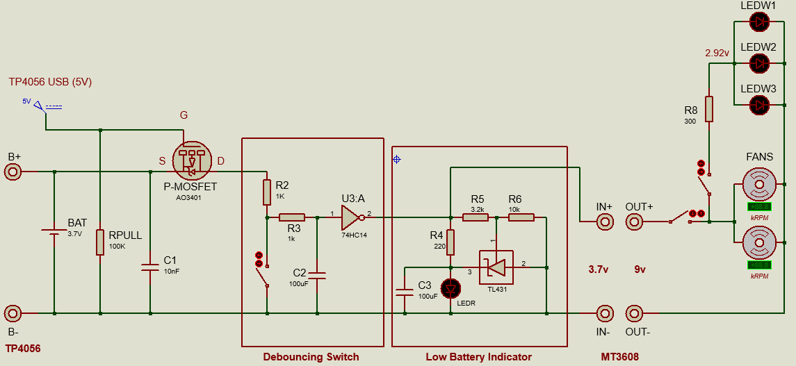
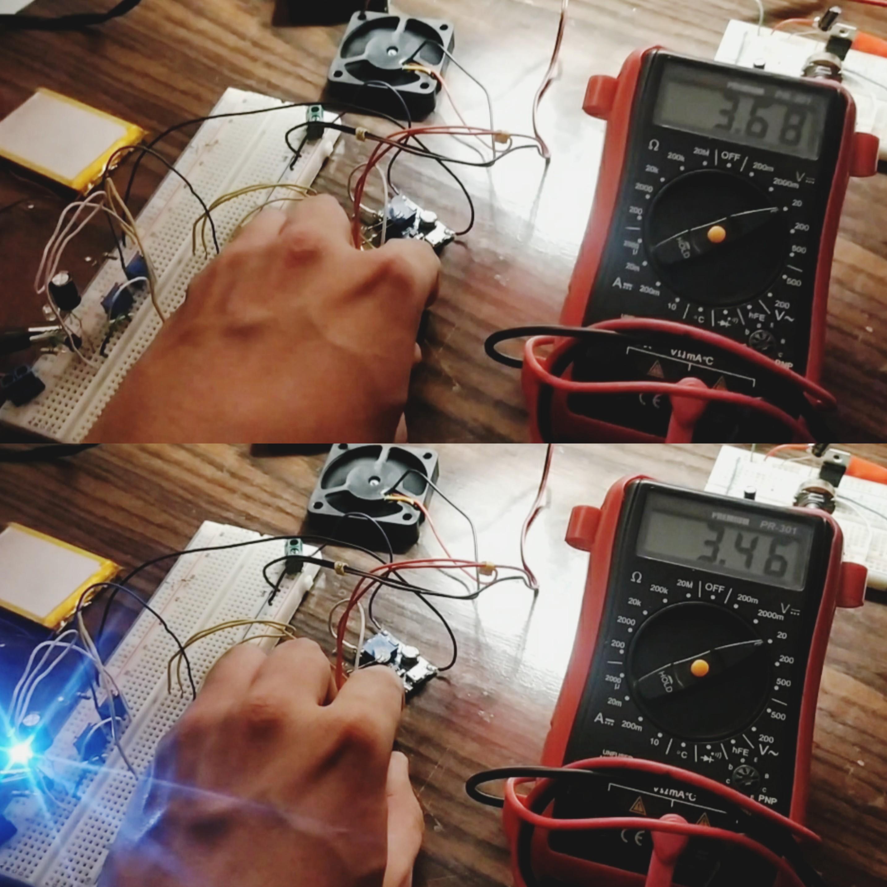
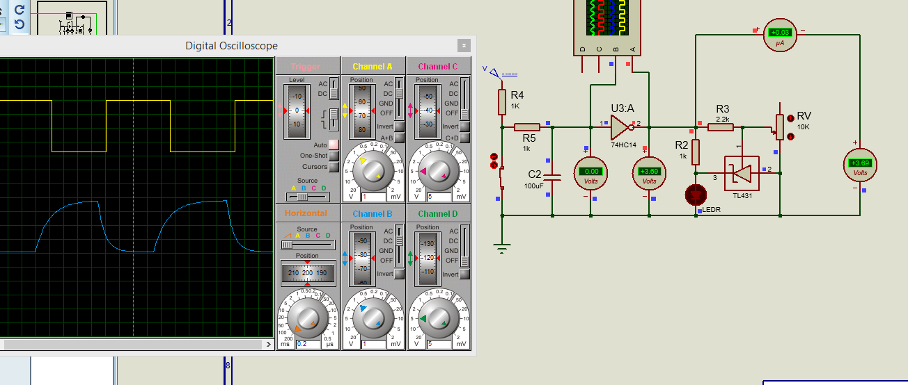
 Hi everyone. Can you help me with this circuit I am working on, please?. (Image 1) It consists of a TP4056 charger/controller connected to a 3.7v/1.4Ah Li-Ion battery to supply a low battery indicator and a load (3 leds + 2 fans) through a MT3608 Step Up to raise voltage from 3.7v to 9v. When the TP4056 is charging the battery through the USB port, the load is disconnected by the P-Mosfet. PROBLEM: Voltage drops significantly when the load is connected. Test1: Circuit without Debouncing/Load connected: Voltage drops from 3.68v to 3.46v (image 2). Low Battery Indicator: Blinks. Test2: Circuit with Debouncing/Load connected: 1) Debouncing Circuit: The voltage drops to 2.19v at the output of the Smichtt Trigger, therefore it isn't possible to energize the Step Up and the rest of the circuit. 2) Low Battery Indicator: Blinks when switch is pressed. Test3: Circuit with Debouncing/Load disconnected: 1) Debouncing Circuit: Works fine (image 3). 2) Low Battery Indicator: Doesn't blink when the switch is turned ON/OFF. Is there something that I am forgetting to put in the circuit so the voltage is dropping? I would suppose that the problem is at the DC/DC conversion of the Step Up, but everything is meeting its requirements (Vin:2v-24v/Imax: 2A). My system details: Power consumption: 1.702W Low Bat Indicator: (0.037W, 3.7v/0.01A) Load: 2 Fans (1.44W, 9v/0.16A), 3 Leds (0.059W, 2.92v/0.02A). Debouncing Circuit based on a Schmitt Trigger 74HC14 (Vin:2-6v/Vout:2-VCC, VCC and GND connected to battery line).
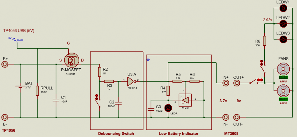


-
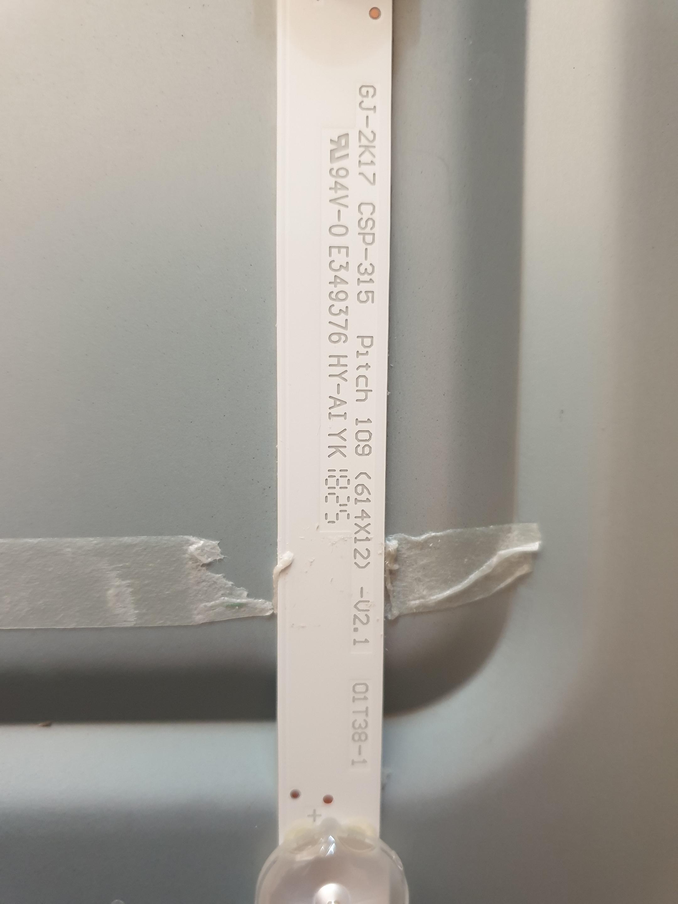
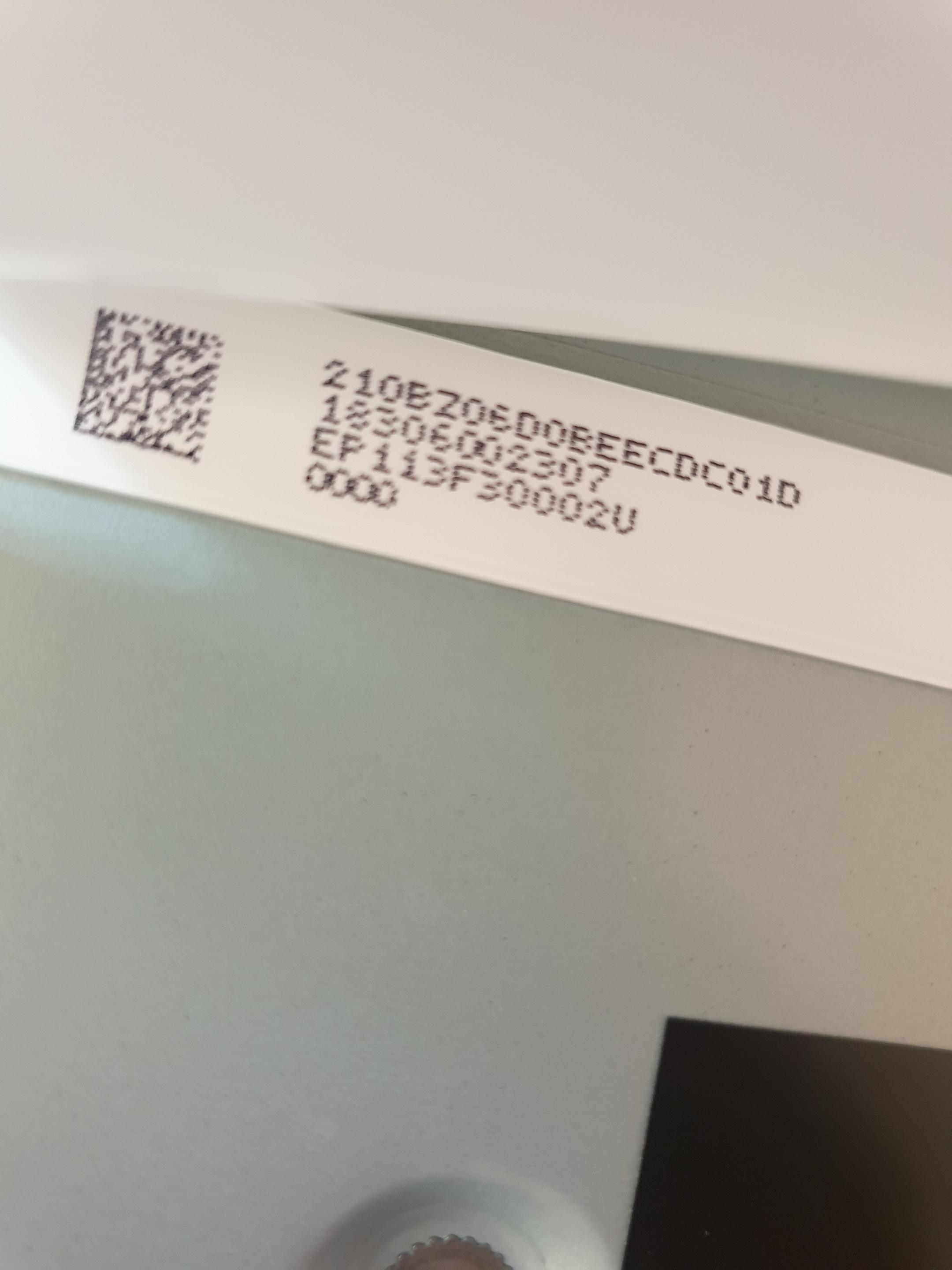
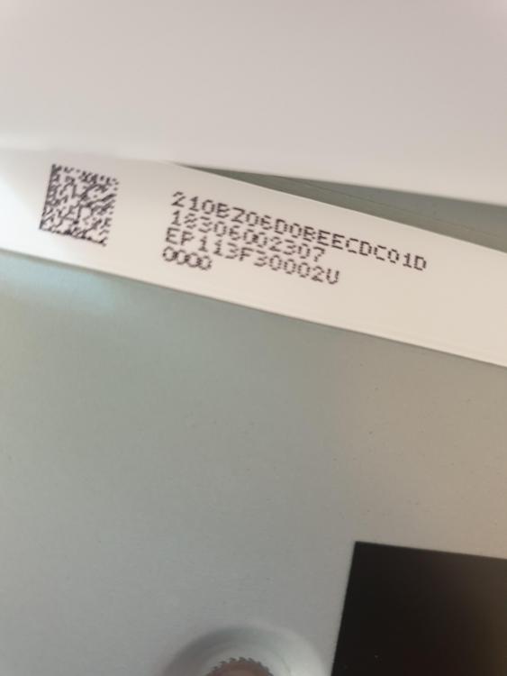
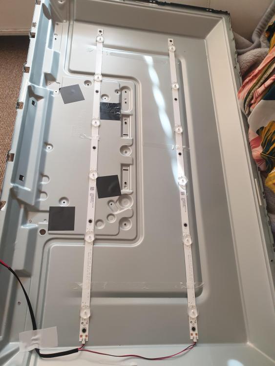
Hi everyone, newbie here! Trying to find a power supply for LED backlight strips off of an LCD television. I've stripped it down but can't see it marked clearly anywhere. There are 2 strips with 6 LEDs on each. Printed on the light strips is the following: GJ-2k17 CSP-315 Pitch 109 (614x12) -v2.1 O1T38-1 RJ94V-0 E349376 HY-AI YK 1825 Attached are photos Cheers for any help!
-
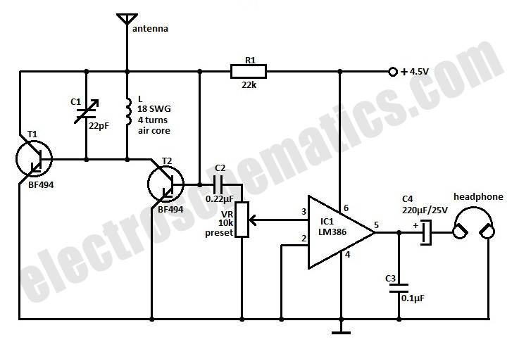
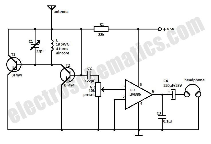
Hello, I am trying to modify an FM radio such that it blinks an LED according to the data I transmit from my FM transmitter. I am following the circuit attached below. Is it possible to connect LED to speaker terminals to obtain such result? or any other suggestions? Thanks
-
I want to charge a LiPo battery via the ballance plugs. So it's a ballanced charge, and I don't run into any problems, day in and day out.The light can be very small, but I want it to be bright. So even using a couple LEDs would make a really nice and bright mailbox light.I want the light to last all night long. So that means I need to know the current draw of the LEDs to the capacity of the LiPo batteries.etc.I need help on this. I need help with the fact how to use an Op Amp to shut the light off when it's daylight out.. or a specific amount of light is sensed.Light Sensed : Start charging, and turn off the LED lights.Light Sensed : Set the Op Amp to detect 4.2vdc. When it does, shut down the charging, &LED's stay off until darkness is detected.That's my idea of a mailbox light, with very long battery life, and high current solar charging abilities.Can anyone help me with this kind of circuit? Here is where my LED come from http://www.kynix.com/Search/led.html
-
How do I measure how many watt LED diode is on. Have some different that I do not know the value of.