


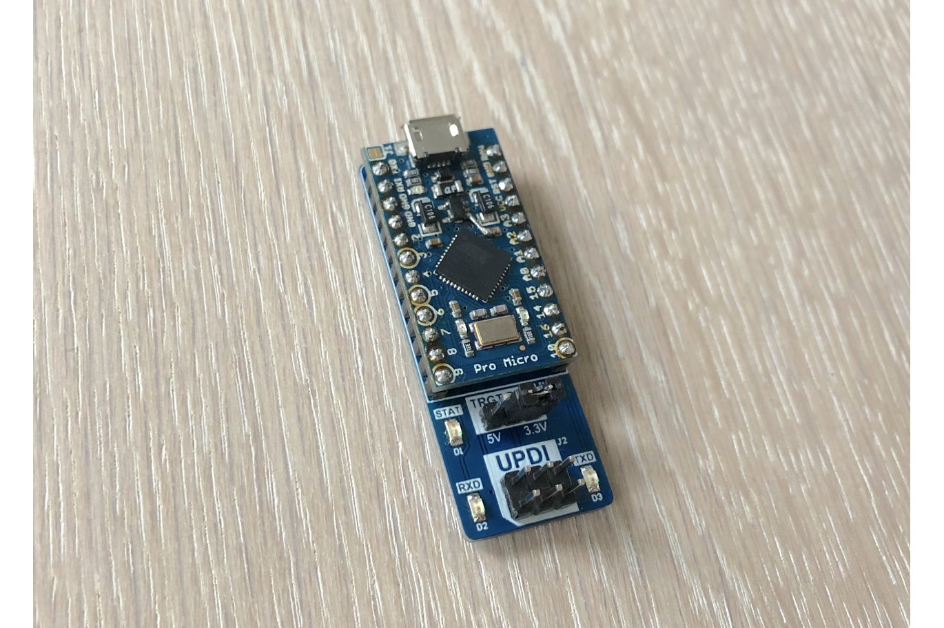
Thanks to the increased popularity of the recent ATtiny series of microcontrollers, there has been an increase in the number of open-source UPDI programmers out there. We have covered quite a number of them including the brilliant UPDI programmer compatible with Arduino IDE but we certainly have not seen the end of new designs. One of the latest interesting UPDI programmers we’ve seen is the project by Electronics Designer; Hans, which leveraged the capabilities of the Arduino Pro Micro 5v/16MHz, to create the simple, cheap, and easy-to-use programmer.
Some highlight features of the programmer as outlined by Hans include:
- A 6-pin UPDI programming connector
- UPDI interface for programming and debugging
- Serial interface for communicating with the target over UART
- Voltage selection jumper where you can choose between 5V, 3.3V or no target power
- RXD and TXD LEDs for visual feedback
- Buffered RXD and TXD lines for high impedance inputs and low impedance outputs
- Status LED
- Power up -> LED is briefly lid
- Normal operation -> LED is not lid
- Programming -> Activity indicator
- Small in size (18.3mm x 49.6mm)
Using the Arduino Pro Micro for the project comes with a cost as users may have to make a permanent modification to the board. In order to get the mEDBG firmware for the programmer to run properly, the AREF pin on the Arduino Pro Micro has to be connected to 5V. Sadly, this pin is not available as a physical pin, so users will have to locate it on the board and solder a tiny wire from the capacitor to pin 1 on the voltage regulator as shown in the image below.
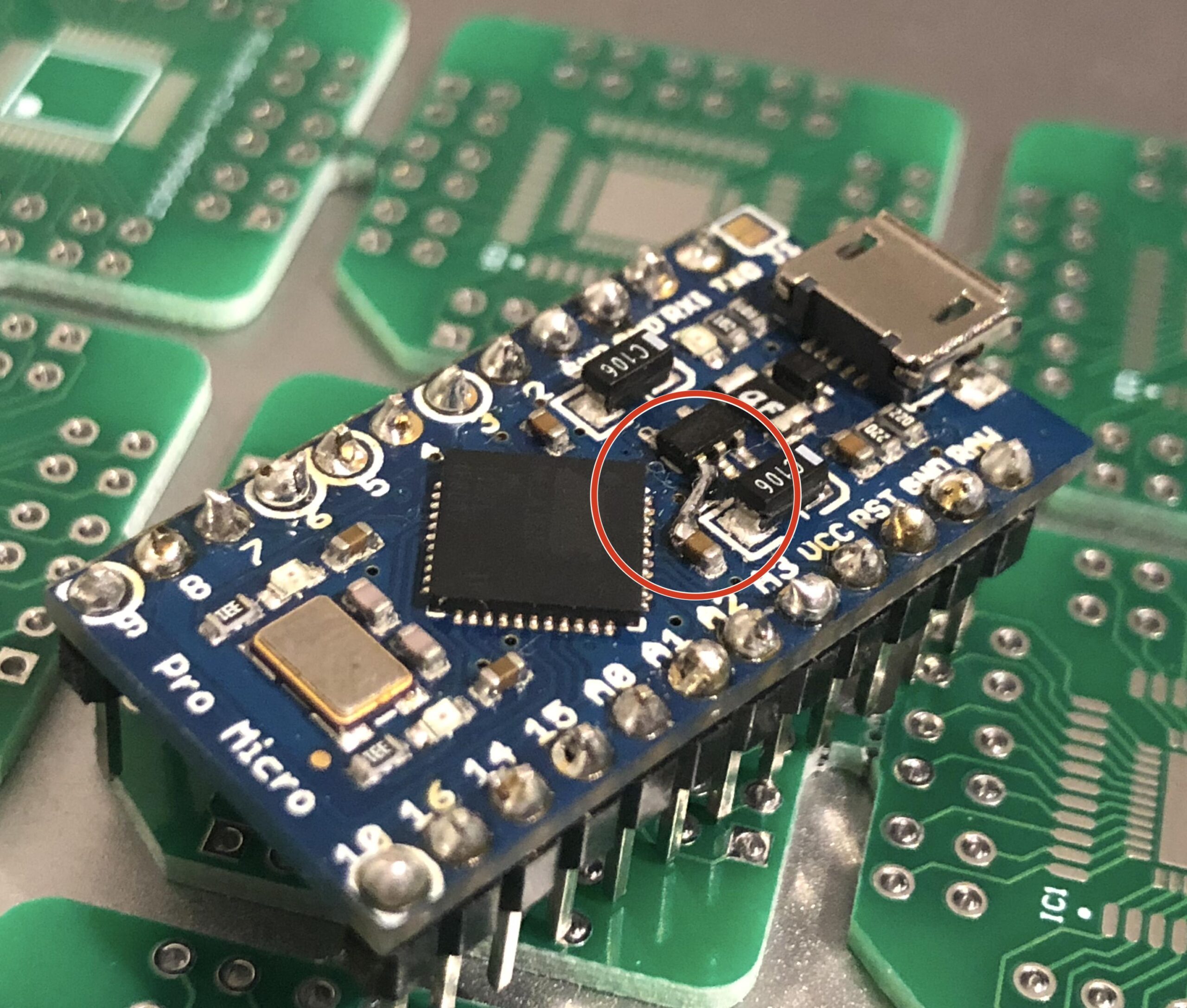
The consequence of this modification is that users will henceforth not be able to apply voltages higher than 5V to the Raw pin of the Arduino Pro Micro.
The device usage is quite straightforward. After flashing the Pro Micro with the mEDBG firmware, the device will henceforth present itself to the computer as an mEDBG CMSIS-DAP device. This will show up In Atmel Studio as a generic mEDBG device, and as the Arduino UNO WiFi Rev2 board on the Arduino IDE. To program the board with the megaTinyCore installed on the Arduino IDE, all you need do is to just select the Onboard Atmel mEDBG option in the Programmers menu and upload. However, for those who prefer the MegaCoreX, the programmer should be the Atmel mEDBG (microUPDI).
The project is entirely open source and all the design files including schematics, firmware, and build guides are available on the project’s GitHub repository. However, for users who will prefer to not deal with the hassles of making their own and just buy the board, it is available on Hans’s Tindie store for $13 excluding shipping.
More information on the project can be obtained on it’s Github Repo here
RELATED POSTS
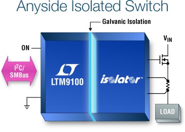 7 March, 2017 LTM9100 – Anyside™ High Voltage Isolated Switch Controller with I²C
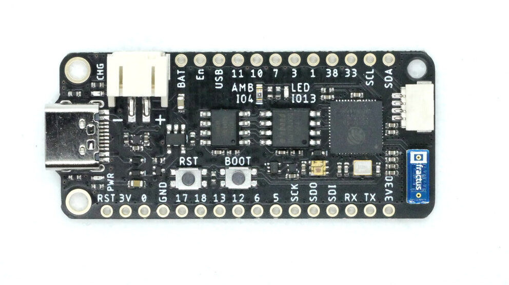 20 October, 2020 FeatherS2 – ESP32-S2 based development board in Adafruit Feather form factor
 4 March, 2024 Particle Announces M-Series – Multi-Radio Connectivity Solutions with BLE, Wi-Fi, LoRa, and Satellite Support
 20 October, 2022 ArduCam Brings Out New ToF Camera Module for Raspberry Pi
 31 October, 2023 Origami-Inspired Battery-Free Microfliers Revolutionize Environmental Monitoring
 16 August, 2022 Kneron KL720 AI SoCs


Why not take the 5v (4.85v) from VCC, that way you have the regulated voltage to AREF ??