

2 Channel Relay Board
- Rajkumar Sharma
- 30.812 Views
- easy
- Tested
- SKU: EL34772
- Quote Now
- 0 Likes

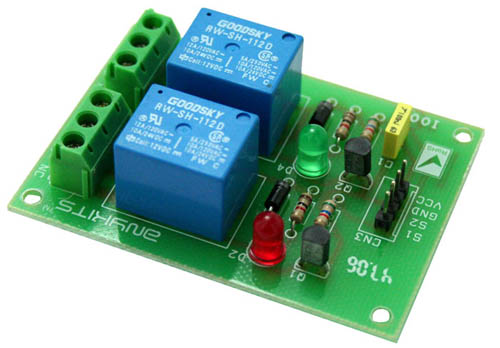
This project is a 2 Channel Relay Board.
Description
2 channel Relay driver project can be controlled by feeding 2-12V trigger voltage, Very useful project for application like Micro-Controller based projects, Remote controller, Lamp on Off, and any circuits which required isolated high current and high voltage switching by applying any TTL or CMOS level voltage. Two LED works as operation indicator while in , 3 pins screw terminals to connect load and provides both normally open and normally closed switching.
- Input: 12 VDC @ 84 mA
- Output: Two SPDT relay
- Relay specification: 5 A @ 230 VAC
- Trigger level : 2 to 12 VDC
- Header connector for connecting power and trigger voltage
- LED on each channel indicates relay status
- Power Battery Terminal (PBT) for easy relay output connection
- Four mounting holes of 3.2 mm each
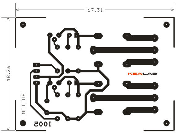
- PCB dimensions 49 mm x 68 mm
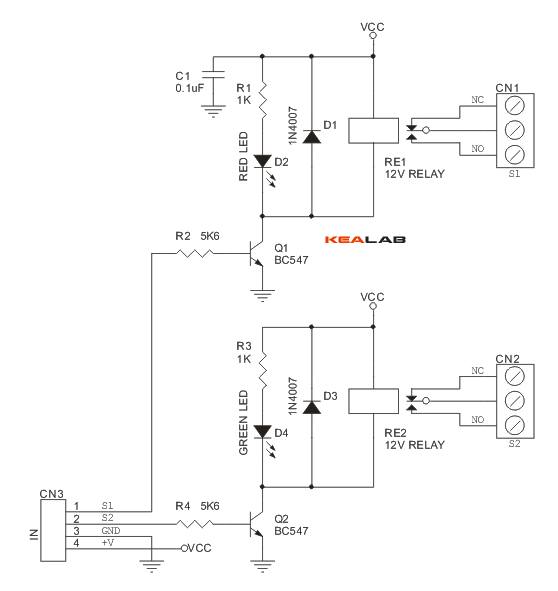
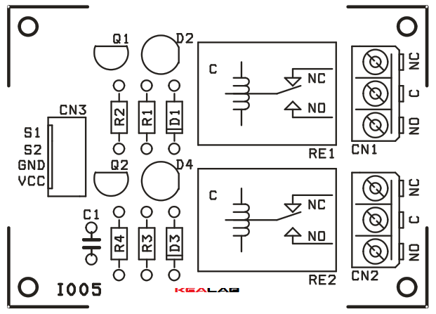
Schematic
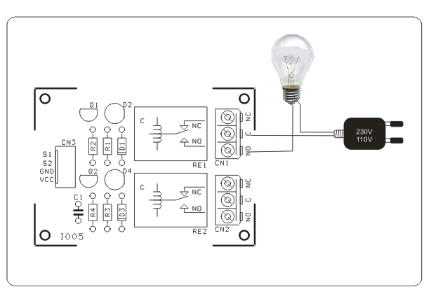
Connection
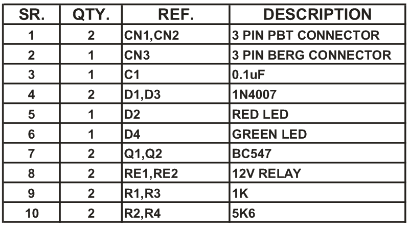
Parts List
Please follow and like us:
PCB


Can be easily convert as a remote switch by an infra-red T / R link , then it is very useful.
You can also check this project: https://www.electronics-lab.com/project/4-channel-infrared-remote-relays/
Can arduino uno connected to laptop fire it up?
what is the purpose of c1 and can i use a ceramic 0.1uF capacitor, if not can you please give me exact specifications of C1
C1 is a filtering cap, used to reject noise from the power source, any 0.1uF cap will do the job.
Dear
If i Want to use 5v Relay What Should I need to Change in the Circuit? In additional to it i also want to add HLK-PM01 – AC-DC-converter to supply 5v Relay More over I also want to connect this Relay to Arduino Uno or Node Mcu Via Wifi.
Awaiting for reply
It should work with 5V relays as it is. You can give it a try.
If i want to join with dc motor.
What should i do?
You can use this board to control any DC motor up to few A. It all depends on the relay rating.
please add pcb layout in pdf
PCB and Schematic PDF are added above. Thanks