

32 band Audio Spectrum Analyzer using OLED display and Attiny85
- Emmanuel Odunlade
- https://twitter.com/emmaodunlade
- emmaodunlade@gmail.com
- 9.552 Views
- moderate
- Tested
- 1 Likes

Visualizations are an important part of a music player. They provide the user with something to feast their eyes on especially when the music has no video. For today’s tutorial, we will build a visualization device, capable of providing a visual representation for any kind of music fed into it.
The goal of this project is to get smooth, appealing music visualization on the ATTiny85, optimizing around its limited speed and resources (RAM and program memory). It’s an ongoing project being developed by GitHub user Colonel Watch, which is mostly complete but it’s otherwise fully functional and ready to be flashed.
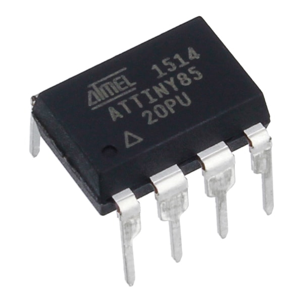
At the heart of today’s project is the Attiny85 which is an 8-bit, low power AVR microcontroller based on RISC CPU architecture and comes as an 8-pin PDIP interface. It is a very small microcontroller with impressive inbuilt functions that helps it perform wonderfully well and fits into the needs of users who want a very tiny DIP microcontroller.
Some of the features of the attiny85 include;
- Flash type Program Memory
- 8Kb flash memory
- 20 MIPS/DMIPS CPU Speed
- 512 bytes of SRAM
- 512 bytes of EEPROM
- Supports SPI(1) and I2C(1) communication protocols
- 5 PWM pins
- 8-bit Timers (2)
- 1.8v – 5.5V operating voltage
For this project, the Attiny85 is charged with obtaining the signal through the analog frontend created along it’s ADC, then compute the signal and display the output.
Required Components
The following components are required to build this project;
- ATTiny85
- SSD1306 OLED Module
- 3-Pole Audio Jack (1, 2 for pass-through)
- 2N3904 or other NPN transistor
- 0.1uF Capacitor
- Potentiometer (any value above 10k)
- 200 Ohm Resistor (2)
- 820 Ohm Resistor
- 100k Ohm Resistor
- External 5V Power Supply
These components can all be bought from any electronics store, online or offline.
Schematics
The schematics for today’s project is not as straightforward as often as we have to interconnect a couple of resistors and other passives.
Connect the components as shown in the schematics below.
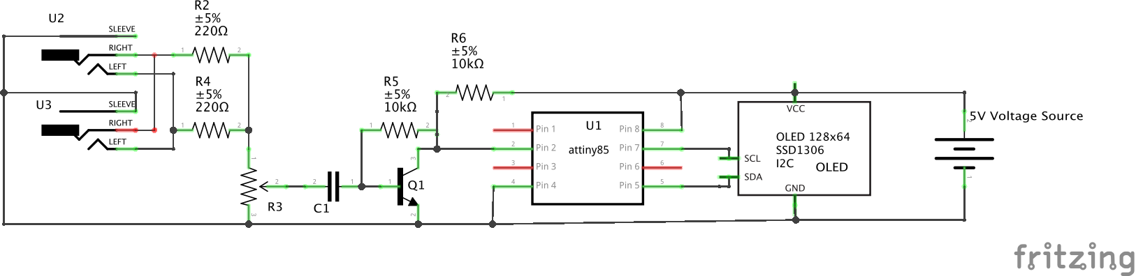
The idea behind the schematics is to allow us to receive audio inputs from the audio jacks, process the sound signals and feed into an analog pin on the Attiny85, which then processes the signal and generates the data which is communicated to the OLED for display via I2C.
Since the other connections are a bit difficult to describe on a pin to pin level, we will only look at that of the OLED and the Attiny. The pin to pin connection between the Attiny85 and the OLED is described in the pin map below.
OLED – Attiny85
SDA - Pin 5
SCL - Pin 7
VCC - 5V
GND - GND
With this done, we are now ready to write the code for the project. Go over the connections once again to ensure everything is as it should be.
Code
As mentioned earlier, the goal for this project is to display smooth and appealing sound visualization. To work around the limited resources in terms of the RAM size of the Attiny85 and the poor quality of the OLED display, we will use two libraries; the fix_fft, the nano_engine library, and the ssd1306 libraries. The fix_fft is an AVR implementation of a faster 8-bit integer-based FFT for signal processing while the SSD1306 library will help reduce the size and complexity of the code we need to write to display data on the OLED. The nano_engine library will be used to draw sector by sector lines on the OLED because the attiny85 can’t hold a full buffer.
As usual, I will be doing a breakdown/quick explanation of the code to explain its technical parts.
We start the code by including the libraries that we will use.
// Copyright [2019] [colonelwatch]

#include "fix_fft.h"                  // 8-bit FFT library modified for Arduino
#include "ssd1306.h"                  // library for OLED
#include "nano_engine.h"              // library for nanoengine (which draws sector-by-sector on OLED because the ATtiny85 can't hold a full buffer)
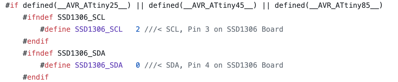
Next, we need to configure the SSD1306 library to suit our Attiny85 by setting the SDA and SCL pins to 0 and 2 respectively. To do this, we need to take a detour and visit the SSD1306 library to make the adjustments. Go to the SSD1306 library and open the ssd1306_12c.conf.h file. You can follow this path (libraries\ssd1306\src\intf\i2c\ssd1306_i2c_conf.h ) to get to it. Open the file and assign the SDA pin to 0 and the SCL pin to 2 like shown in the image below.
With that done, we create some of the variables that we will use to store various data in the code.
// These are user-adjustable
//#define LOG_OUTPUT              // Uncomment to enable logarithmic output (exchanges absolute resoluton for more readable output; may require different below params)
#define SAMPLING_FREQUENCY 15000  // Sampling frequency (Actual max measured frequency captured is half)
#define TIME_FACTOR 3             // Smoothing factor (lower is more dynamic, higher is smoother) ranging from 1 to 10+
#define SCALE_FACTOR 12           // Direct scaling factor (raise for higher bars, lower for shorter bars)

#ifdef LOG_OUTPUT
const float log_scale = 64./log(64./SCALE_FACTOR + 1.);                              // Attempts to create an equivalent to SCALE_FACTOR for log function
#endif
const float coeff = 1./TIME_FACTOR;                                                  // Time smoothing coefficients (used to factor in previous data)
const float anti_coeff = (TIME_FACTOR-1.)/TIME_FACTOR;
const unsigned int sampling_period_us = round(1000000 * (2.0 / SAMPLING_FREQUENCY)); // Sampling period (doubled to account for overclock)

int8_t data[64], buff[32];                                     // used to store FFT input/output and past data
unsigned long microseconds;                                    // used for timekeeping
int summ, avg;
The above variables are important and can vary as they are used in setting the size of the bars, frequency of display, resolution and other related parameters.
Next, we create an instance of the nano engine library and then move to the void setup function.
NanoEngine<TILE_32x32_MONO> engine;
The void setup() function contains a vital piece of actions. We start by overclocking the CPU to around 30MHz to increase the sampling rate and overall processor speed in a way to improve the result and fluidity on the display.
OSCCAL = 240; // Overclocks the MCU to around 30 MHz, set lower if this causes instability, raise if you can/want
Next, we set the value of the ADC Clock to align with the sample rate we have in mind, we then proceed to initialize the SSD1306 display and start the nano engine.
ADCSRA &= ~(bit (ADPS0) | bit (ADPS1) | bit (ADPS2));       // clear ADC prescaler bits
  ADCSRA |= bit (ADPS2);                                      // sets ADC clock in excess of 10kHz
  ADCSRA |= bit (ADPS0);

  ssd1306_128x64_i2c_init();                                  // initializes OLED
  ssd1306_clearScreen();                                      // clears OLED

  engine.begin();                                             // inititalizes nanoengine
};
With that done, we move to the void loop function.
We start this function by reading the analog pin to which the processed audio signal is connected on the attiny85.
summ = 0;
  for (int i = 0; i < 64; i++) {
    microseconds = micros();

    data[i] = ((analogRead(A3)) >> 2) - 128;                        // Fitting analogRead data (range:0 - 1023) to int8_t array (range:-128 - 127)
    summ += data[i];
    while (micros() < (microseconds + sampling_period_us)) {        // Timing out uC ADC to fulfill sampling frequency requirement
    }
  }
The DC component of the signal is then eliminated to ensure the data is usable for the FFT analysis.
avg = summ/64;
  for (int i = 0; i < 64; i++){
    data[i] -= avg;
  }
With this done, we then call the FFT function to perform the Fast Fourier transform on the signal.
fix_fftr(data, 6, 0); // Performing real FFT
The predefined user-determined scaling factors are then used to fine tune and smoothing the signal to generate the output signal values for display.
// Time smoothing by user-determined factor and user-determined scaling
  for(int count = 0; count < 32; count++){
  if(data[count] < 0) data[count] = 0;                                          // Eliminating negative output of fix_fftr
  #ifdef LOG_OUTPUT
  else data[count] = log_scale*log((float)(data[count]+1));                     // Logarithmic function equivalent to SCALING_FACTOR*log2(x+1)
  #else
  else data[count] *= SCALE_FACTOR;                                             // Linear scaling up according to SCALE_FACTOR
  #endif
  data[count] = (float)buff[count] * anti_coeff + (float)data[count] * coeff;   // Smoothing by factoring in past data
  buff[count] = data[count];                                                    // Storing current output as next frame's past data
  if(data[count] > 63) data[count] = 63;                                        // Capping output at screen height
  }
Since the attiny85 cant hold a full buffer, the data to be displayed is first parsed by the nano_engine object Engine that we created earlier. The nano engine then draws a line by line representation of the signal on the OLED Display. The loop continues and as soon as new signal/sound arrives, it is processed and added on the display, creating the soothing visualization desired.
engine.canvas.clear();                                          // Clear canvas as previous data
  for(int i = 0; i < 8; i++){
    engine.canvas.drawVLine(i*4,31-(data[i]+1),31);          // Draw to canvas data for lower-leftest sector (FFT bins 0 - 7, lower half)
  }
  engine.canvas.blt(0,32);                                        // Outputs canvas to OLED with an offset (x pixels, y pixels)
  engine.canvas.clear();
  for(int i = 0; i < 8; i++){
    if(data[i] > 31) engine.canvas.drawVLine(i*4,31-(data[i]-31),31);     // Draw to canvas data for upper-leftest sector (FFT bins 0 - 7, upper half)
  }
  engine.canvas.blt(0,0);
  engine.canvas.clear();
  for(int i = 8; i < 16; i++){
    engine.canvas.drawVLine((i-8)*4,31-(data[i]+1),31);      // FFT bins 8 - 15, lower half
  }
  engine.canvas.blt(32,32);
  engine.canvas.clear();
  for(int i = 8; i < 16; i++){
    if(data[i] > 31) engine.canvas.drawVLine((i-8)*4,31-(data[i]-31),31);   // FFT bins 9 - 15, upper half
  }
  engine.canvas.blt(32,0);
  engine.canvas.clear();
  for(int i = 16; i < 24; i++){
    engine.canvas.drawVLine((i-16)*4,31-(data[i]+1),31);     // FFT bins 16 - 23, lower half
  }
  engine.canvas.blt(64,32);
  engine.canvas.clear();
  for(int i = 16; i < 24; i++){
    if(data[i] > 31) engine.canvas.drawVLine((i-16)*4,31-(data[i]-31),31);  // FFT bins 16 - 23, upper half
  }
  engine.canvas.blt(64,0);
  engine.canvas.clear();
  for(int i = 24; i < 32; i++){
    engine.canvas.drawVLine((i-24)*4,31-(data[i]+1),31);     // FFT bins 24 - 31, lower half
  }
  engine.canvas.blt(96,32);
  engine.canvas.clear();
  for(int i = 24; i < 32; i++){
    if(data[i] > 31) engine.canvas.drawVLine((i-24)*4,31-(data[i]-31),31);  // FFT bins 24 - 31, upper half
  }
  engine.canvas.blt(96,0);
The complete code for the project can be found below and is also attached under the download section along with other project files.
// Copyright [2019] [colonelwatch]

#include "fix_fft.h"                  // 8-bit FFT library modified for Arduino
#include "ssd1306.h"                  // library for OLED
#include "nano_engine.h"              // library for nanoengine (which draws sector-by-sector on OLED because the ATtiny85 can't hold a full buffer)

// To get this program to operate, the SDA and SCL pins must be reassigned to 0 and 2 respectively in the library header file
// The file is located in libraries\ssd1306\src\intf\i2c\ssd1306_i2c_conf.h
// Make sure to undo this if the library will be used again in the future

// These are user-adjustable
//#define LOG_OUTPUT              // Uncomment to enable logarithmic output (exchanges absolute resoluton for more readable output; may require different below params)
#define SAMPLING_FREQUENCY 15000  // Sampling frequency (Actual max measured frequency captured is half)
#define TIME_FACTOR 3             // Smoothing factor (lower is more dynamic, higher is smoother) ranging from 1 to 10+
#define SCALE_FACTOR 12           // Direct scaling factor (raise for higher bars, lower for shorter bars)

#ifdef LOG_OUTPUT
const float log_scale = 64./log(64./SCALE_FACTOR + 1.);                              // Attempts to create an equivalent to SCALE_FACTOR for log function
#endif
const float coeff = 1./TIME_FACTOR;                                                  // Time smoothing coefficients (used to factor in previous data)
const float anti_coeff = (TIME_FACTOR-1.)/TIME_FACTOR;
const unsigned int sampling_period_us = round(1000000 * (2.0 / SAMPLING_FREQUENCY)); // Sampling period (doubled to account for overclock)

int8_t data[64], buff[32];                                     // used to store FFT input/output and past data
unsigned long microseconds;                                    // used for timekeeping
int summ, avg;                                                 // used for DC bias elimination

NanoEngine<TILE_32x32_MONO> engine;                            // declares nanoengine

void setup()
{
  OSCCAL = 240; // Overclocks the MCU to around 30 MHz, set lower if this causes instability, raise if you can/want

  ADCSRA &= ~(bit (ADPS0) | bit (ADPS1) | bit (ADPS2));       // clear ADC prescaler bits
  ADCSRA |= bit (ADPS2);                                      // sets ADC clock in excess of 10kHz
  ADCSRA |= bit (ADPS0);

  ssd1306_128x64_i2c_init();                                  // initializes OLED
  ssd1306_clearScreen();                                      // clears OLED

  engine.begin();                                             // inititalizes nanoengine
};

void loop()
{
  summ = 0;
  for (int i = 0; i < 64; i++) {
    microseconds = micros();

    data[i] = ((analogRead(A3)) >> 2) - 128;                        // Fitting analogRead data (range:0 - 1023) to int8_t array (range:-128 - 127)
    summ += data[i];
    while (micros() < (microseconds + sampling_period_us)) {        // Timing out uC ADC to fulfill sampling frequency requirement
    }
  }

  // Eliminating remaining DC component (produces usable data in FFT bin #0, which is usually swamped by DC bias)
  avg = summ/64;
  for (int i = 0; i < 64; i++){
    data[i] -= avg;
  }

  fix_fftr(data, 6, 0);                             // Performing real FFT

  // Time smoothing by user-determined factor and user-determined scaling
  for(int count = 0; count < 32; count++){
  if(data[count] < 0) data[count] = 0;                                          // Eliminating negative output of fix_fftr
  #ifdef LOG_OUTPUT
  else data[count] = log_scale*log((float)(data[count]+1));                     // Logarithmic function equivalent to SCALING_FACTOR*log2(x+1)
  #else
  else data[count] *= SCALE_FACTOR;                                             // Linear scaling up according to SCALE_FACTOR
  #endif
  data[count] = (float)buff[count] * anti_coeff + (float)data[count] * coeff;   // Smoothing by factoring in past data
  buff[count] = data[count];                                                    // Storing current output as next frame's past data
  if(data[count] > 63) data[count] = 63;                                        // Capping output at screen height
  }

  // Output to SSD1306 using nanoengine canvas from library
  engine.refresh();                                               // Mark entire screen to be refreshed
  engine.canvas.clear();                                          // Clear canvas as previous data
  for(int i = 0; i < 8; i++){
    engine.canvas.drawVLine(i*4,31-(data[i]+1),31);          // Draw to canvas data for lower-leftest sector (FFT bins 0 - 7, lower half)
  }
  engine.canvas.blt(0,32);                                        // Outputs canvas to OLED with an offset (x pixels, y pixels)
  engine.canvas.clear();
  for(int i = 0; i < 8; i++){
    if(data[i] > 31) engine.canvas.drawVLine(i*4,31-(data[i]-31),31);     // Draw to canvas data for upper-leftest sector (FFT bins 0 - 7, upper half)
  }
  engine.canvas.blt(0,0);
  engine.canvas.clear();
  for(int i = 8; i < 16; i++){
    engine.canvas.drawVLine((i-8)*4,31-(data[i]+1),31);      // FFT bins 8 - 15, lower half
  }
  engine.canvas.blt(32,32);
  engine.canvas.clear();
  for(int i = 8; i < 16; i++){
    if(data[i] > 31) engine.canvas.drawVLine((i-8)*4,31-(data[i]-31),31);   // FFT bins 9 - 15, upper half
  }
  engine.canvas.blt(32,0);
  engine.canvas.clear();
  for(int i = 16; i < 24; i++){
    engine.canvas.drawVLine((i-16)*4,31-(data[i]+1),31);     // FFT bins 16 - 23, lower half
  }
  engine.canvas.blt(64,32);
  engine.canvas.clear();
  for(int i = 16; i < 24; i++){
    if(data[i] > 31) engine.canvas.drawVLine((i-16)*4,31-(data[i]-31),31);  // FFT bins 16 - 23, upper half
  }
  engine.canvas.blt(64,0);
  engine.canvas.clear();
  for(int i = 24; i < 32; i++){
    engine.canvas.drawVLine((i-24)*4,31-(data[i]+1),31);     // FFT bins 24 - 31, lower half
  }
  engine.canvas.blt(96,32);
  engine.canvas.clear();
  for(int i = 24; i < 32; i++){
    if(data[i] > 31) engine.canvas.drawVLine((i-24)*4,31-(data[i]-31),31);  // FFT bins 24 - 31, upper half
  }
  engine.canvas.blt(96,0);
}
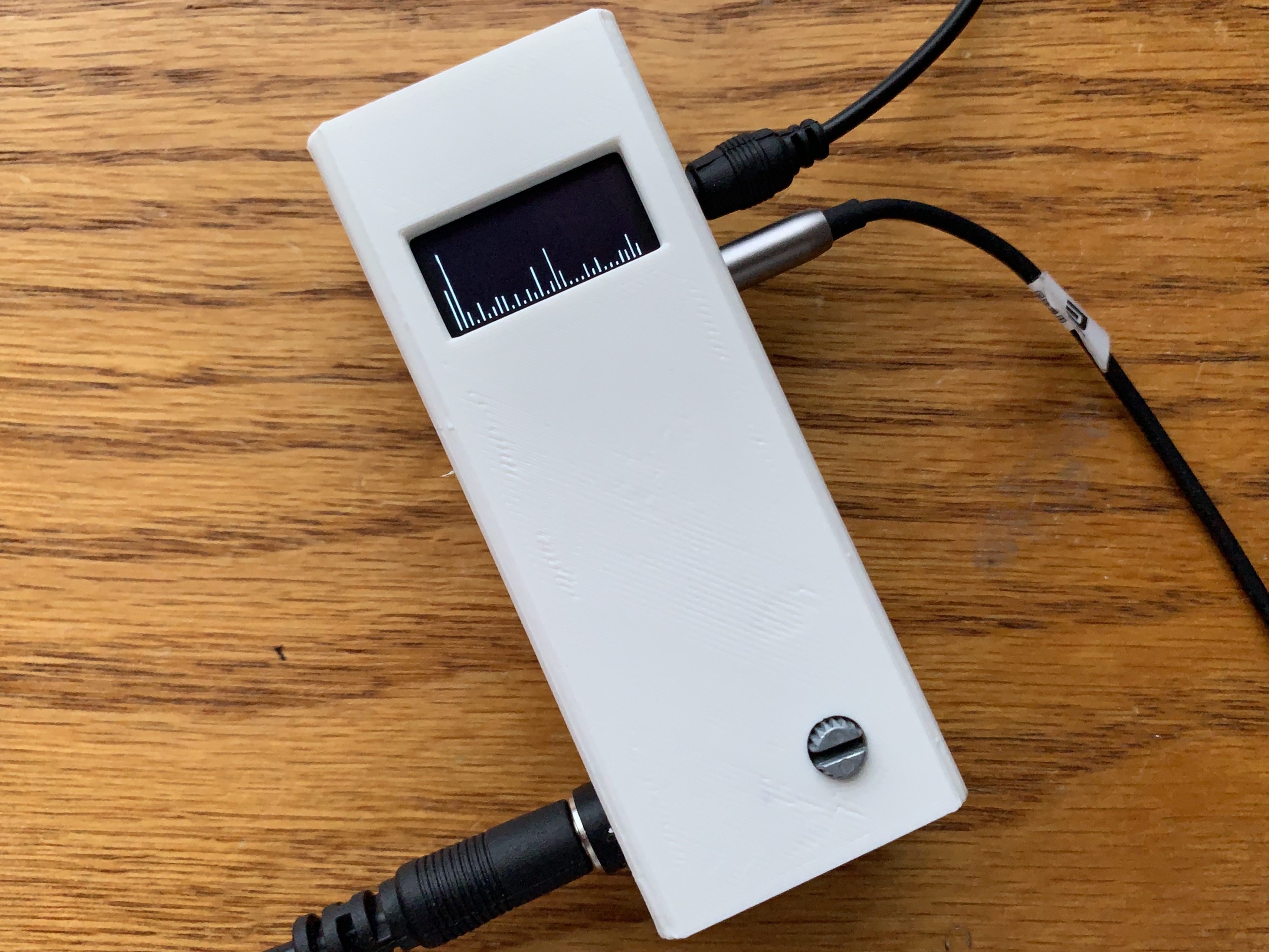
Enclosure Design
To make the project as cool as imagined, it seemed a good idea to design and 3D print an enclosure for it. The created enclosure was designed in such a way that accommodated the screen and the audio jacks in a nice way.
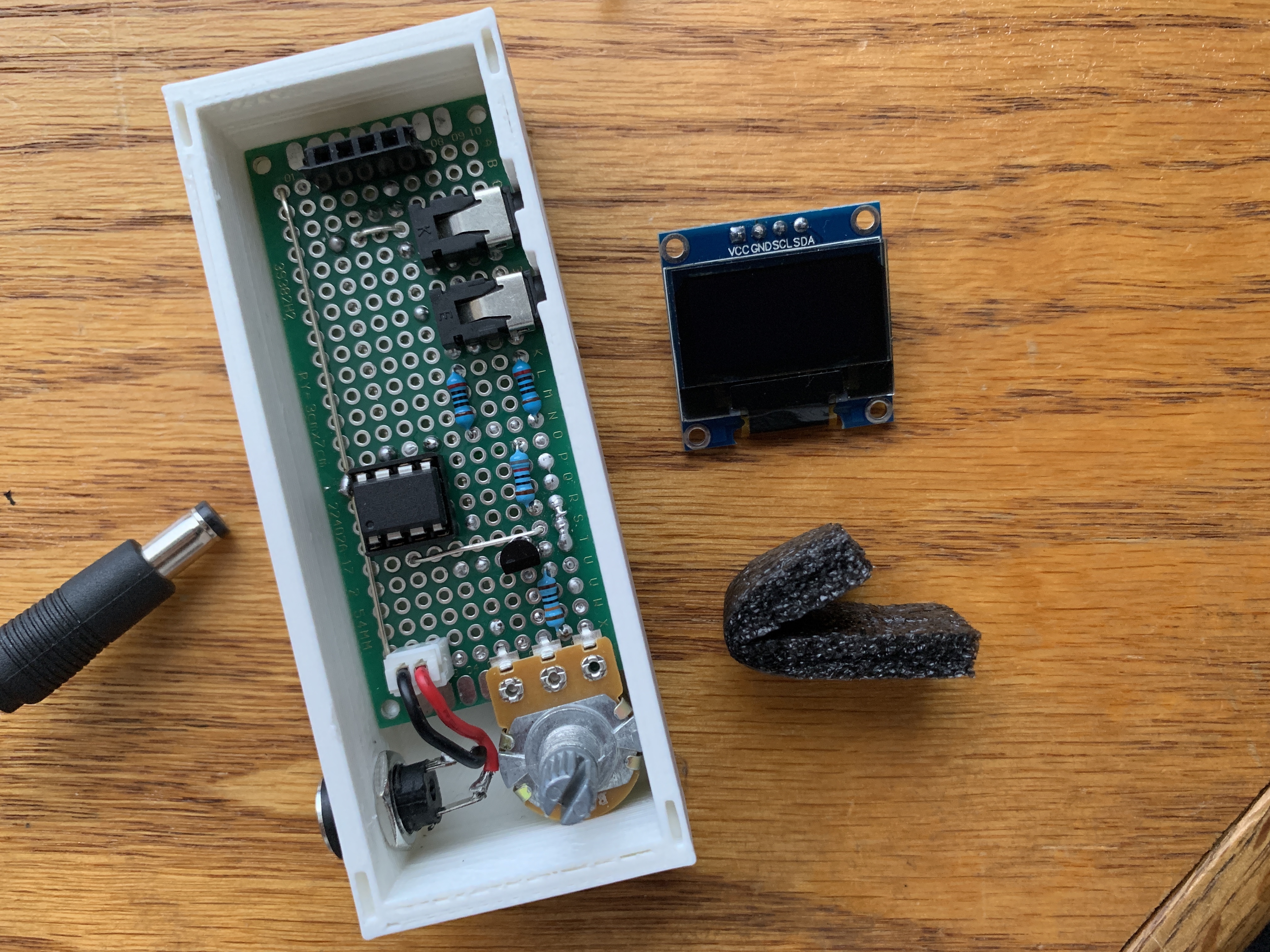
The STL files for the enclosure are also included in the download files.
Demo
Go over the connections once again and ensure you have all the library for the code installed and that the sketch verifies. With all these checked, Upload the code to your attiny85 following the procedure to program the attiny85 described here.
With the Attiny85 programmed, insert it back into the breadboard and power the system. Connect a sound cable to the jacks, and you should see visualization come up as shown below after a few seconds.
While we only implemented visualization for sound, you could go ahead and turn the system into a full-blown MP3 player by adding components like the DFplayer mini to the setup. Also, the same technique used in creating the visualization could be used in other projects like plotting real-time energy consumption.
That’s it for this tutorial. Feel free to reach out via the comment section with any questions you might have as regards the project.
Project Credit and other files: ColonelWatch


hello Dear, unfortunatelly i know only PIC MCU and microC compiler will be possible traslate spectrum analyzer library and program (+oled display) for 18F26k22 MCU please?
Eager to use this project in DIY HiFi system, and exploring/verifying how the code works, but hitting a compilation error on
Line 62: fix_fftr(data, 6, 0); with message “invalid conversion from ‘int8_t* {aka signed char*}’ to ‘char*’ [-fpermissive]”
This is a selection of the compilation output:
Any suggestion to resolve this error??
Thanks
An update on the compilation error.
Wrong version of fix_fft was installed.
Arduino library manager installed a version by Dimitrios Bouras, not the version by kosme on github.
Replaced the Bouras version with the kosme one, and the code compiles correctly.