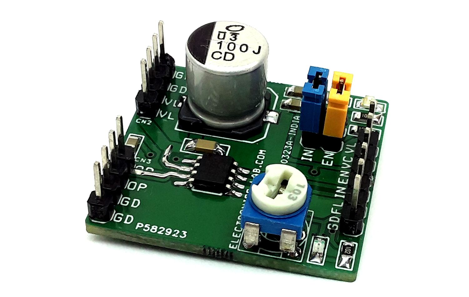
55V – 3A Half-Bridge Power Driver Module
- Rajkumar Sharma
- 157 Views
- moderate
- Tested
- SKU: EL134982
- Quote Now
- 0 Likes

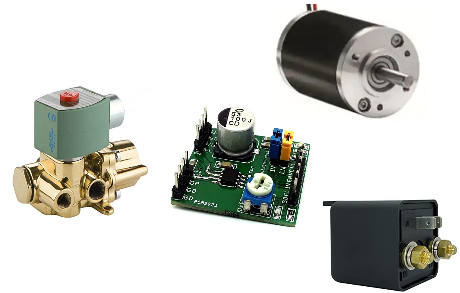
This Half-bridge module provides current measurement and regulation features for various loads. The module can be used to drive solenoids, Relays, Valves, DC-DC converters, Brushed DC motors, or other loads. It can operate from a 5V to 55V supply voltage and can deliver up to 3A of output current (depending on ambient temperature). Cycle-by-cycle current regulation, current limiting is adjustable using PR1 trimmer pot. Internal diagnostic and protection features include open-load detection, over-current protection (OCP), under-voltage lockout (UVLO), and thermal shutdown. The overcurrent limit is set to 3A and the retry time is 1.6mS. Solenoids can be controlled ON/OFF using Jumper J1. Use the PWM signal at the input pin for DC motor speed control.
Features
- Load Supply: Wide 5V to 55V Input Voltage Range
- 3A Maximum Output Current
- Cycle-by-Cycle Current Regulation/Limiting
- Adjustable Current Limit Using Trimmer POT
- On Board Power LED
- On Board Fault LED
- Fault Indication Output Logic Low Indicates Fault
- Low On-Resistance (High Side: 100mΩ (Internal Resistor Chip)
- Low Side: 120mΩ) (Internal Resistor Chip)
- No Control Power Supply Required
- Simple, Versatile Logic Interfaces
- Inputs Compatible with 2.5V, 3.3V, and 5V Logic
- Over-Current Protection (OCP), Trip Level 3Amps, Retry Time 1.6mS
- Open-Load Detection
- Thermal Shutdown, Threshold 165 Degree Cent. (Thermal shutdown hysteresis 15 Degree Cent.)
- Under-Voltage Lockout (UVLO), Threshold 4.1V
- PCB Dimensions 31.12 x 29.21mm
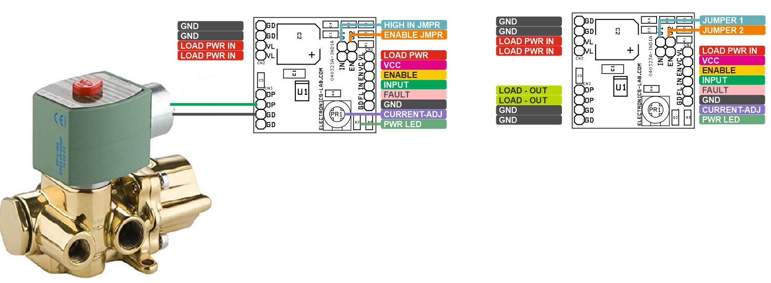
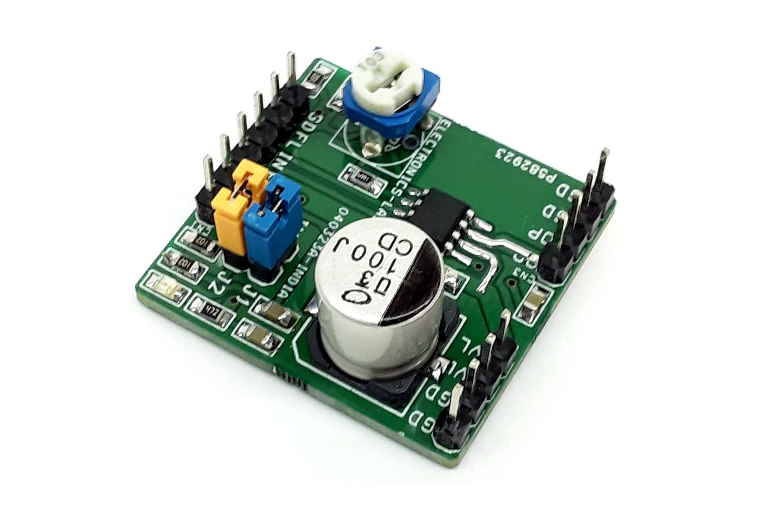
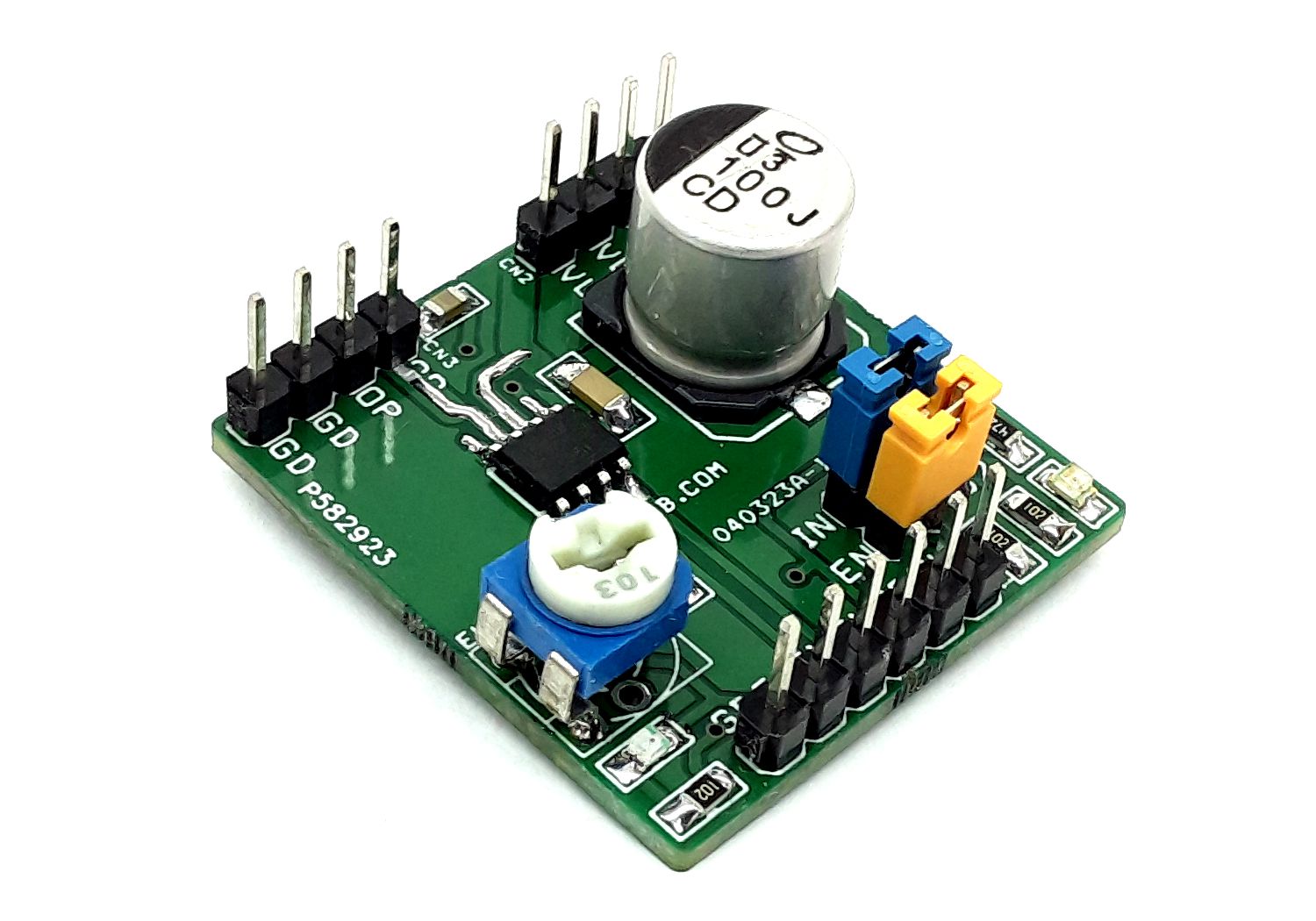
Connections and Other Details
- CN1: Pin 1 = Load Supply, Pin 2 = VCC, Pin 3 = Enable (High=Enable) , Pin 4 = PWM/Logic In, Pin 5 = Fault logic low if a fault condition (e.g. OCP, OTP, or open load occurs, Pin 6 = GND
- CN2: Pin 1 & 2 = Load Supply 5V to 55V DC, Pin 3 & 4 = GND
- CN3: Pin 1 & 2 = Load Output, Pin 3 & 4 = GND
- Jumper J1 = Internal Enable, Don’t Use this Jumper In case External Enable Input CN1 Pin 3 Required
- Jumper J2 = Output Direct Triger, Don’t Use this Jumper In Case External PWM Input CN1 Pin 4 Required
- D1: Power LED
- D2: Fault LED, Glow if a fault condition (e.g. over-current protection [OCP], over-temperature protection [OTP], or open load) occurs
- PR1: Trimmer Potentiometer to Set the Current Limit
Input Logic: Each MOSFET in the MPQ6610 is controlled independently using the IN and EN pins
- Enable Low, In Low Output Hi-Z
- Enable Low, In High Output Hi-Z
- Enable High, In Low Output Low
- Enable High, In High Output High
The input pins are designed such that they can be driven with a logic level voltage even when the main power to the device is inactive.
Current-Sense
The current flowing in the low-side MOSFET (LS-FET) or high-side MOSFET (HS-FET) is sensed with an internal current-sense circuit. A voltage that is proportional to the output current is sourced on the ISET pin. The ISET pin voltage scaling is set by a resistor connected between the ISET pin and ground. For 1A of output current, 100µA of current is sourced into the resistor connected to ISET. For example, if a 10kΩ resistor is connected between ISET and ground, the output voltage on the ISET pin is 1V/A of output current. The current is sensed anytime that either the LS-FET or HS-FET is on.
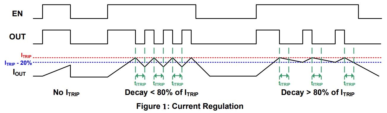
Current Limit and Regulation
The current in the output is limited using constant-off-time (COT) pulse-width modulation (PWM) control circuitry. Figure 1 shows the device’s current regulation system, described below:
- First, a MOSFET turns on and drives current through the load.
- The current increases in the load, which is then sensed by the internal current-sense circuit.
- If the load current reaches the current trip threshold, the output changes its state (if it was driving high, it goes low; if it was driving low, it goes high).
- If the load current has fallen at 80% of the current limit threshold after a fixed off time (tITRIP), the original MOSFET is re-enabled. Then the cycle repeats.
- If the current is still above this level, the off time is extended until the current falls to 80% of the current limit threshold.
The current limit threshold is reached when the ISET pin reaches 1.5V. For example, with a 10kΩ resistor (R4 + PR1) connected from ISET to ground, the ISET pin voltage is 1V/A of output current. Therefore, when the current reaches 1.5A, the ISET pin voltage reaches 1.5V, and a current trip occurs.
Blanking Time
There is often a current spike while the MOSFET turns on, which can be caused by the body diode’s reverse recovery current or by the shunt capacitance of the load. This current spike requires filtering to prevent it from erroneously shutting down the enabled MOSFET. An internal fixed blanking time (tBLANK) blanks the output of the current-sense comparator when the output is switched. This blanking time also sets the minimum time for which the output remains high or low after the input has changed.
Protection and Diagnostic Functions
The Module has a FAULT pin, which is driven active low if any of the protection circuits are activated. These fault conditions include over-current (OC) and over-temperature protection (OTP), as well as open-load detection. FAULT is not driven low if a current limit trip occurs. FAULT is an open-drain output, and requires an external pull-up resistor with LED. When the fault condition is removed, the FAULT pin is pulled inactive high by the pull up resistor and LED.
Over-Current Protection (OCP)
If the current through any MOSFET of the chip exceeds the over-current (OC) threshold for longer than the over-current deglitch time, an over-current fault is triggered. If an OC fault occurs, the state of the output is reversed until the current approaches 0A. Then both internal MOSFETs of chip are disabled, and the FAULT pin is driven low. The driver remains disabled for about 1.6ms, then is automatically re-enabled.
Open-Load Detection
When the output is in a high-impedance state (EN = 0), the internal circuits pull the OUT pin to VIN / 2 by a weak current. If a load is connected between OUT and ground, then the load pulls the OUT pin close to ground. If a load is connected to VIN, then OUT is pulled close to the value on VIN. If the voltage on OUT (VOUT) is almost VIN / 2, an open-load condition is detected, and the nFAULT pin is driven active low. The fault is cleared when EN is made active.
Input Under-Voltage Lockout (UVLO) Protection
If the voltage on VIN (VIN) falls below the under-voltage lockout (UVLO) threshold at any time, all circuitry in the device is disabled and the internal logic is reset. Once VIN exceeds the UVLO threshold, the module resumes normal operation.
Over-Voltage Protection (OVP)
If VIN exceeds the over-voltage protection (OVP) threshold, the device is disabled. Once VIN falls below the OVP threshold, the module resumes normal operation.
Thermal Shutdown
If the die temperature exceeds its safe limits, all MOSFETs in the H-bridge are disabled, and the FAULT pin goes low. Once the die temperature drops to a safe level, the device automatically resumes normal operation.
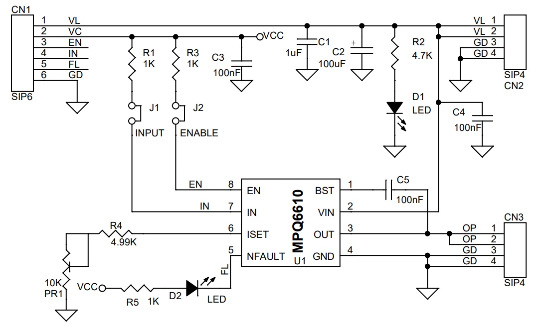
Schematic
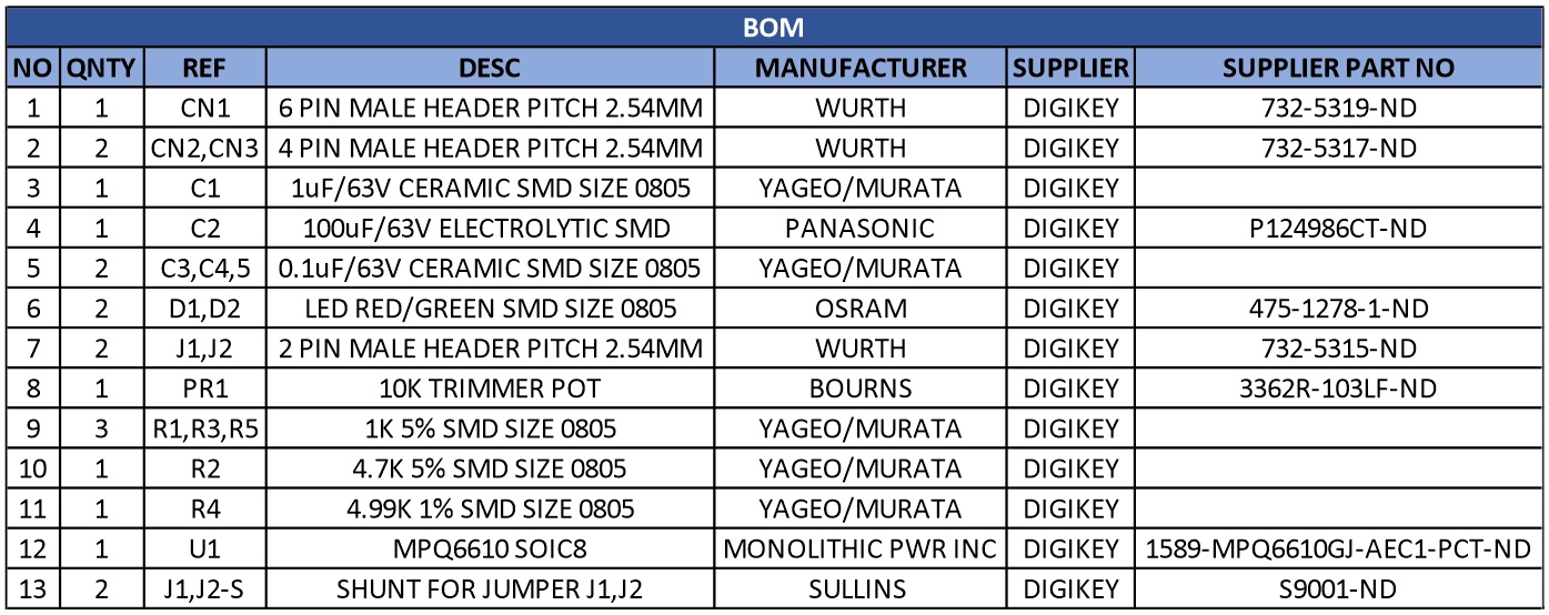
Parts List
| NO | QNTY | REF | DESC | MANUFACTURER | SUPPLIER | SUPPLIER PART NO |
|---|---|---|---|---|---|---|
| 1 | 1 | CN1 | 6 PIN MALE HEADER PITCH 2.54MM | WURTH | DIGIKEY | 732-5319-ND |
| 2 | 2 | CN2,CN3 | 4 PIN MALE HEADER PITCH 2.54MM | WURTH | DIGIKEY | 732-5317-ND |
| 3 | 1 | C1 | 1uF/63V CERAMIC SMD SIZE 0805 | YAGEO/MURATA | DIGIKEY | |
| 4 | 1 | C2 | 100uF/63V ELECTROLYTIC SMD | PANASONIC | DIGIKEY | P124986CT-ND |
| 5 | 2 | C3,C4,5 | 0.1uF/63V CERAMIC SMD SIZE 0805 | YAGEO/MURATA | DIGIKEY | |
| 6 | 2 | D1,D2 | LED RED/GREEN SMD SIZE 0805 | OSRAM | DIGIKEY | 475-1278-1-ND |
| 7 | 2 | J1,J2 | 2 PIN MALE HEADER PITCH 2.54MM | WURTH | DIGIKEY | 732-5315-ND |
| 8 | 1 | PR1 | 10K TRIMMER POT | BOURNS | DIGIKEY | 3362R-103LF-ND |
| 9 | 3 | R1,R3,R5 | 1K 5% SMD SIZE 0805 | YAGEO/MURATA | DIGIKEY | |
| 10 | 1 | R2 | 4.7K 5% SMD SIZE 0805 | YAGEO/MURATA | DIGIKEY | |
| 11 | 1 | R4 | 4.99K 1% SMD SIZE 0805 | YAGEO/MURATA | DIGIKEY | |
| 12 | 1 | U1 | MPQ6610 SOIC8 | MONOLITHIC PWR INC | DIGIKEY | 1589-MPQ6610GJ-AEC1-PCT-ND |
| 13 | 2 | J1,J2-S | SHUNT FOR JUMPER J1,J2 | SULLINS | DIGIKEY | S9001-ND |
Connections
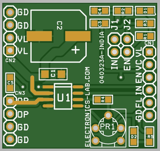
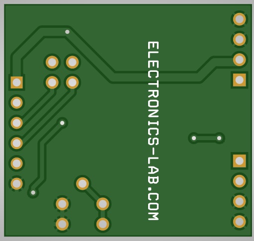
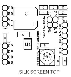
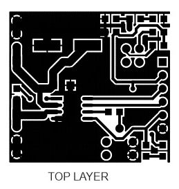
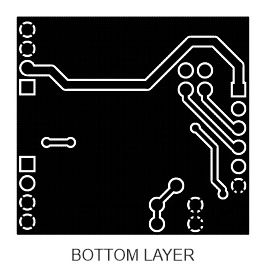
Gerber View
Current Regulation
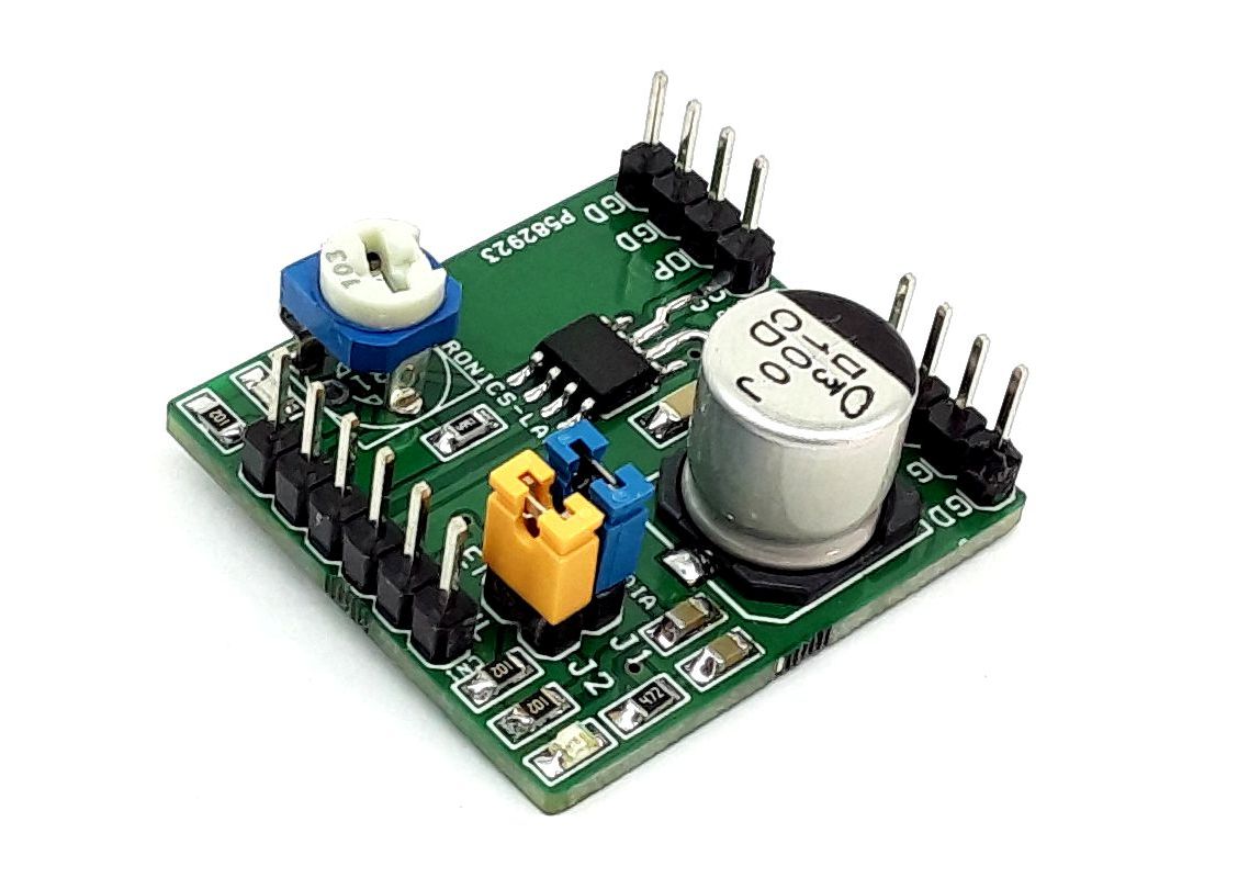
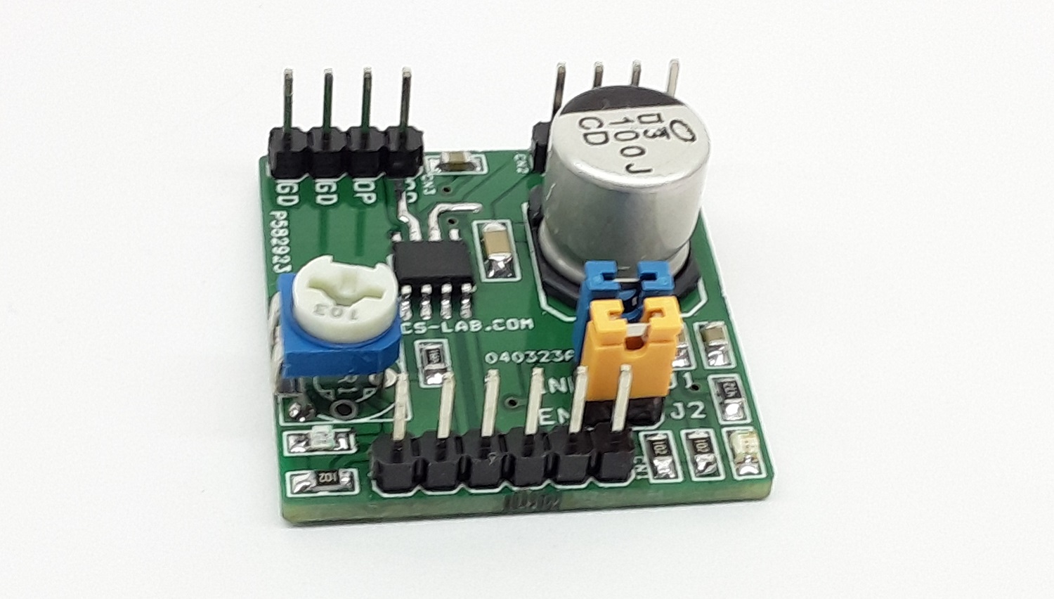
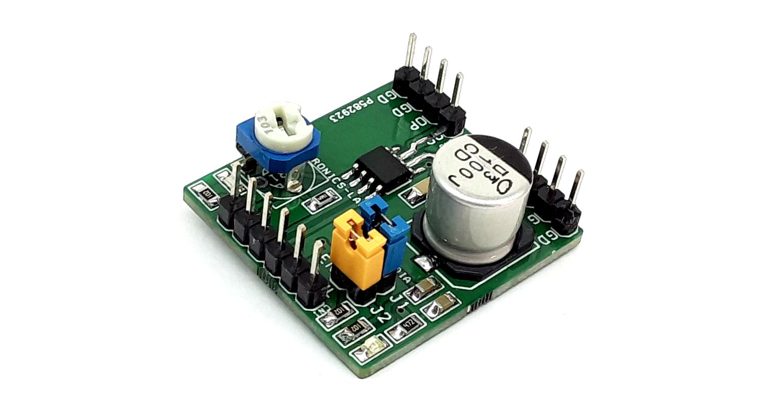
Photos

Video
MPQ6610 Datasheet
PCB