Brushed DC Motor Controller Using Infra-Red Remote
- Rajkumar Sharma
- 3.615 Views
- medium
- Tested
- SKU: EL100687
- Quote Now
- 0 Likes

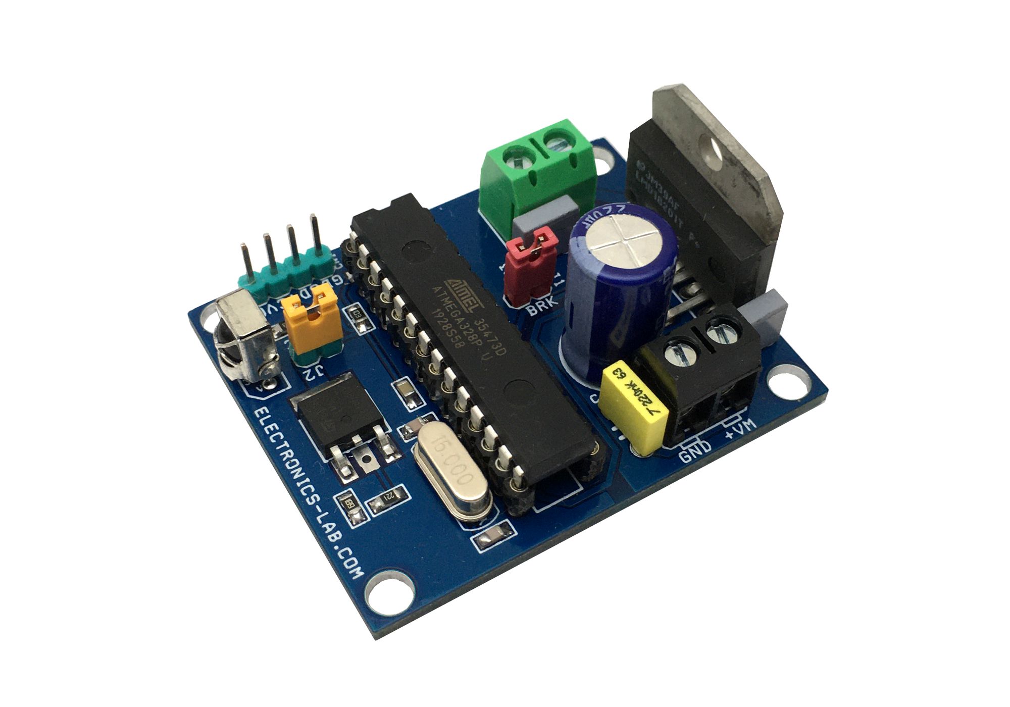
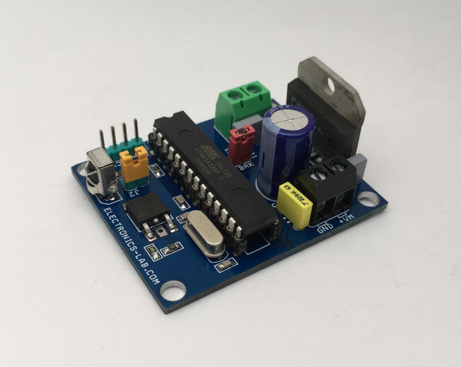
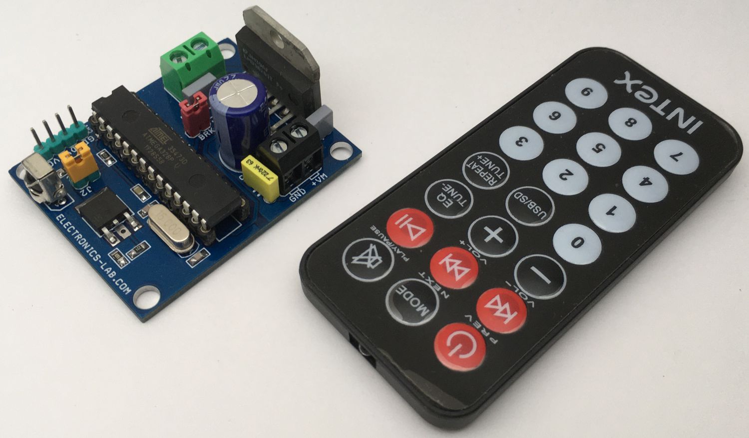
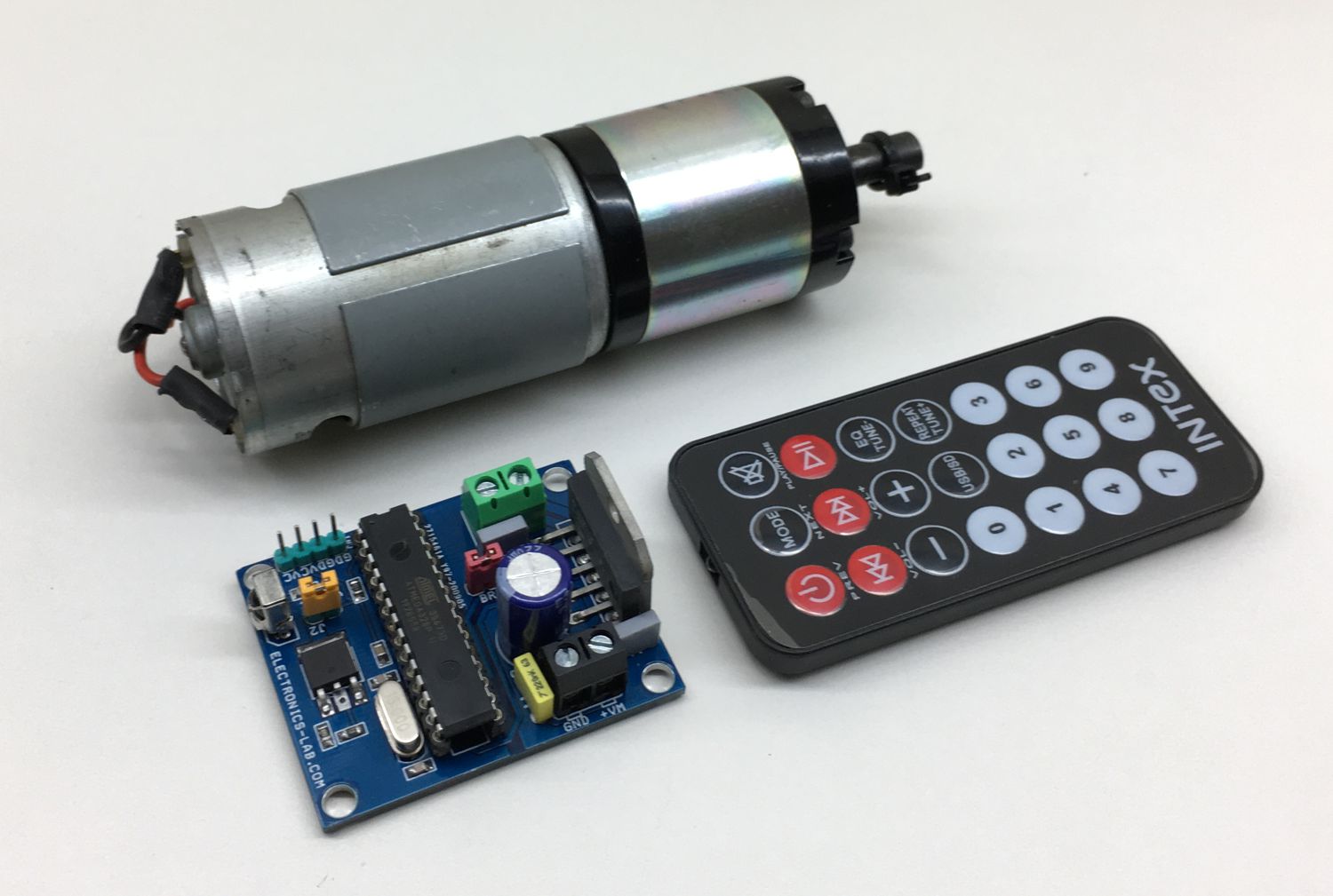
This project enables the user to control a Brushed DC Motor using an Infra-Red Remote Control, thus controlling speed, direction, and also brake of DC Motor is possible. It’s an Arduino compatible open-source hardware that helps you develop many DC Motor control applications. The user has to write the code as per the application requirement. The project is based on three main parts, Atmega328 microcontroller, LMD18201 DC Motor H-bridge, and TSOP1838 Infra-red receiver. This board can control DC motor up to 48V DC with continuous current up to 3A and with peak current 6A.
Example Arduino code is available under Downloads below. This code will help you to control the speed of the motor in 4 steps up/down using an infra-red remote control with help of two switches.
Boot-Loader Burning and Arduino Programming
A new Atmega328 Chip requires Boot Loader Burning to upload Arduino code, refer to the link for further information about the process:
- https://www.electronics-lab.com/project/installing-the-arduino-bootloader-on-the-atmega328p-microcontroller/
- https://www.arduino.cc/en/Tutorial/BuiltInExamples/ArduinoToBreadboard
How to Decode IR Remote Control Signals using Arduino
I have used a mini MP3 remote control to test this project, you can use any IR remote with this project, but the user has to decode the IR remote and define Hex value in Arduino code. More details on decoding IR Remote available here:
- https://www.maxphi.com/ir-remote-control-decoder-using-arduino
- https://create.arduino.cc/projecthub/electropeak/use-an-ir-remote-transmitter-and-receiver-with-arduino-1e6bc8
- https://www.circuitbasics.com/arduino-ir-remote-receiver-tutorial/
Arduino Pins Vs LMD18201 Motor Driver Pins
Arduino Digital D5>>PWM Pin LMD18201, Arduino Digital Pin D11 >> Direction Pin LMD18201, Analog Pin A1 >> Break Pin LMD18201, Arduino Digital pin D2 >> IR Receiver TSOP1838
Power Supply
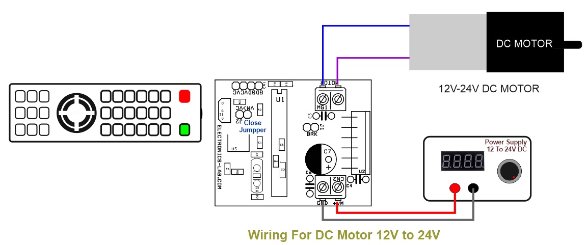
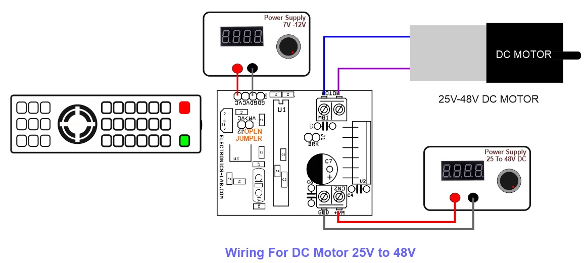
You can run a 12V to 24V motor and in this case, the board requires a single power supply of 12V to 24V DC, to use this option Close the jumper 2 and power the CN2 12V to 24V. To drive a Higher voltage motor, the circuit requires 2 separate power supply for logic and motor, in this case, open the jumper J2, use CN2 to apply motor supply 25V to 48V and CN1 7V to 24V logic supply.
Heat-sink: If you want to fetch full power from LMD18201 IC, it is advisable to use the large size heatsink on LMD18201 IC.
Brake: Brake Jumper J1 is always closed for normal operation with example code. Open the jumper if this option required in operations.
Features
- Operating Power Supply 12V to 24V DC or 25V to 48V DC
- Load Current Up to 3Amps Continues
- D1 Power LED
- IR Remote: Motor Direction CW/CCW, Speed Control, Brake
- On-Board L317ADJ Regulator to Power 5V DC to Atmega328 Chip
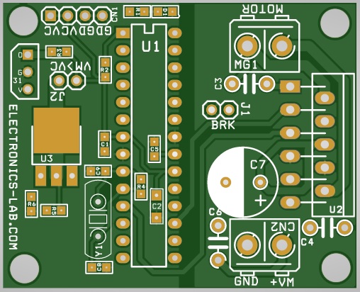
- PCB Dimensions 51.91MM X 41.91MM
LMD18201
The LMD18201 is a 3A H-Bridge designed for motion control applications. The device is built using a multi-technology process which combines bipolar and CMOS control circuitry with DMOS power devices on the same monolithic structure. The H-Bridge configuration is ideal for driving DC and stepper motors. The LMD18201 accommodates peak output currents up to 6A. Current sensing can be achieved via a small sense resistor connected in series with the power ground lead. For current sensing without disturbing the path of current to the load, the LMD18200 is recommended.
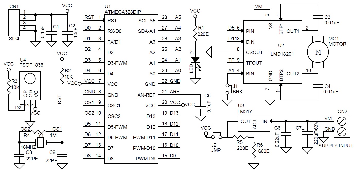
Schematic
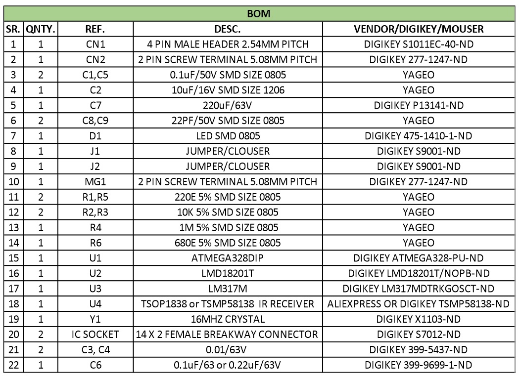
Parts List
Connections
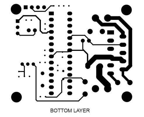
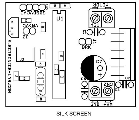
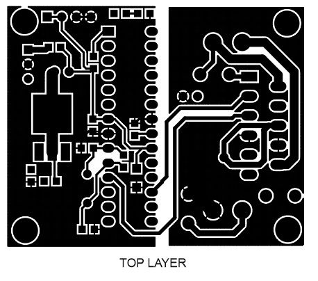
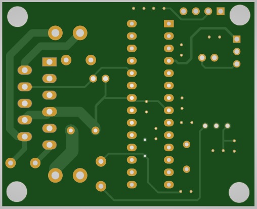
Gerber View
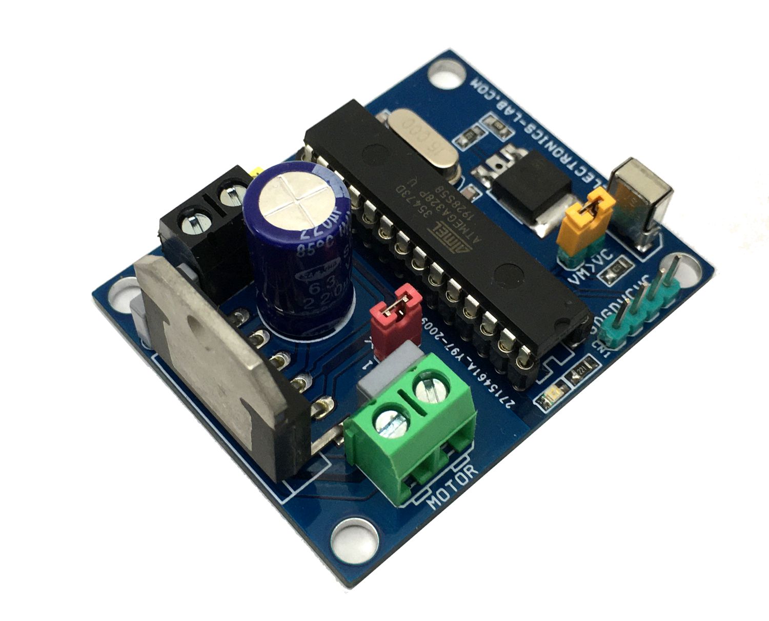
Photos
Video
LMD18201 Datasheet
PCB