Brushed DC Motor Driver with Integrated Current Regulation
- Rajkumar Sharma
- 188 Views
- easy
- Tested
- SKU: EL130495
- Quote Now
- 2 Likes

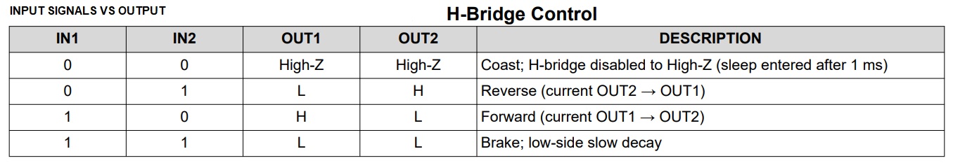
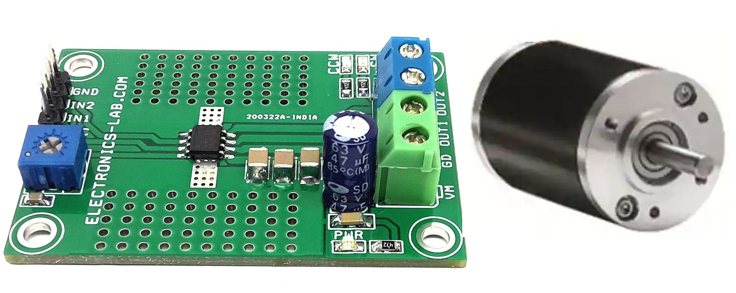
The highly efficient DC brushed motor driver including an onboard shunt resistor for current regulation presented here is built using the DRV8251 chip. The operating supply voltage range of the project is 4.5V to 48V DC and the default output current capability is 2.1A. A trimmer potentiometer PR1 is provided to adjust the current regulation threshold. The device includes under-voltage lockout (UVLO), Latched overcurrent protection (OCP), and thermal shutdown (TSD). Output is disabled and latched when over current/stall current condition occurs. For direction control of the motor use IN1 and IN2 as logic inputs and for speed control these inputs can be connected to a PWM source with duty cycle 0 to 100% and frequency 20Khz.
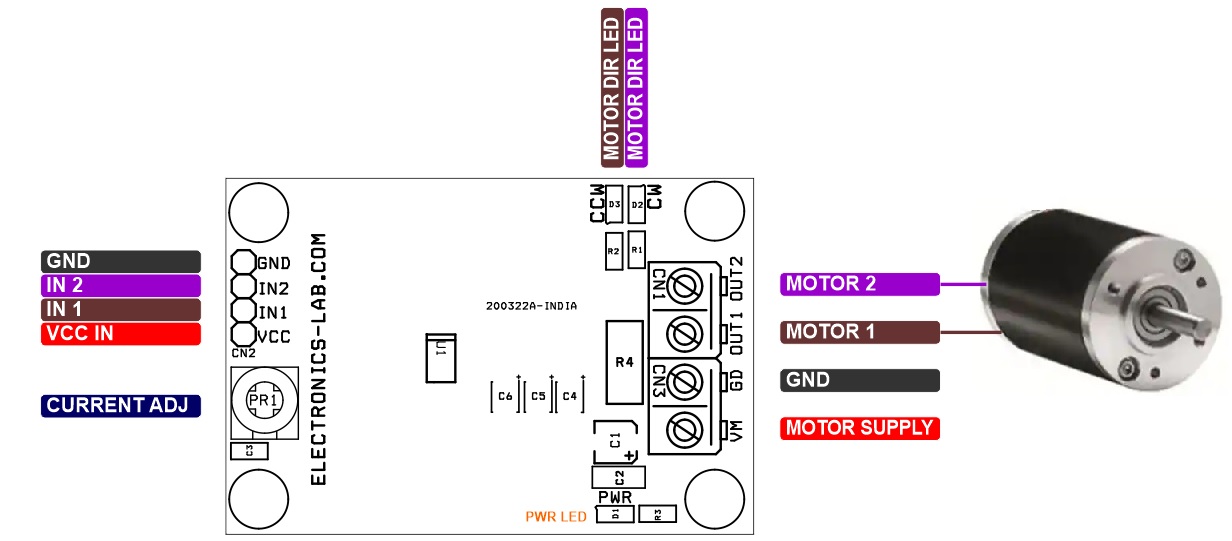
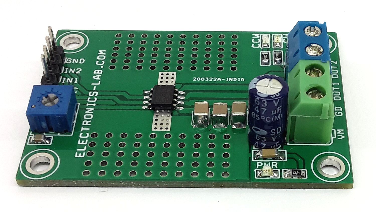
Connections and Other details
- CN1: Pin 1 Output 1, Pin 2 Output 2 (Motor Connections)
- CN2: Pin 1 VCC 5V DC for V-REF, Pin 2 Input 1 PWM or Logic, Pin 3 Input 2 PWM or Logic, Pin 4 GND
- CN3: Pin 1 VM Motor Supply 4.5V to 48V DC, Pin 2 GND
- LED: D2, D3 Motor Direction Indicator
- LED: D1 Power LED
- PR1 Trimmer Potentiometer: Current Regulation Threshold Adjust
Features
- 5V to 48V operating supply voltage range
- VCC Supply 5V DC 10mA (V-Ref = 4V for 2.1A Adjust Using PR1)
- Load Current Up to 2.1Amp
- Motor Trip Point 1.9 Amp
- Pin-to-pin, RDS (on), voltage, and current sense/regulation variants (external shunt resistor and integrated current mirror)
- PWM control interface, PWM Frequency 20Khz (Range Up to 200Khz)
- Supports 1.8-V, 3.3-V, and 5-V logic inputs, IN1 and IN2
- Integrated current regulation
- Low-power sleep mode
- Integrated protection features, VM under-voltage lockout (UVLO), Latched overcurrent protection (OCP)
- Thermal shutdown (TSD)
- PCB Dimensions 55.25 x 37.47mm
- 4 x 3mm Mounting Holes
DRV8251
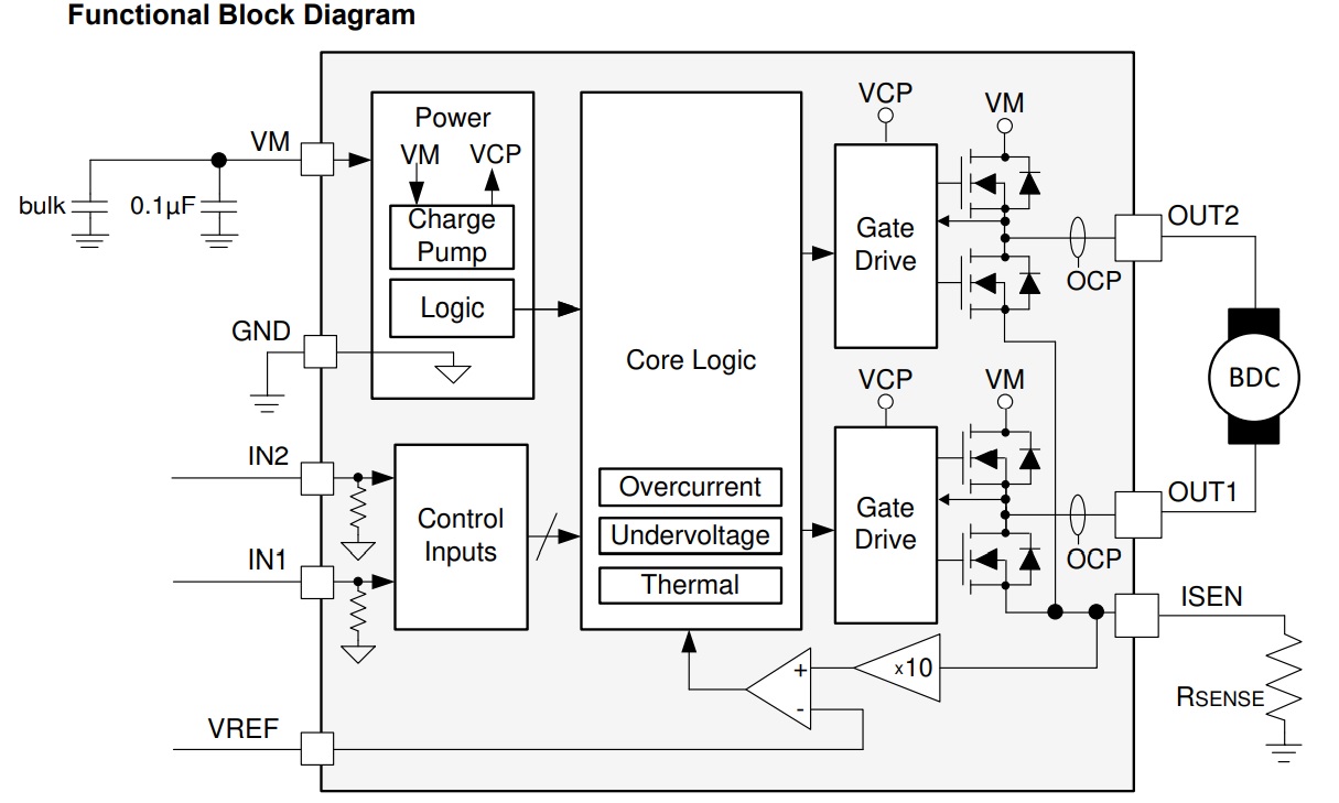
The DRV8251 device is an integrated motor driver with N-channel H-bridge, charge pump, current regulation, and protection circuitry. The charge pump improves efficiency by supporting N-channel MOSFET half bridges and 100% duty cycle driving. The DRV8251 implements a current regulation feature by comparing the analog input VREF and the voltage across a current-sense shunt resistor on the ISEN pin. The ability to limit current can significantly reduce large currents during motor start-up and stall conditions. A low-power sleep mode achieves ultra-low quiescent current draw by shutting down most of the internal circuitry. Internal protection features include supply undervoltage lockout, output overcurrent, and device overtemperature. The DRV8251 is part of a family of devices that come in pin-to-pin, scalable RDS(on) and supply voltage options to support various loads and supply rails with minimal design changes.
Current Regulation
The DRV8251 device limits the output current based on the analog input, VREF, and the resistance of an external sense resistor on the ISEN pin, RSENSE R4, according to Equation:
ITRIP =VREF/AV × RSENSE= VREF/10 × RSENSE
By using current regulation, the device input pins can be set for 100% duty cycle, while the device switches the outputs to keep the motor current at the ITRIP level. The default current limit is 2.1A, if VREF = 4 V and an RSENSE = 0.22 Ω, the DRV8251 limits motor current to 2.1 A during high torque conditions. Refer data sheet of the chip for guidelines on selecting a sense resistor. When ITRIP is reached, the device enforces slow current decay by enabling both low-side FETs, and it does this for a time of tOFF.
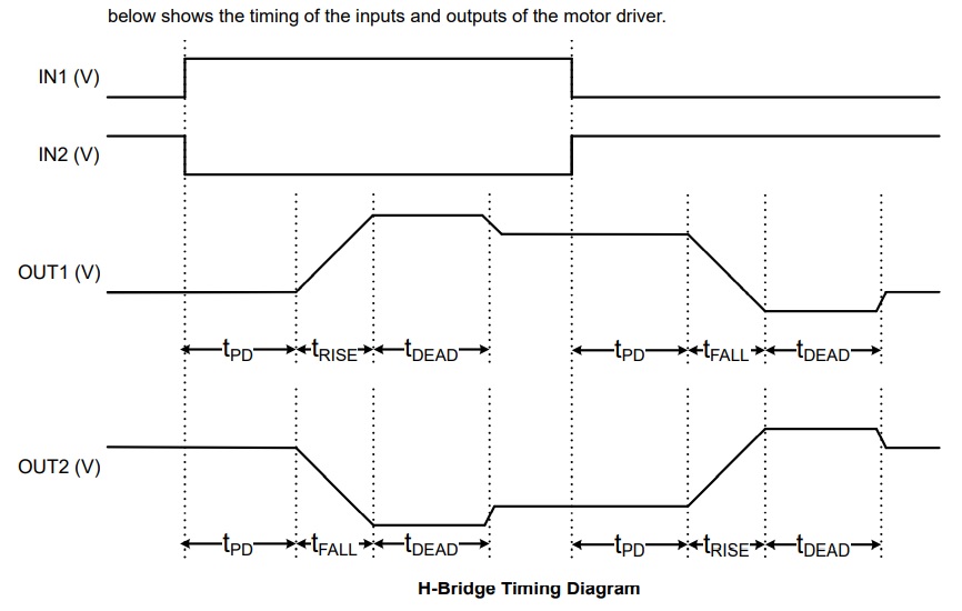
Inputs IN1 and IN2
The inputs can be set to static voltages for 100% duty cycle drive, or they can be pulse-width modulated (PWM) to variable motor speed. When using PWM, switching between driving and braking typically works best. For example, to drive a motor forward with 50% of the maximum RPM, IN1 = 1 and IN2 = 0 during the driving period, and IN1 = 1 and IN2 = 1 during the other period.
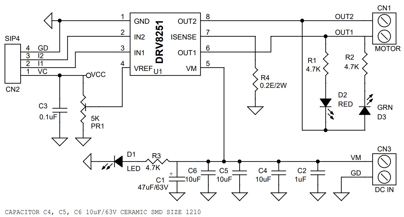
Schematic
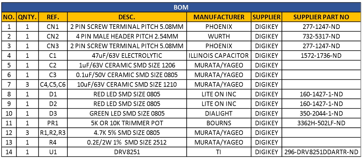
Parts List
| NO. | QNTY. | REF. | DESC. | MANUFACTURER | SUPPLIER | SUPPLIER PART NO |
|---|---|---|---|---|---|---|
| 1 | 1 | CN1 | 2 PIN SCREW TERMINAL PITCH 5.08MM | PHOENIX | DIGIKEY | 277-1247-ND |
| 2 | 1 | CN2 | 4 PIN MALE HEADER PITCH 2.54MM | WURTH | DIGIKEY | 732-5317-ND |
| 3 | 1 | CN3 | 2 PIN SCREW TERMINAL PITCH 5.08MM | PHOENIX | DIGIKEY | 277-1247-ND |
| 4 | 1 | C1 | 47uF/63V ELECTROLYTIC | ILLINOIS CAPACITOR | DIGIKEY | 1572-1736-ND |
| 5 | 1 | C2 | 1uF/63V CERAMIC SMD SIZE 1206 | MURATA/YAGEO | DIGIKEY | |
| 6 | 1 | C3 | 0.1uF/50V CERAMIC SMD SIZE 0805 | MURATA/YAGEO | DIGIKEY | |
| 7 | 3 | C4,C5,C6 | 10uF/63V CERAMIC SMD SIZE 1210 | MURATA/YAGEO | DIGIKEY | |
| 8 | 1 | D1 | RED LED SMD SIZE 0805 | LITE ON INC | DIGIKEY | 160-1427-1-ND |
| 9 | 1 | D2 | RED LED SMD SIZE 0805 | LITE ON INC | DIGIKEY | 160-1427-1-ND |
| 10 | 1 | D3 | GREEN LED SMD SIZE 0805 | DIALIGHT | DIGIKEY | 350-2044-1-ND |
| 11 | 1 | PR1 | 5K OR 10K TRIMMER POT | BOURNS | DIGIKEY | 3362H-502LF-ND |
| 12 | 3 | R1,R2,R3 | 4.7K 5% SMD SIZE 0805 | MURATA/YAGEO | DIGIKEY | |
| 13 | 1 | R4 | 0.2E/2W 1% SMD SIZE 2512 | MURATA/YAGEO | DIGIKEY | |
| 14 | 1 | U1 | DRV8251 | TI | DIGIKEY | 296-DRV8251DDARTR-ND |
Timing Diagram
Input Logic
Block Diagram
Connections
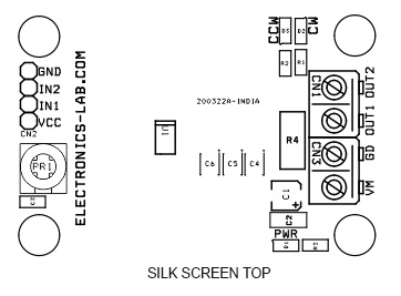
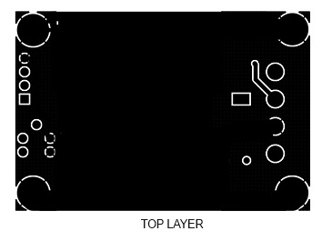
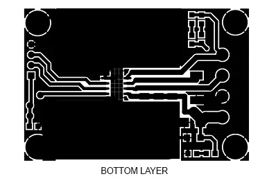
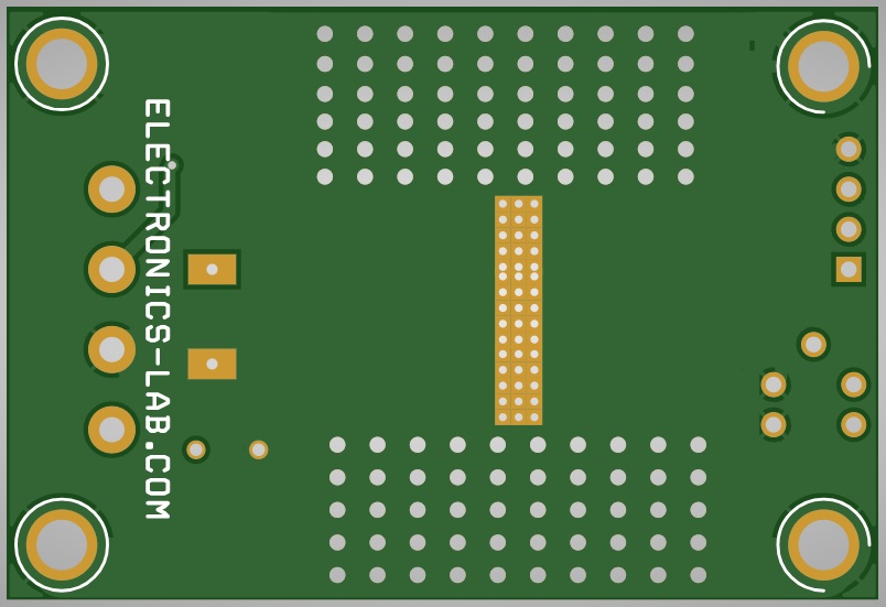
Gerber View
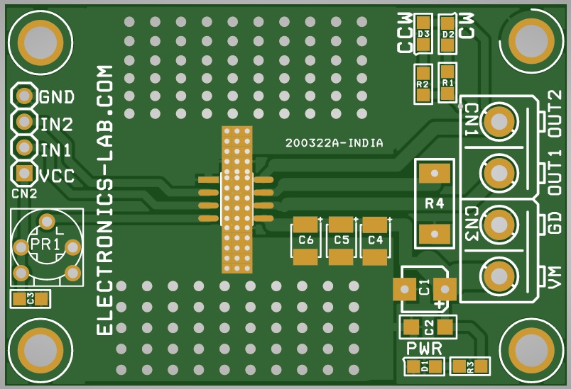
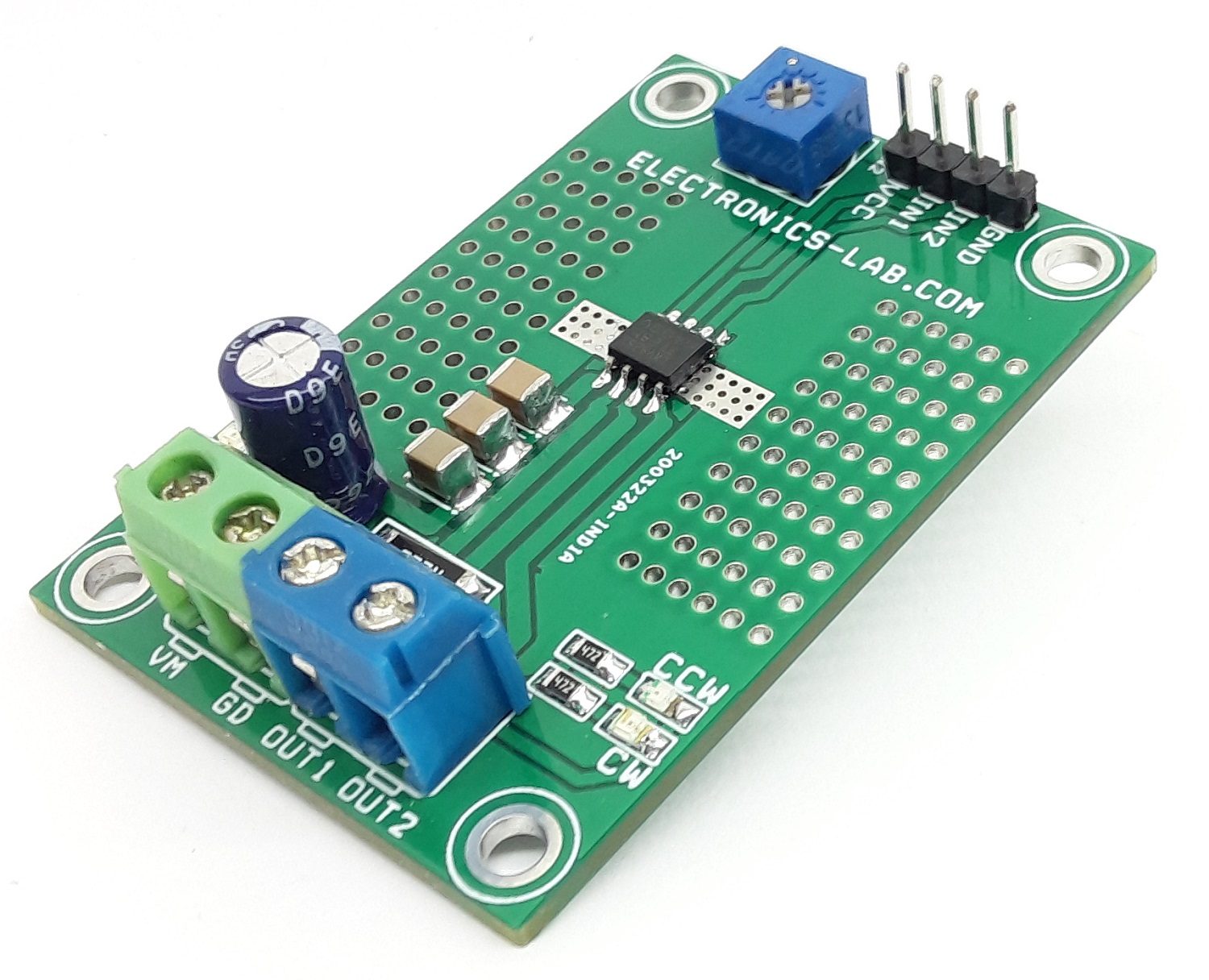
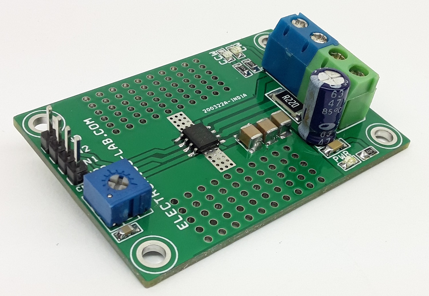
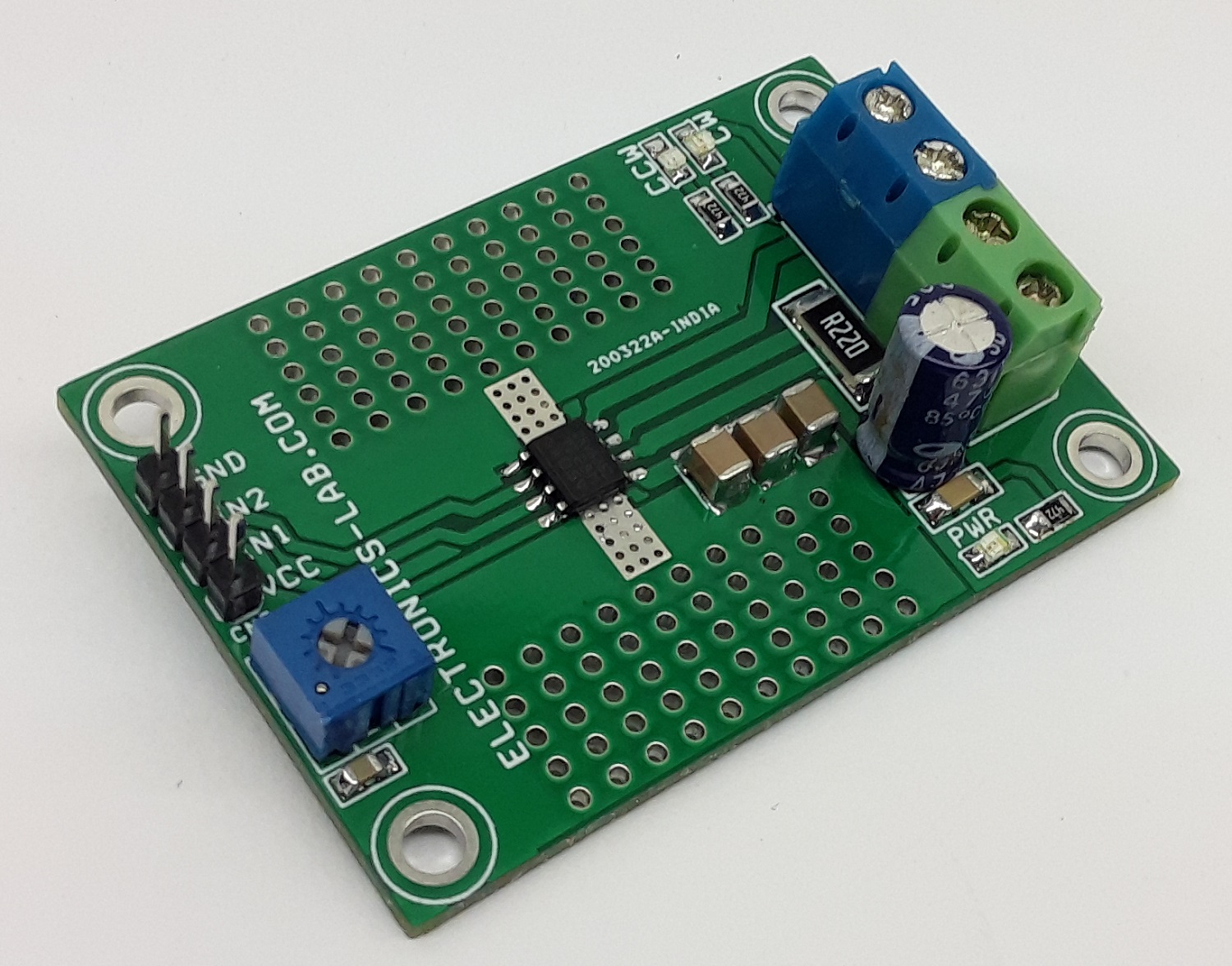
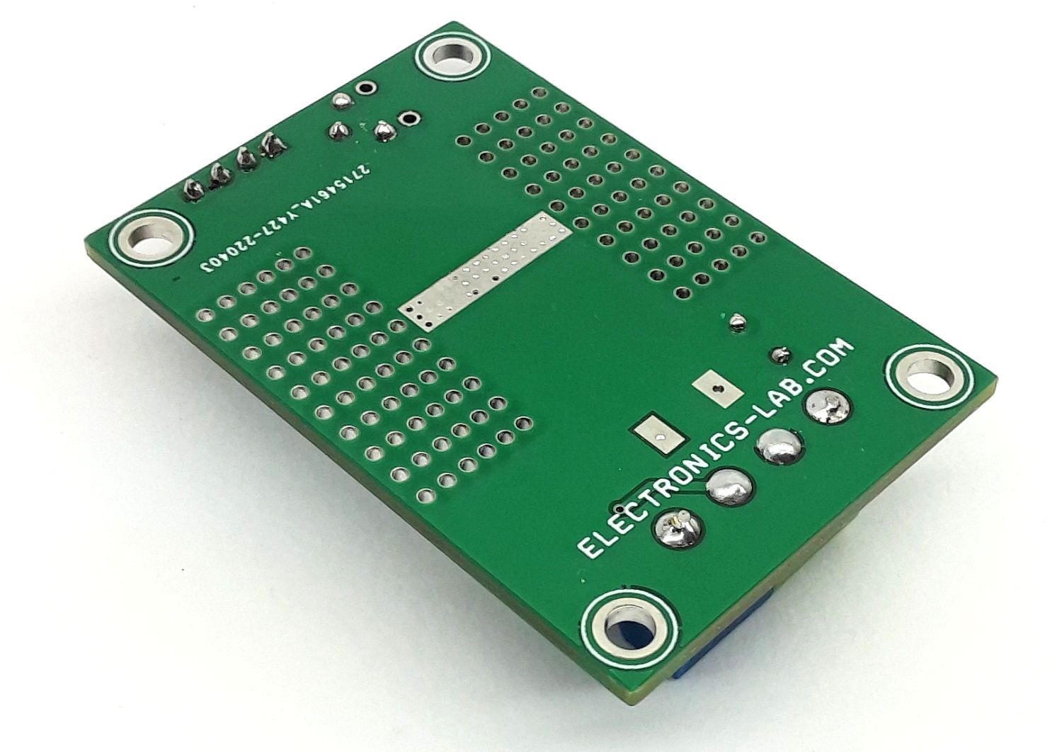
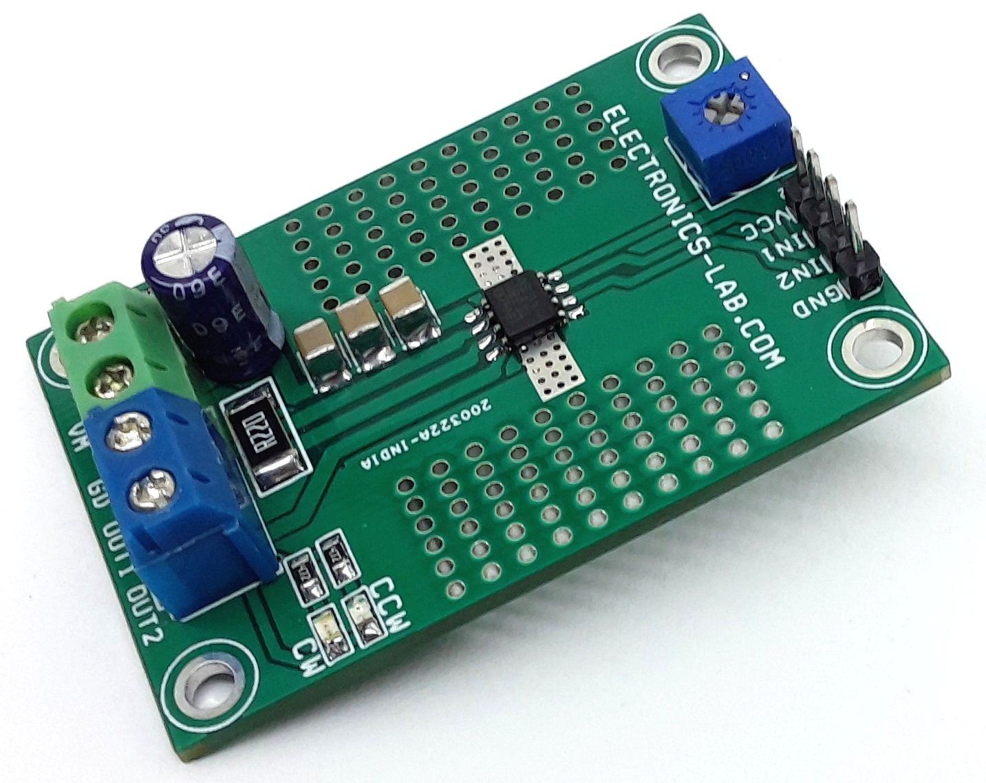
Photos
Video
DRV8251 Datasheet
PCB