

DC Motor & Direction Controller with Brake using MC33035
- Rajkumar Sharma
- 28.616 Views
- moderate
- Tested
- SKU: EL62796
- Quote Now
- 0 Likes

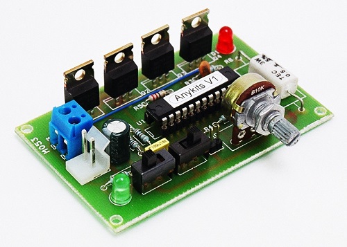
3AMP DC Motor speed and direction controller using MC33035 IC from on semiconductor, though the MC33035 was designed to control brushless DC motor , it may also be used to control DC brush type motors. MC33035 driving a Mosfets based H-Bridge affording minimal parts count to operate a brush type motor. On board potentiometer provided for speed control, slide switch for direction control and brake, On board jumper available to enable the chip. The controller function in normal manner with a PWM frequency of approximately 25Khz. Motor speed is controlled by adjusting the voltage presented to the non inverting input of the error amplifier establishing the PWM’s slice or reference level. Cycle by cycle current limiting of the motor is accomplished by sensing the voltage across the shunt resistor to the ground of H-bridge. The overcurrent sense circuit makes it possible to reverse the direction of the motor, using normal forward/reverse switch, on the fly and not have to completely stop it before reversing.
Specifications
- SUPPLY 12-18V DC
- Load Up to 3Amps, 5Amps with large size heat sink on Mosfets
- On Board Potentiometer for Speed Control
- Slide Switch ( SW1) for Brake
- Slide Switch (SW2) for Direction Control
- Jumper (J1) Provided to Enable the chip
- LED (D1) Fault Indicator
- LED (D2) Power Indicator
- CN1 , Supply 12-18V DC
- MG1 Motor Connections
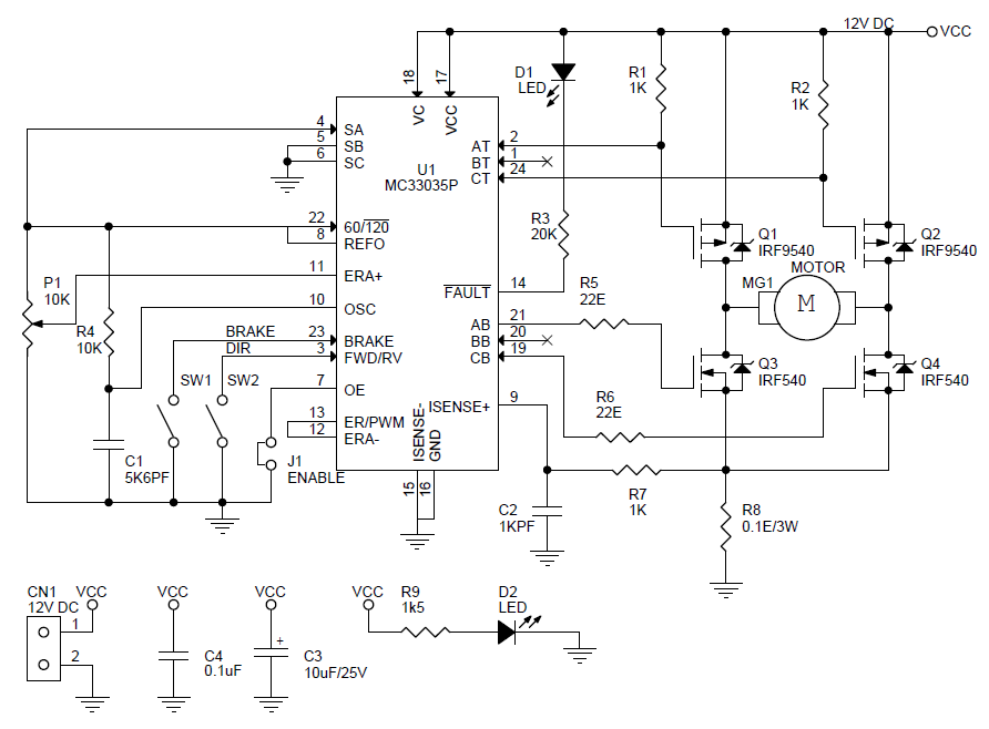
Schematic
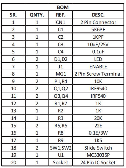
Parts List
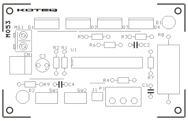
PCB


Nice circuit…. I’m looking for one that stops the motor if the shaft is locked (high current) and uses a momentary contact switch to enable forward or reverse. If opposite direction is switched while motor runs, motor stops, and requires another pulse to restart in either direction. Can this circuit be changed to suit or do you have another idea?
Check this project: https://www.electronics-lab.com/project/current-protection-switch/ It’s an overcurrent switch that energizes a relay when the current exceeds a predefined level.
when we completed the circuit then operate it and that time only D1 fault indicator is activated.
Please check for any of the following conditions: Invalid Sensor Input code, Enable Input at logic 0, Current Sense Input greater than 100 mV (Pin 9 with respect to Pin 15), Undervoltage Lockout activation, and Thermal Shutdown.
This circuit is not working….. challenge
Be sure to double check the parts placement and polarity and also check your circuit wiring if you build it on a breadboard. Otherwise we will need more info, so we can help.
Can you please provide the schematic for BLDC MOTOR….
Please post this on the community, so i can attach a schematic. https://www.electronics-lab.com/community/ Thanks