

Digital Potentiometer using Optical Encoder – 10KOhms
- Rajkumar Sharma
- 13.428 Views
- easy
- Tested
- SKU: EL63784
- Quote Now
- 0 Likes

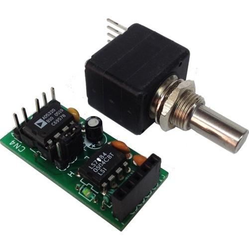
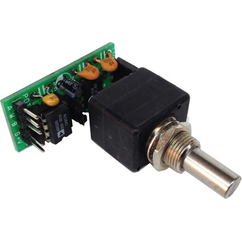
The primary application of the project is to replace the mechanical potentiometer with optical encoder which is long life, accurate, smooth in operation. The simple project has been designed around LS7184 quadrature clock converter IC from LSI semiconductor, AD5220-10 Digital potentiometer from Analog Devices, and optical encoder from Burns.
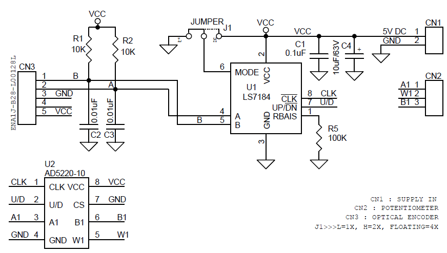
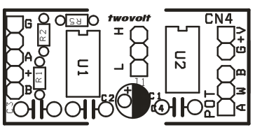
Quadrature clocks derived from optical encoder, when applied to the A and B inputs of the LS7184, are converted to strings of Clock and an Up/down direction control. These outputs interfaced directly to AD5220-10 Digital Potentiometer IC.
The AD5220-10 contains a single channel, 128 positions, and digitally-controlled 10K ohms variable resistor (VR) device. This device performs the same electronic adjustment function as a potentiometer.
Jumper J1 provided for scale of the 3-state input to select resolution x1, x2 or x4. The input quadrature clock rate is multiplied by factors of 1, 2 and 4 in x1, x2 and x4 mode, respectively, in producing the output UP/DN clocks. x1, x2 and x4 modes selected by the MODE input logic.
levels are as follows:
- Mode = 0 : x1 selected
- Mode = 1 : x2 selected
- Mode = Float : x4 selected
Features
- Supply 5V DC
- J1 Encoder pulse multiplication ( Jumper JL Close =1X, Jumper JH Close = X2, J1 Open = X4)
- Header Connector for Supply and Output
- Potentiometer Resistance 10K Ohms
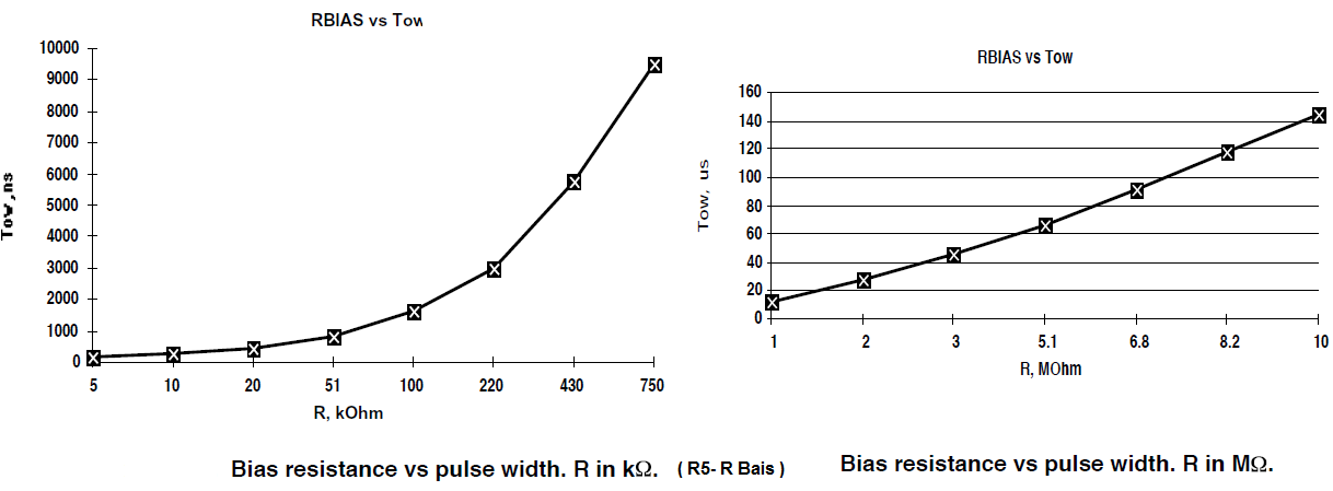
- R5 Resistor For Programmable output pulse width (200ns to 140μs) – Read Data Sheet
- X1 , X2 and X4 mode selection
- Excellent regulation of output pulse width
- On-chip filtering of inputs for optical or magnetic encoder applications.
- TTL compatible I/Os
Note : Input for external component connection. A Resistor (R5) connected between this input and VSS adjusts the output clock pulse width (Tow). Refer to graph for appropriate bias resistor value.
Schematic
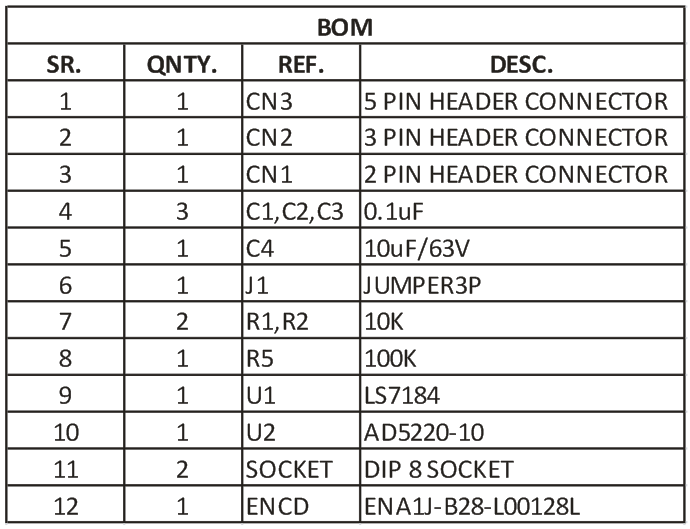
Parts List
Bias Resistor
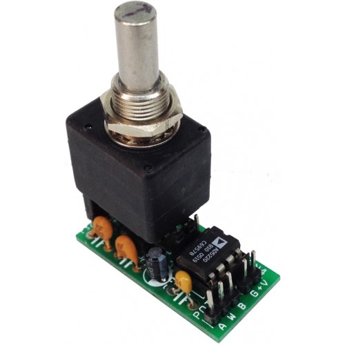
Photos
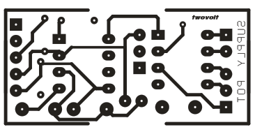
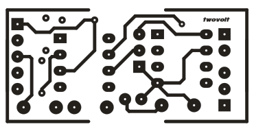
PCB


Can the potentiometer output of this circuit work for any voltage connected to the A1,W1,B1 terminals. All the digital potentiometer circuits and data sheets I can find on chips like the AD5220 say that the maximum you can connect to the “high pin” of the pot output can only be as high as the Vcc to the chip, which is limited to 5.5v. That makes it very hard to use these devices as true replacements for analog potentiometers, which are very often in circuits with higher voltages than that. Thank you.