H-Bridge Motor Driver with Integrated Current Sense and Regulation using DRV8874
In past, we have published many brushed dc motor driver boards for various projects and usually, they have some sort of limitations, as some of them are large in size, require large size heatsink, doesn’t have current feedback, they don’t have overload protection, some require external large size current shunt resistor and after all, recently we have found the amazing DRV8874 chip from Texas instruments that has some amazing features and protections features. It has a small package and can handle high current without a heatsink. We quickly become fans of this chip, and after a few tests and experiments, we are sharing this open-source module. This chip can be used with PWM/DIR input, PWM input, and 2 x Half-Bridge for dual motor control. We have tested this project with PWM/DIR inputs, and all inputs and outputs of the chip are accessible using the header connector. Refer to the datasheet of DRV8874 to explore other features and configure the board as per requirement. Example Arduino code is provided below.
Highlights
- Speed Control
- Direction Control
- Current Regulation/sense
- Over Current Trip
Features
- Motor Power Supply 4.5V to 24V (Maximum Input 37V DC)
- Load Current 0.5A/1A (3.7A Maximum)
- Peak Load Current 6 Amps
- PWM Frequency 10Khz to 20Khz
- PWM Duty Cycle 0-100%
- Proportional current output (IPROPI) 1.5V output when load current 0.5A
- No Heat-sink Required
- Trimmer Potentiometer to set Overload Protection
- Over Load Protection with I Trip
- Logic Supply 3.3V
- Required PWM and DIR signal
- Brake Function Available
- Undervoltage lockout (UVLO)
- Thermal shutdown (TSD)
- Automatic fault recovery
- All Input Signals 3.3V Voltage Level (Supports 1.8-V, 3.3-V, and 5-V logic inputs)
- Fault Output (Normally High 3.3V, Low when Fault Condition Occurs)
- Enable Input (High Input Enables, Low input Disables the output)
- PCB Dimensions 40.64 x 26.19 mm
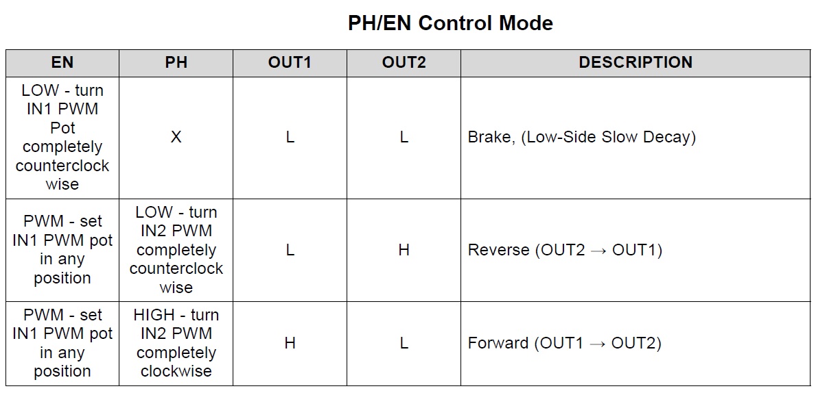
In the primary application example, we have configured and tested this project to drive bidirectional current through an external load (such as a brushed DC motor) using an H-bridge configuration. The H-bridge polarity and duty cycle are controlled with a PWM and I/O resource from an external controller like Arduino, connected to the EN/I1 (PWM) and PH/I2 (DIR) pins. The device is configured for the PH/EN control mode by tying the PMODE pin to GND. The current limit threshold (ITRIP) is generated with a trimmer potentiometer PR1 from the control logic supply voltage (3.3V). The device can be configured for the fixed off-time current regulation scheme by tying the IMODE pin to GND or Over current/Load output latched off by keeping this pin floating (Hi-Z). The load current is monitored with an ADC from the controller to detect the voltage across R2 RIPROPI. Current is set to 0.5A. Operating frequency 10 to 20Khz. PWM 0 to 100%.
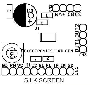
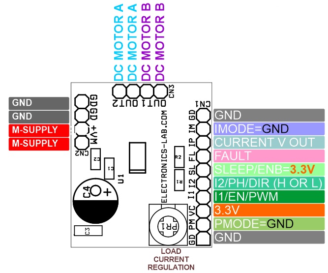
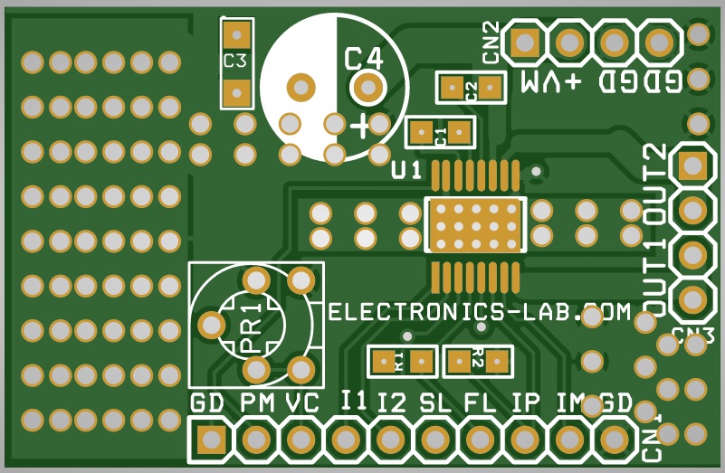
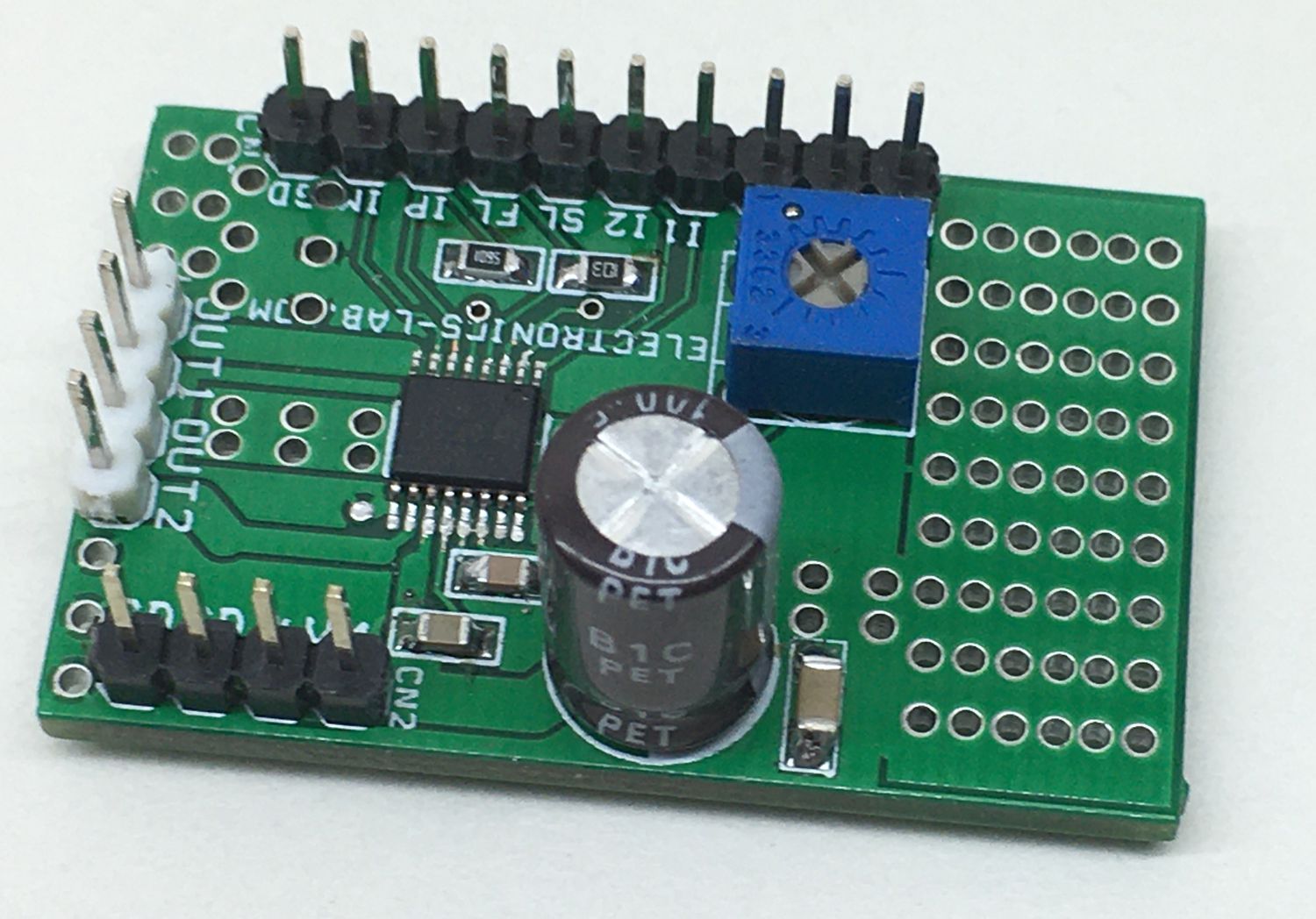
Following Signals/Inputs needed to control the motor for speed and direction type of interface (CN1 = 10 Pin Header Connector)
- Pin 1: GND
- Pin 2: PM, Connect this Pin to GND (Low Level signal/GND)
- Pin 3: VC (3.3V/100mA Logic Supply)
- Pin 4: I1 (PWM Input 0- 100% Duty Cycle, Frequency 10 to 20Khz)
- Pin 5: I2 (High or Low Level to Control the direction of the motor) High=3.3V, Low= GND
- Pin 6: SL (Sleep Mode, bringing this pin to Low, chip goes in sleep mode, High input enable the board) High=3.3V, Low = GND
- Pin 7: FL (Fault Output, this is an output pin normally high, goes low when fault condition occurs)
- Pin 8: IP (Motor Load Current Feedback output pin provides Analog voltage output to interface with ADC)
- Pin 9: IM (The device is configured for the fixed off-time current regulation scheme by tying the IMODE pin to GND)
- Pin10: GND
Testing the Board
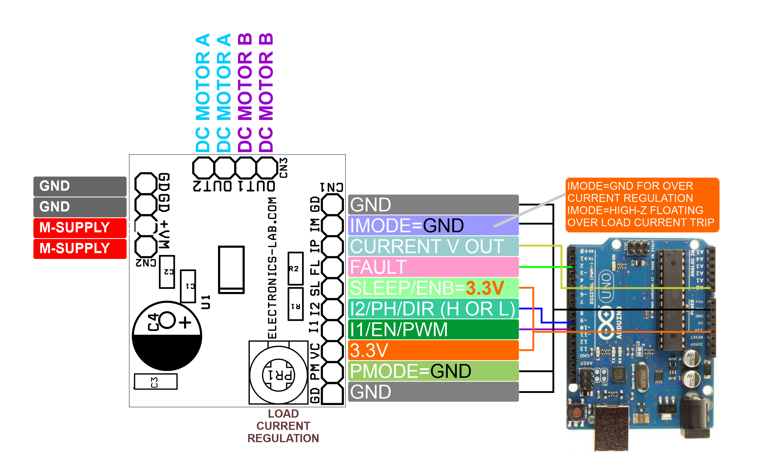
An example Arduino code is provided to test the board. The Arduino generates the PWM Signal and DIR signal. Check the connection diagram above and hook up all the connections accordingly. Set the I TRIP trimmer potentiometer in middle, connect the motor and power supply, the motor should move with half speed forward after 2 seconds reverse in a loop.
Arduino Digital pin D9 is connected to I2/PH/DIR, Arduino Digital Pin D10 is connected to I1/EN/PWM, SL-nSleep=3.3V, VC=3.3V, GND=GND, PMode=GND, IMODE=GND or Floating, Fault pin can be connected to any of digital pin of Arduino if required, Current feedback IP can be connected to the analog input of Arduino to measure the motor load current.
The VREF potentiometer PR1
Sets a reference voltage between 0V and 3.3 V. The IPROPI signal voltage will be proportional to the current out of the IPROPI pin. For more information on IPROPI, refer to the DRV8874 datasheet below. The current chopping threshold (ITRIP) is set through a combination of the VREF voltage (VVREF) and IPROPI output resistor R2 (RIPROPI). This is done by comparing the voltage drop across the external RIPROPI resistor to VVREF with an internal comparator.
ITRIP (A) x AIPROPI (μA/A) = VVREF (V) / RIPROPI (Ω)
For example:
- If VVREF = 2.5 V, RIPROPI = 5.6K Ohms, and AIPROPI = 450 μA/A, then ITRIP approximately 0.5 A.
- If VVREF = 2.5 V, RIPROPI = 1.5K Ohms, and AIPROPI = 450 μA/A, then ITRIP approximately 3.7 A.
IMODE Pin (IM pin 9, CN5)
IMODE PIN: Leaving the pin floating (Hi-Z), outputs latched offs when overcurrent condition occurs
IMODE PIN: Low/GND This allows the devices to limit the output current in case of the motor stall, high torque, or other high current load events.
This project can be configured in various ways (Refer DRV8874 for More Info)
- PMODE Functions, Logic Low=PWM/DIR,
- Logic High=PWM,
- Open/Floating High-Z= Two Independent Half-Bridge
DRV8874 – 37-V, 6-A H-bridge motor driver with integrated current sensing & feedback
Current Sense and Regulation
Devices integrate current sensing, regulation, and feedback. These features allow for the device to sense the output current without an external sense resistor or sense circuitry reducing system size, cost, and complexity. This also allows for the devices to limit the output current in the case of motor stall or high torque events and give detailed feedback to the controller about the load current through a current proportional output.
The IPROPI pin outputs an analog current proportional to the current flowing through the low-side power MOSFETs in the H-bridge scaled by AIPROPI. The IPROPI output current can be calculated by Equation 1. The ILSx in Equation 1 is only valid when the current flows from drain to source in the low-side MOSFET. If current flows from source to drain, the value of ILSx for that channel is zero. For instance, if the bridge is in the brake, slow-decay state, then the current out of IPROPI is only proportional to the current in one of the low-side MOSFETs. IPROPI (μA) = (ILS1 + ILS2) (A) x AIPROPI (μA/A) (1) The current is measured by an internal current mirror architecture that removes the needs for an external power sense resistor. Additionally, the current mirror architecture allows for the motor winding current to be sensed in both the drive and brake low-side slow-decay periods allowing for continuous current monitoring in typical
bidirectional brushed DC motor applications. In coast mode, the current is freewheeling and cannot be sensed because it flows from source to drain. However, the current can be sampled by briefly reenabling the driver in either drive or slow-decay modes and measuring the current before switching back to coast mode again. In the case of independent PWM mode and both low-side MOSFETs are carrying current, the IPROPI output will be the sum of the two low-side MOSFET currents. The IPROPI pin should be connected to an external resistor (RIPROPI) to ground in order to generate a proportional voltage (VIPROPI) on the IPROPI pin with the IIPROPI analog current output. This allows for the load current to be measured as the voltage drop across the RIPROPI resistor with a standard analog to digital converter (ADC). The RIPROPI resistor can be sized based on the expected load current in the application so that the full range of the controller ADC is utilized. Additionally, the DRV887x-Q1 devices implement an internal IPROPI voltage clamp circuit to limit VIPROPI with respect to VVREF on the VREF pin and protect the external ADC in case of output overcurrent or unexpected high current events. The corresponding IPROPI voltage to the output current can be calculated by Equation VIPROPI (V) = IPROPI (A) x RIPROPI (Ω)
Current Regulation
The DRV887x-Q1 family of devices integrate current regulation using either a fixed off-time or cycle-by-cycle PWM current chopping scheme. The current chopping scheme is selectable through the IMODE quad-level input. This allows the devices to limit the output current in case of motor stall, high torque, or other high current load events. The IMODE level can be set by leaving the pin floating (Hi-Z), connecting the pin to GND, or connecting a resistor between IMODE and GND. The IMODE pin state is latched when the device is enabled through the nSLEEP pin. The IMODE state can be changed by taking the nSLEEP pin logic low, waiting the tSLEEP time, changing the IMODE pin input, and then enabling the device by taking the nSLEEP pin back logic high. The IMODE input is also used to select the device response to an overcurrent event. See more details in the Protection Circuits section refer data sheet.
The internal current regulation can be disabled by tying IPROPI to GND and setting the VREF pin voltage greater than GND (if current feedback is not required). If current feedback is required and current regulation is not required, set VVREF and RIPROPI such that VIPROPI never reaches the VVREF threshold. For proper operation of the current regulation circuit, VVREF must be within the range of the VREF pin specified in the Recommended Operating Conditions table. In independent half-bridge control mode (PMODE = Hi-Z), the internal current regulation is automatically disabled since the outputs are operating independently and the current sense and regulation is shared between half-bridges.
The DRV8874-Q1 is an integrated motor driver with N-channel H-bridge, charge pump, current sensing and proportional output, current regulation, and protection circuitry. The charge pump improves efficiency by supporting N-channel MOSFET half bridges and 100% duty cycle driving. The family of devices come in pin-to-pin RDS (on) variants to support different loads with minimal design changes. An internal current mirror architecture on the IPROPI pin implements current sensing and regulation. This eliminates the need for a large power shunt resistor, saving board area and reducing system cost. The IPROPI current-sense output allows a microcontroller to detect motor stall or changes in load conditions. Using the external voltage reference pin, VREF, these devices can regulate the motor current during start-up and high-load events without interaction from a microcontroller. A low-power sleep mode achieves ultra-low quiescent current draw by shutting down most of the internal circuitry. Internal protection features include supply undervoltage lockout, charge pump undervoltage, output overcurrent, and device overtemperature. Fault conditions are indicated on nFAULT.
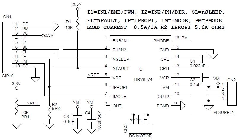
Schematic
Parts List
| SR. | QNTY. | REF. | DESC. | VENDOR/DIGIKEY/MOUSER |
|---|---|---|---|---|
| 1 | 1 | CN1 | 10 PIN MALE HEADER 2.54MM PITCH | DIGIKEY S1011EC-40-ND |
| 2 | 2 | CN2,CN3 | 4 PIN MALE HEADER 2.54MM PITCH | DIGIKEY S1011EC-40-ND |
| 3 | 1 | C1 | 0.022uF/50V SMD SIZE 0805 | YAGEO |
| 4 | 2 | C2,C3 | 0.1uF/50V SMD SIZE 0805 | YAGEO |
| 5 | 1 | C4 | 100uF/50V ELECTROLITIC | DIGIKEY P15369CT-ND |
| 6 | 1 | PR1 | 50K TRIMMER | DIGIKEY 3296W-503LF-ND |
| 7 | 1 | R1 | 10K 5% SMD SIZE 0805 | YAGEO |
| 8 | 1 | R2 | 5.6K 5% SMD SIZE 0805 | YAGEO |
| 9 | 1 | U1 | DRV8874 TEXAS INTRUMENTS | DIGIKEY 296-DRV8874PWPRCT-ND |
Connections
Truth Table
Fault table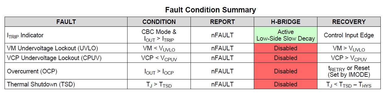
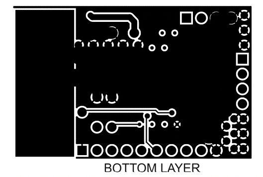
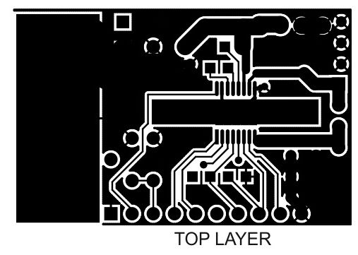
Gerber View
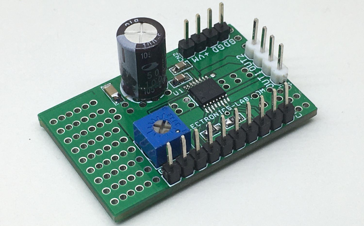
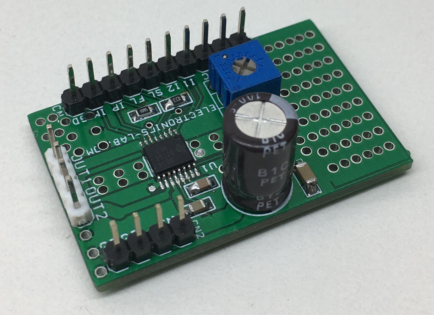
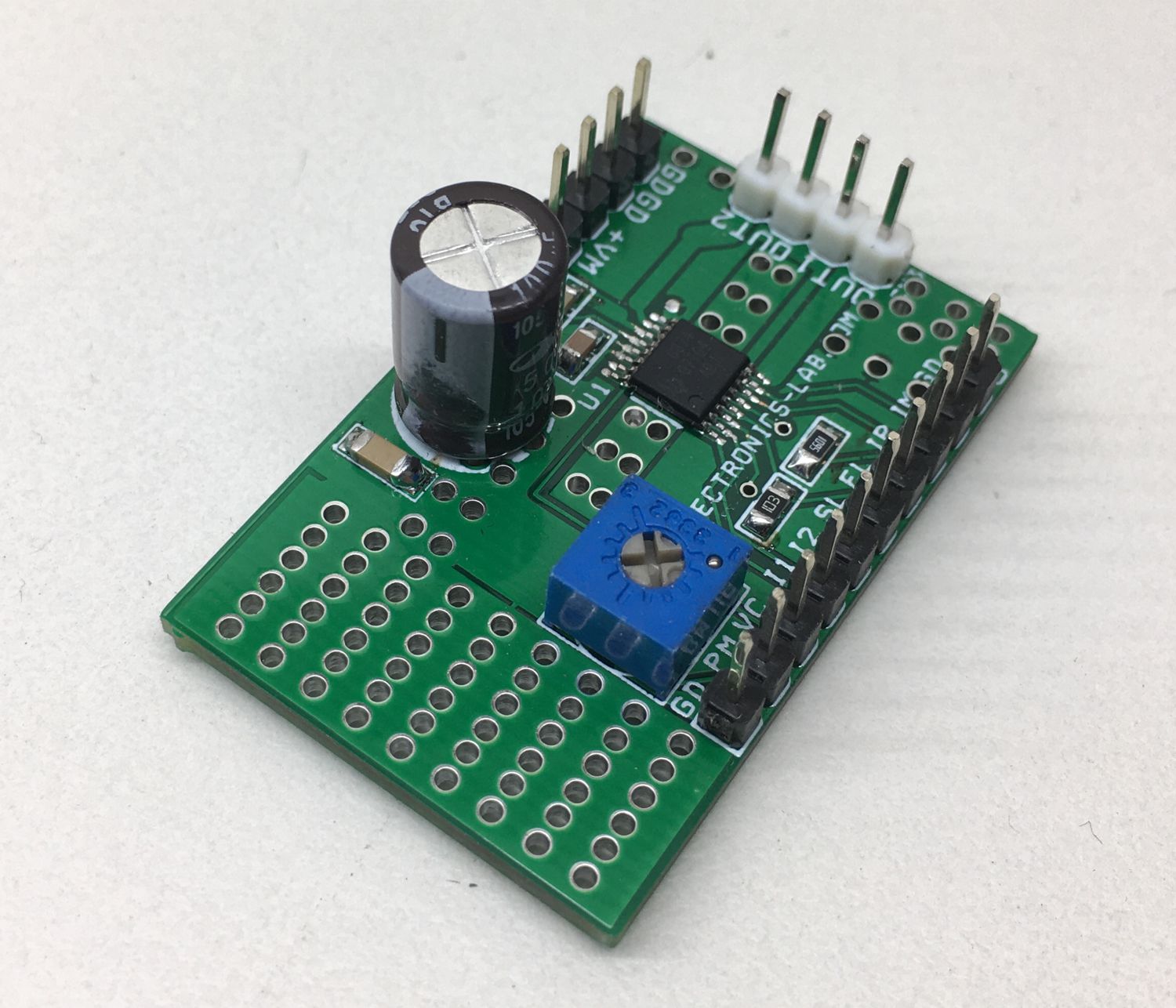
Photos
Video
DRV8874 Datasheet
PCB