

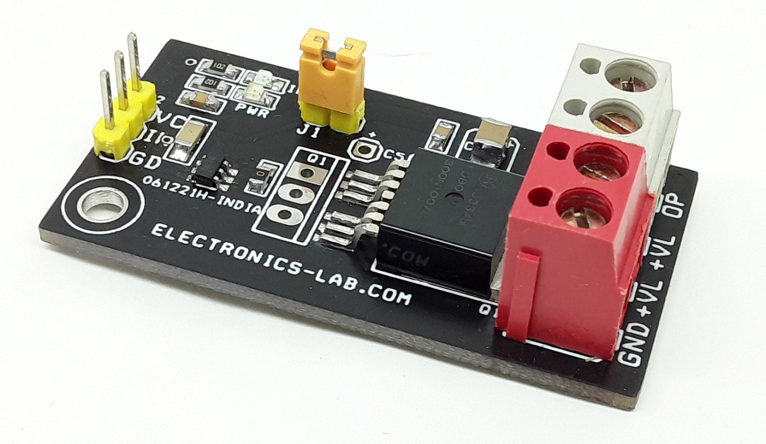
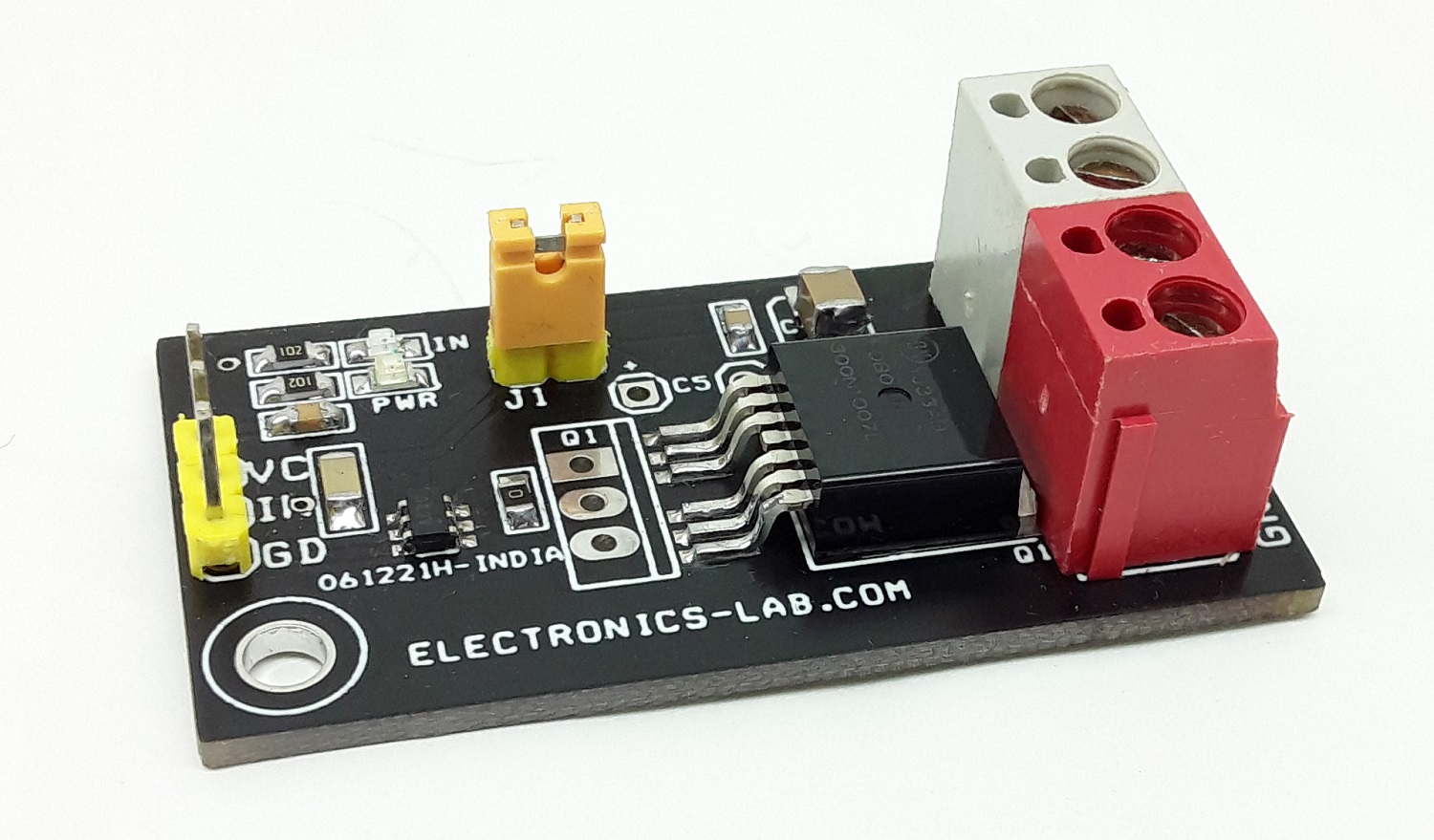
High Current MOSFET Based Power Switch with Gate Driver
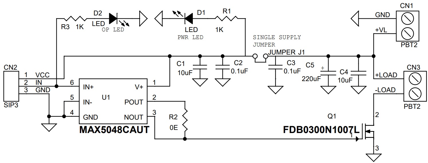
This power load switch project provides a simple and inexpensive method for power control. It is intended for driving a resistive or inductive load. A TTL logic signal from the system turns the load switch ON and OFF. The project consists of a low ohm N-Channel Power Trench MOSFET FDB0300N1007L and Gate driver MAX5048 chip. The load can be controlled by applying a PWM signal or Logic input.
The MAX5048A is a high-speed MOSFET driver capable of sinking/sourcing 7.6A/1.3A peak currents. These devices take logic input signals and drive a large external MOSFET. The MAX5048A has noninverting inputs that give the user greater flexibility in controlling the MOSFET. They feature two separate outputs working in a complementary mode, offering flexibility in controlling both turn-on and turn-off switching speeds.
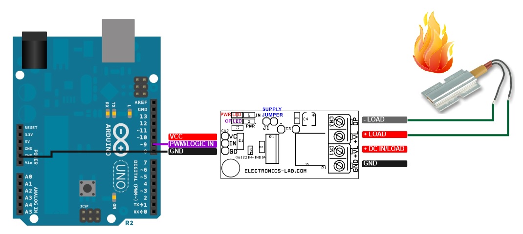
Arduino Interface
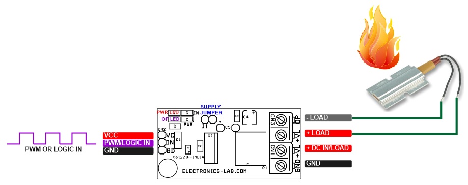
Sample Arduino code is provided below to drive and test the board with a PWM signal. Connections are as follows.
MOSFET FDB0300N1007L – N-Channel Power Trench 100V, 200Amps
- VGS 10V = 3 mΩ ID 26 Amps
- VGS 6V = 4.5 mΩ ID 20 Amps
Operating Power Supply – 5V to 12V
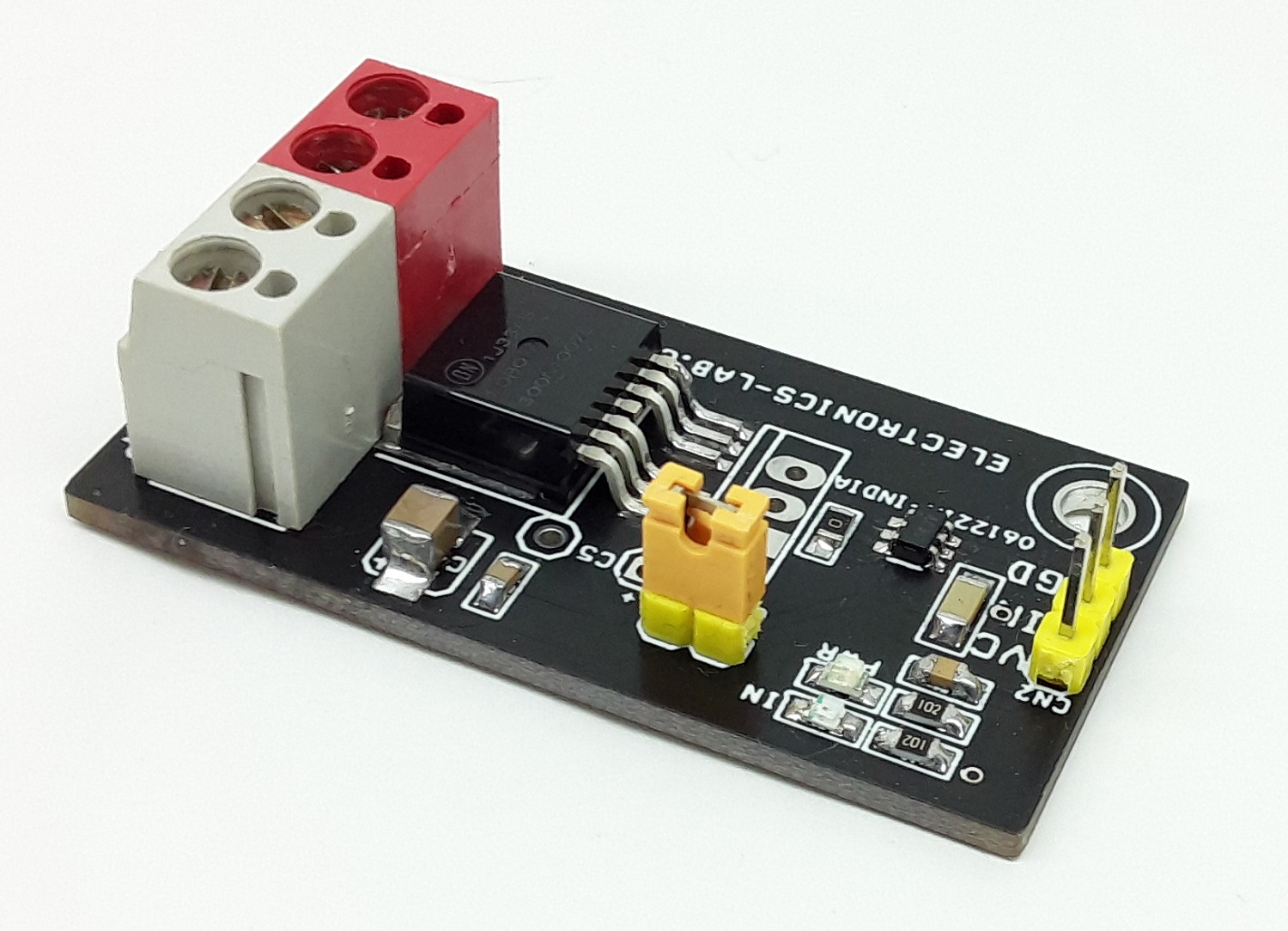
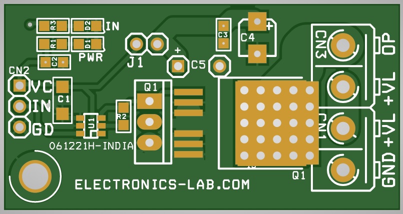
- Close Jumper J1
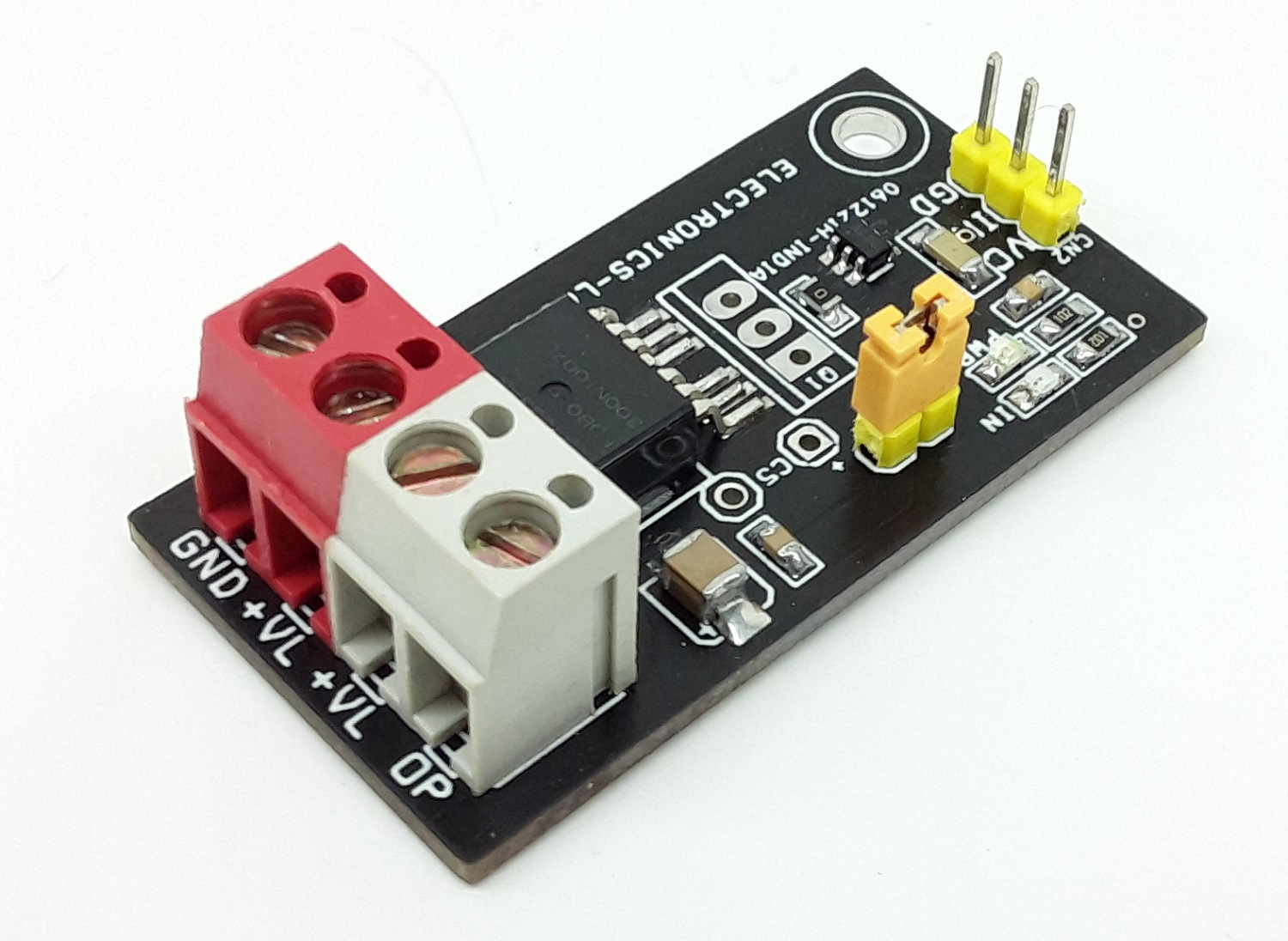
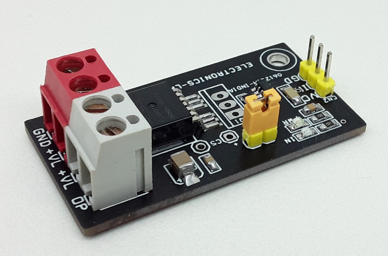
- CN2: Pin 2 PWM or Logic In, Pin 3 GND
- CN1: Load Supply 5V to 12V
- CN3: Load
- Capacitor C3 0.1uF/50V
- Capacitor C4 10uf-100uF 16V SMD Size 1210
- Capacitor C5 220uf/25V
Operating Power Supply – 12V to 60V
- Open Jumper J1
- CN2: Pin 1 Apply 12V VCC, Pin 2 PWM or Logic In, Pin 3 GND
- CN1: Load Supply 12V to 60V
- CN3: Load
- Do Not Install Capacitor C3
- Capacitor C4 1uf/75V SMD Size 1210
- Capacitor C5 Electrolytic 220uF-470uF/63V
Applications
- Heater Control
- High Current LED Dimmer or ON/OFF
- Solenoid
- DC Motors
- Power Management (High Current Power ON/OFF)
- Lamp Dimmer or Lamp ON/OFF Control
- Battery Protection Under/Over Voltage
- Under and Over Current Switch
Features
- Supply 5V to 12 V Single Supply Operation (Load 10 Amps Continues Without Fan, 15 Amps with Fan
- Supply 12V to 60V (Required Dual Supply for Load and Gate Driver) Load Up to 20Amps
- Input PWM or Logic 3.3V to 12V
- PWM Frequency Input up to 50Khz (Tested)
- PCB Dimensions 48.42 x 25.24 mm
Schematic
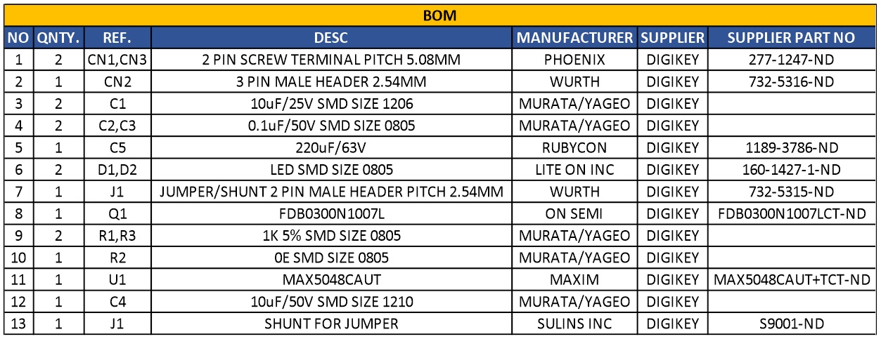
Parts List
| NO | QNTY. | REF. | DESC | MANUFACTURER | SUPPLIER | PART NO |
|---|---|---|---|---|---|---|
| 1 | 2 | CN1,CN3 | 2 PIN SCREW TERMINAL PITCH 5.08MM | PHOENIX | DIGIKEY | 277-1247-ND |
| 2 | 1 | CN2 | 3 PIN MALE HEADER 2.54MM | WURTH | DIGIKEY | 732-5316-ND |
| 3 | 2 | C1 | 10uF/25V SMD SIZE 1206 | MURATA/YAGEO | DIGIKEY | |
| 4 | 2 | C2,C3 | 0.1uF/50V SMD SIZE 0805 | MURATA/YAGEO | DIGIKEY | |
| 5 | 1 | C5 | 220uF/63V | RUBYCON | DIGIKEY | 1189-3786-ND |
| 6 | 2 | D1,D2 | LED SMD SIZE 0805 | LITE ON INC | DIGIKEY | 160-1427-1-ND |
| 7 | 1 | J1 | JUMPER/SHUNT 2 PIN MALE HEADER PITCH 2.54MM | WURTH | DIGIKEY | 732-5315-ND |
| 8 | 1 | Q1 | FDB0300N1007L | ON SEMI | DIGIKEY | FDB0300N1007LCT-ND |
| 9 | 2 | R1,R3 | 1K 5% SMD SIZE 0805 | MURATA/YAGEO | DIGIKEY | |
| 10 | 1 | R2 | 0E SMD SIZE 0805 | MURATA/YAGEO | DIGIKEY | |
| 11 | 1 | U1 | MAX5048CAUT | MAXIM | DIGIKEY | MAX5048CAUT+TCT-ND |
| 12 | 1 | C4 | 10uF/50V SMD SIZE 1210 | MURATA/YAGEO | DIGIKEY | |
| 13 | 1 | J1 | SHUNT FOR JUMPER J1 | SULINS INC | DIGIKEY | S9001-ND |
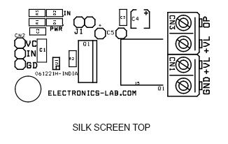
Connections
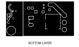
Gerber View
Photos


Video
MAX5048 Datasheet
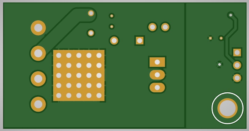
PCB


 Remote")

