

IR Remote Controlled Motorized Potentiometer – Arduino Compatible
- Rajkumar Sharma
- 1.938 Views
- moderate
- Tested
- SKU: EL112878
- Quote Now
- 0 Likes

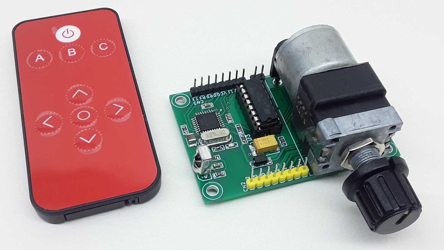
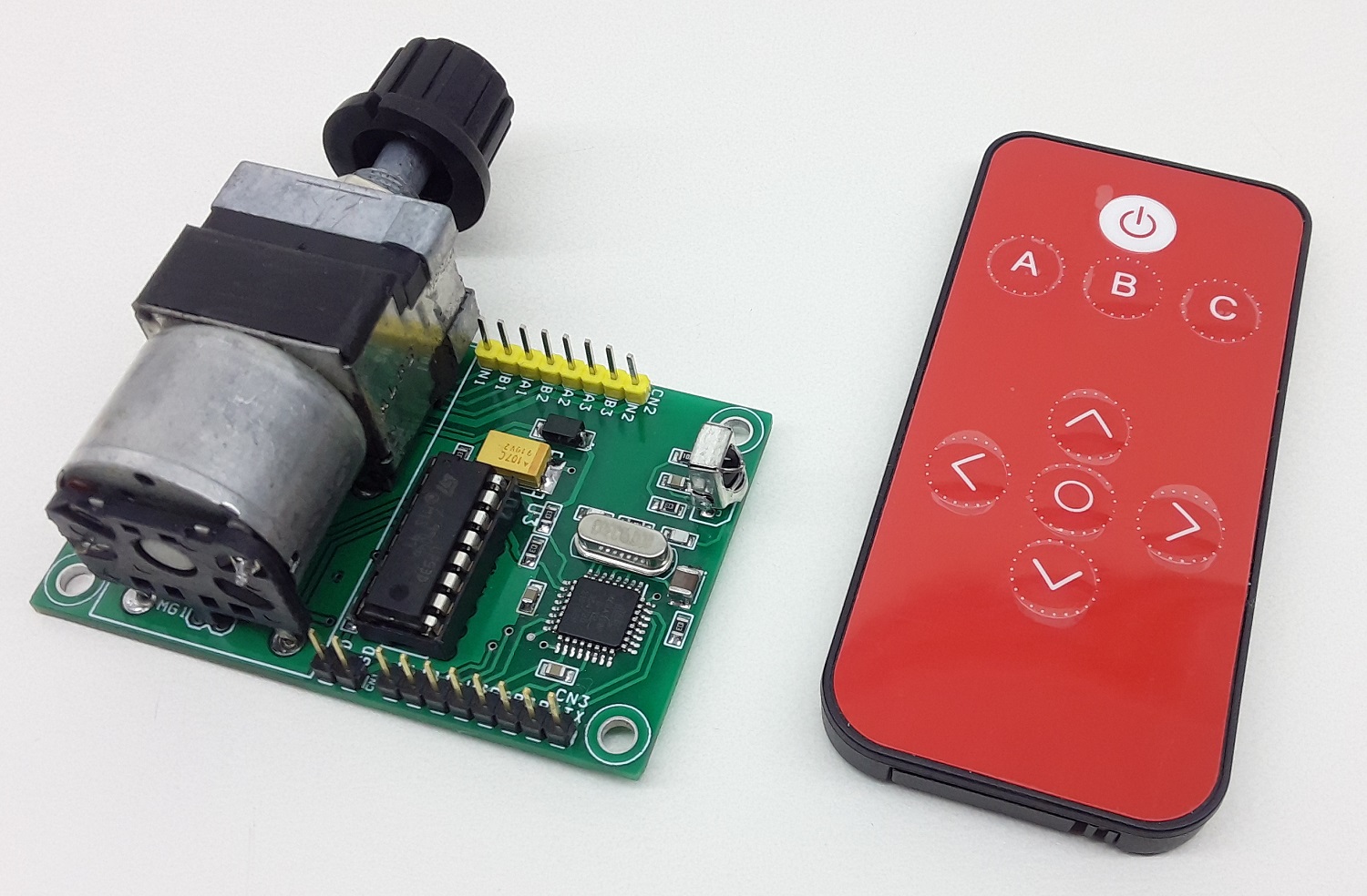
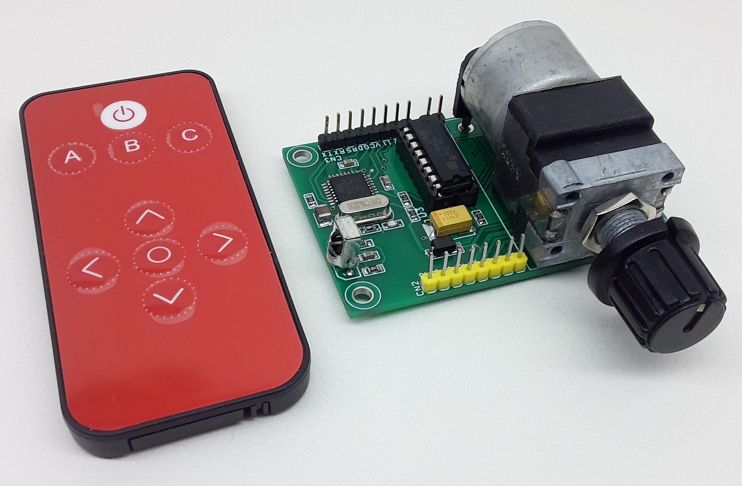
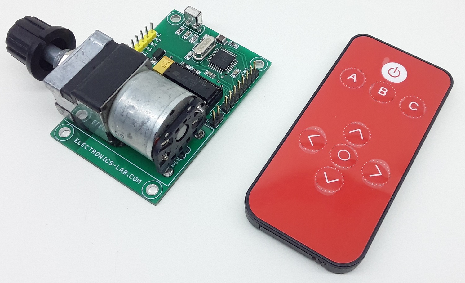
This is an Infrared Remote controlled motorized potentiometer controller. It’s an open-source project built on the Arduino platform and compatible with Arduino IDE for custom programming. The project consists ATMEGA328 microcontroller, IR sensor, L293D motor driver, ALPS Motorized potentiometer, a connector for Arduino programming, etc. The L293D H-bridge drives the potentiometer motor, 2 Parallel direction pins are used to change the motor direction which moves the POT in a forward or reverse direction.
Note: Motorized Potentiometers are built with a highly reliable linear potentiometer, with a slip clutch, geartrain, and motor in a single panel mount assembly which can be manually adjusted.
Arduino Pins
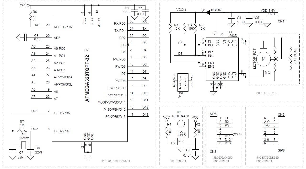
- Digital Pin D2 >> IR Sensor,
- Digital Pin D5 >>Motor Direction IN1+IN3,
- Digital Pin D6 >> Motor Direction IN2+IN4
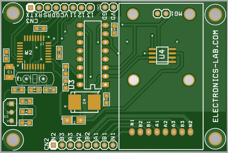
Components
- U1 IR Sensor
- U2 ATMEGA328 Micro-controller
- U3 Motor Driver
- CN3 Programming Connector
- CN2 Potentiometer Connection
- CN1 Power Input 5 To 6V
Arduino Code and IR Remote
- Arduino Code is available as a download below
- Switch A and Switch C of IR Remote Controls Motor Direction.
- User May modify this code as per requirement
- The project is compatible with Spark fun IR Remote COM-1489.
- Any IR Remote with 38Khz frequency will work with this project
More info about Spark fun IR Remote
Any IR Remote Can work with this project, to learn more….
- https://randomnerdtutorials.com/arduino-ir-remote-control
- https://www.maxphi.com/ir-remote-control-decoder-using-arduino
- https://learn.adafruit.com/using-an-infrared-library/hardware-needed
- https://create.arduino.cc/projecthub/opilitex/ir-decoder-using-irremote-h-v3-0-1-2bcae2
Programming the project with Arduino IDE
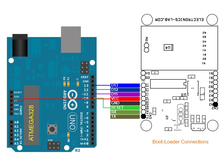
Use CN3 for Boot-Loader & Arduino Programming. More details here:
Bootloader Programming Connections
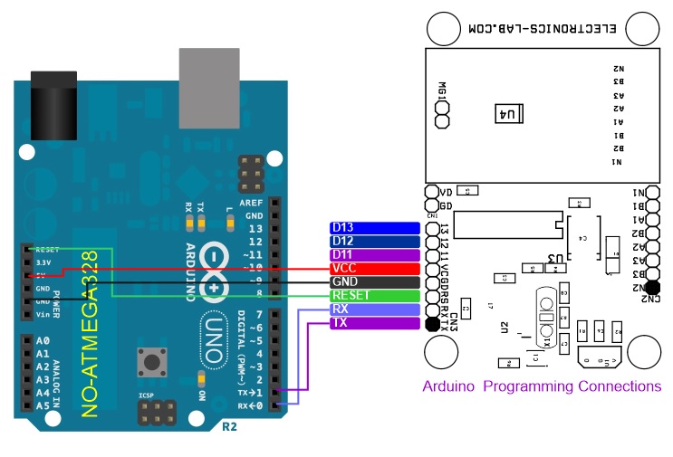
Code Upload Connections
Features
- Supply Input 5-6V DC @ 100mA
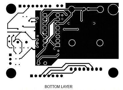
- PCB Dimensions 67.47 x 44.77 mm
Schematic
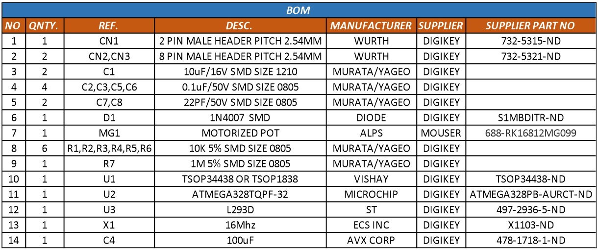
Parts List
| NO | QNTY. | REF. | DESC. | MANUFACTURER | SUPPLIER | SUPPLIER PART NO |
|---|---|---|---|---|---|---|
| 1 | 1 | CN1 | 2 PIN MALE HEADER PITCH 2.54MM | WURTH | DIGIKEY | 732-5315-ND |
| 2 | 2 | CN2,CN3 | 8 PIN MALE HEADER PITCH 2.54MM | WURTH | DIGIKEY | 732-5321-ND |
| 3 | 2 | C1 | 10uF/16V SMD SIZE 1210 | MURATA/YAGEO | DIGIKEY | |
| 4 | 4 | C2,C3,C5,C6 | 0.1uF/50V SMD SIZE 0805 | MURATA/YAGEO | DIGIKEY | |
| 5 | 2 | C7,C8 | 22PF/50V SMD SIZE 0805 | MURATA/YAGEO | DIGIKEY | |
| 6 | 1 | D1 | 1N4007 SMD | DIODE | DIGIKEY | S1MBDITR-ND |
| 7 | 1 | MG1 | MOTORIZED POT | ALPS | MOUSER | 688-RK16812MG099 |
| 8 | 6 | R1,R2,R3,R4,R5,R6 | 10K 5% SMD SIZE 0805 | MURATA/YAGEO | DIGIKEY | |
| 9 | 1 | R7 | 1M 5% SMD SIZE 0805 | MURATA/YAGEO | DIGIKEY | |
| 10 | 1 | U1 | TSOP34438 OR TSOP1838 | VISHAY | DIGIKEY | TSOP34438-ND |
| 11 | 1 | U2 | ATMEGA328TQPF-32 | MICROCHIP | DIGIKEY | ATMEGA328PB-AURCT-ND |
| 12 | 1 | U3 | L293D | ST | DIGIKEY | 497-2936-5-ND |
| 13 | 1 | X1 | 16Mhz | ECS INC | DIGIKEY | X1103-ND |
| 14 | 1 | C4 | 100uF | AVX CORP | DIGIKEY | 478-1718-1-ND |
| 15 | 1 | U4 - OPTIONAL | SiP2100 | Vishay | DIGIKEY | SIP2100DY-T1-GE3CT-ND |
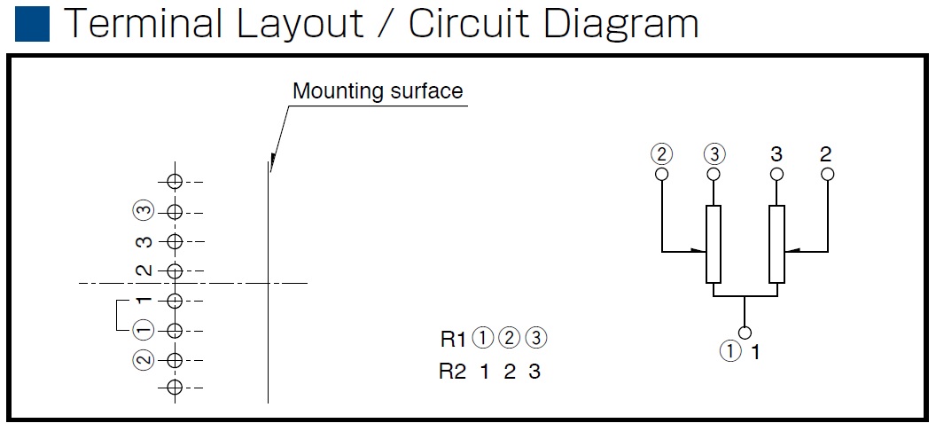
Connections
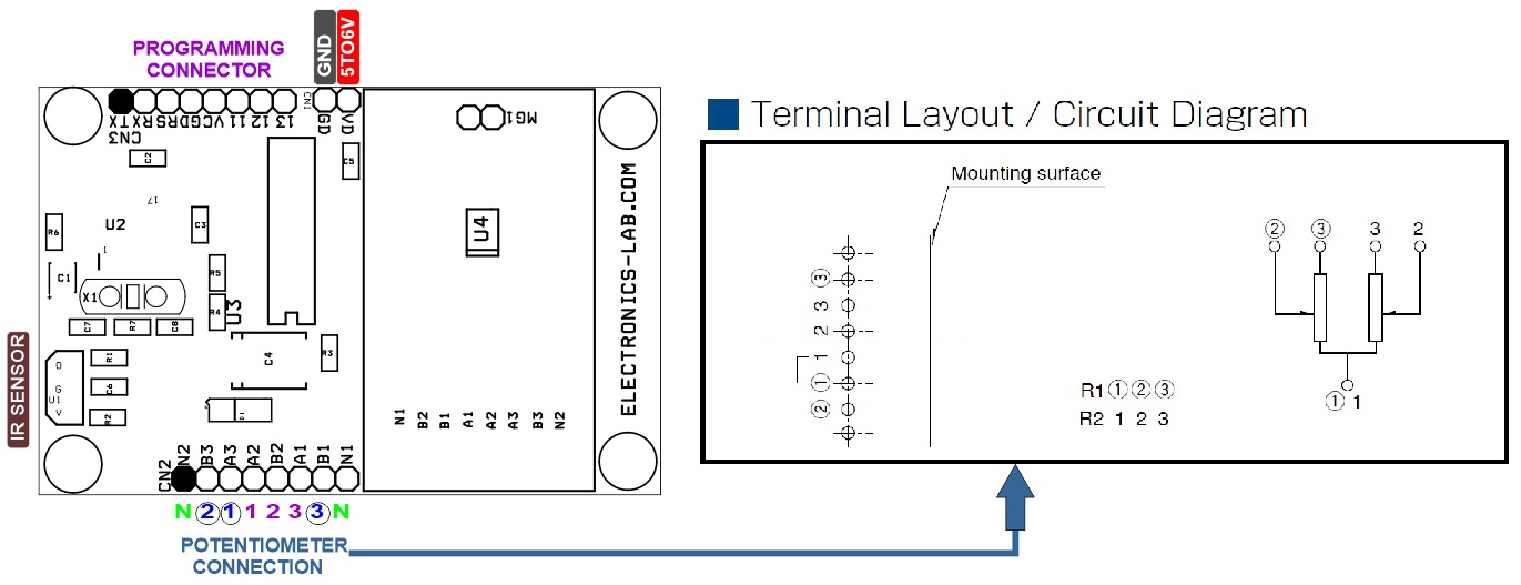
Potentiometer Layout
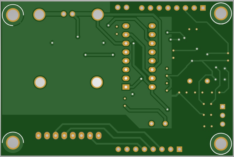
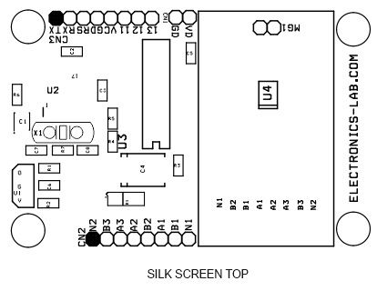
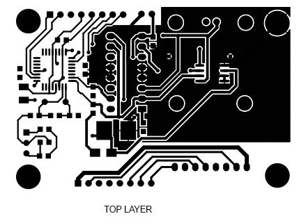
Gerber View
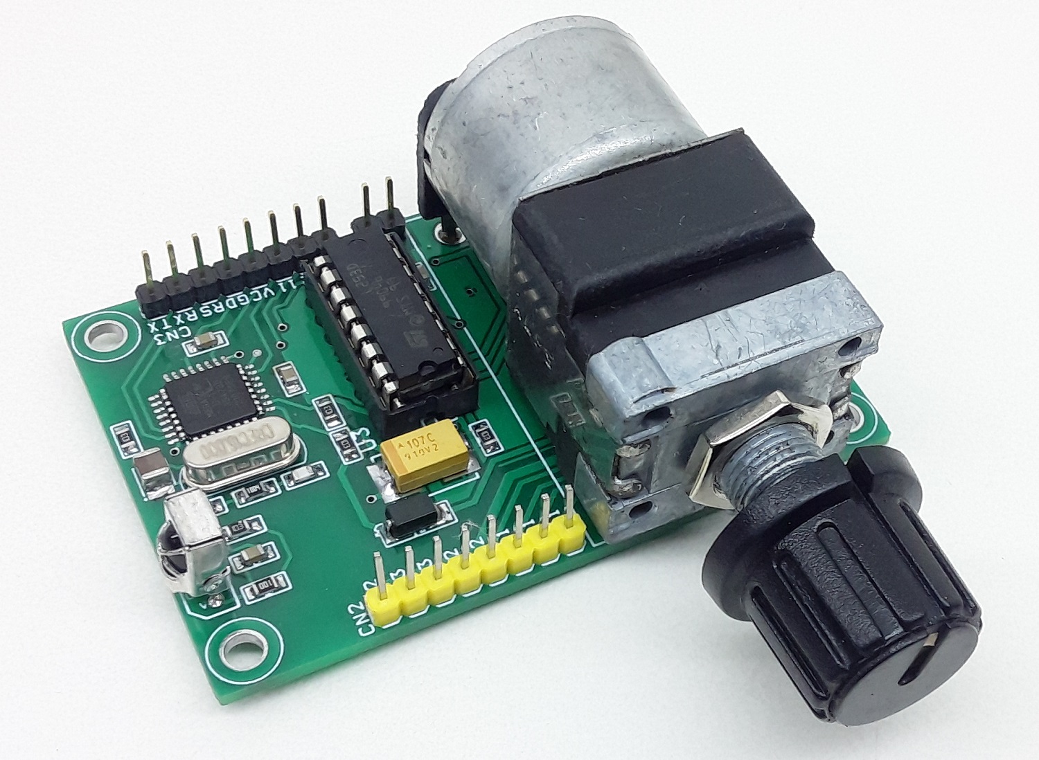
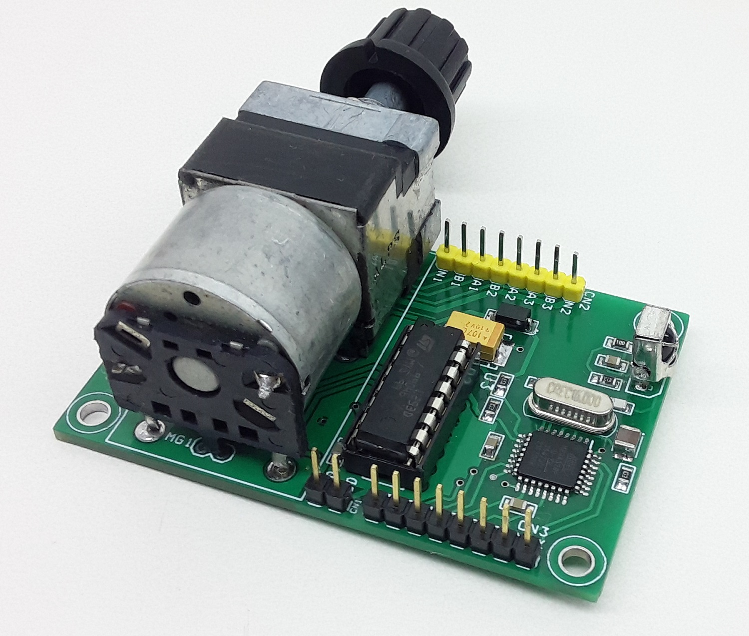
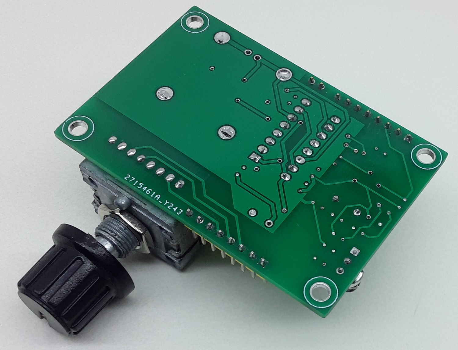
Photos
Video
L293D Datasheet
Please follow and like us:
PCB


Hello,
What is the part U4 on the motor pot side of the pcb?
Regards,
George
I believe I’ve found the answer for U4. It’s listed as DNP, do not populate, on the schematic so there is no part used there.
It’s an optional H-Bridge Chip (SIP2100DY-T1-GE3) used to drive other motors. You may not place it as it was populated for test purposes of the board. Hope it’s more clear now.
Updated the BOM
Thanks.
Hi Mike,
I found a discrepancy in the parts list regarding C4. The part number listed is for a 47uF cap instead of the specified 100uF.
Also, while studying the process of burning the bootloader and uploading the tested code, the code wouldn’t verify because of the line irrecv.blink13(true); I commented that line out and the code verified with no errors. Any suggestions ?
George
C4 is a filter capacitor and a value of 100nF would work fine. Regarding the code, i need to check deeper.
I was making a mistake adding the code file. It now verifies just fine. I will test the project tomorrow.
George
Well, I thought I had uploading the code file figured out, but apparently not. If I copy the contents of the TESTED CODE.txt into a blank Arduino sketch and try to verify I get this error message: ‘class IRrecv’ has no member named ‘blink13’
I was able to load the boot loader, but since I’m new at this, I’m making a mistake somewhere. Any help would be appreciated.
George
Hello,
very nice project.
I would like to try it and I need a little help please.
into the code, is this:
const int redPin = 10;
const int greenPin = 11;
and the Motor Driver has D5 and D6 coming from the microcontroller, which are the pins 9 and 10.
also, for the IR input:
const int RECV_PIN = 7;
IRrecv irrecv(RECV_PIN);
but, pin 7 is the OSC1
please be so kind and clarify how it is.
thank you.