

Programming Atmega328p Microcontroller with Arduino IDE
- Emmanuel Odunlade
- https://twitter.com/emmaodunlade
- emmaodunlade@gmail.com
- 64.784 Views
- moderate
- Tested
- 6 Likes

Introduction
Over the past few tutorials, we have mentioned several scenarios where using any of the Arduino board in a project may be an overkill due to the cost, size, and more technical reasons such as high power consumption. In the last tutorial, we discussed an alternative way of using Arduino, i.e. using the Atmega328p microcontroller alone which removes all the downsides of using the Arduino board, while retaining one of the biggest benefits of the Arduino platform; the ease of programming.
We covered details on preparing the Atmega328p microcontroller for programming by flashing the Arduino bootloader on Atmega328p and today’s tutorial will be a follow up to that tutorial, as we will look at how to program the boot-loaded Atmega328p microcontroller using the Arduino IDE.
The Atmega328p microcontroller, like any other microcontroller, can be quite tasking to use for a beginner. They usually require a certain set of tools, including a programmer (hardware), and a development platform (e.g Atmel Studio) for writing code. These development platforms, unlike the Arduino IDE usually require high knowledge of C or other programming languages, without the shortcuts and simplified functions which the Arduino provides.
To remove this difficulty, the microcontroller is flashed with the Arduino bootloader, which makes it ready for programming using the simpler and easy to use Arduino IDE.
To program the microcontroller using the Arduino IDE, the microcontroller must be connected via some sort of hardware to the computer. This is usually done via two major ways:
- Using a USB to Serial/TTL Adapter
- Using an Arduino board
Each of these approaches provides the microcontroller with an interface that enables interaction between the computer and the microcontroller.
We will take each of these approaches one after the other and look at the components and setup required to upload code to the microcontroller.
Using a USB to Serial/TTL Adapter
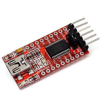
The first approach involves the connection of a USB to serial adapter to the microcontroller. The USB to Serial/TTL adapter converts data signals from the USB on the computer to serial/TTL for the microcontroller and vice versa. This enables communication from the microcontroller (serial) with the Arduino IDE running on the PC (USB). This setup, compared to the second one, is by far the cheapest, as these adapters are usually very cheap.
Required Components
The following components are required for this approach;
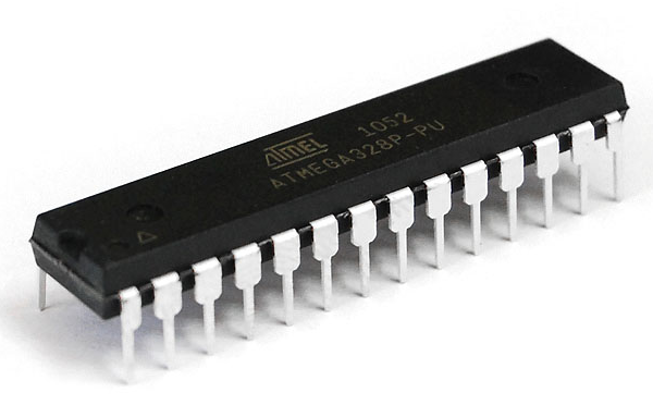
- Atmega328P microcontroller with the Arduino Bootloader installed
- Breadboard
- USB to serial/TTL Adapter
- 16MHz crystal oscillator
- 22pf capacitors x2
- 100nf capacitor
- Jumper Wires
- 100 ohms resistor
- LED
Schematic
Connect USB to Serial/TTL adapter to the microcontroller as shown in the schematics below. Don’t forget that this procedure will only work if the microcontroller has been flashed with a bootloader according to the procedure described in the last tutorial.
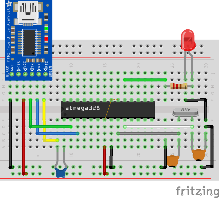
Most adapters can be configured to work at either 5v or 3.3v logic level. Ensure yours is configured to work on the 5v voltage level since supply to the microcontroller is 5v.
Uploading Code
Uploading code to the microcontroller after you are done with the connections, require no additional work asides, what you would have done if you where using an Arduino board. After typing in your code, select the port to which your adapter is connected, followed by the board type and hit the upload button. Upload takes only a few seconds, same as the Arduino board.
Note: when programming the Atmega328p MCU using the Arduino IDE, the matching board type you have to select is the “Arduino Duemilanove or Nano w/ ATmega328” board.
To test the setup, we will use the Arduino blink example. Select the example and click upload. You should see the connected LED start blinking after a while.
Using an Arduino Board
The second approach involves the use of an Arduino board in either of two similar ways;
- By replacing the microcontroller on the Arduino Uno with the one to be programmed
- By using any of the Arduino boards as an In-system programmer.
The first mode is the easiest way to upload code to the microcontroller, as it involves just replacing the microcontroller on the Uno, with the one to be programmed. However, this may not be the best when prototyping as the move of the chip from the Arduino to the project, back and forth, could lead to the pins of the microcontroller being damaged. Another downside to this is that it only works with the Arduino Uno as all other Arduino boards, use SMD type of microcontrollers which makes replacement impractical and development, expensive.
So no schematic for this, just swap the microcontroller and hit upload.
The second method involves the use of the Arduino Uno as an In-system programmer.
Required components
To use this approach, you will need the following components;
- Arduino Uno
- Breadboard
- USB to serial/TTL Adapter
- 16MHz crystal oscillator
- 22pf capacitors x2
- Jumper Wires
- 10k resistor
- 100 ohms resistor
- LED
Schematics
Connect the components as shown in the schematics below.
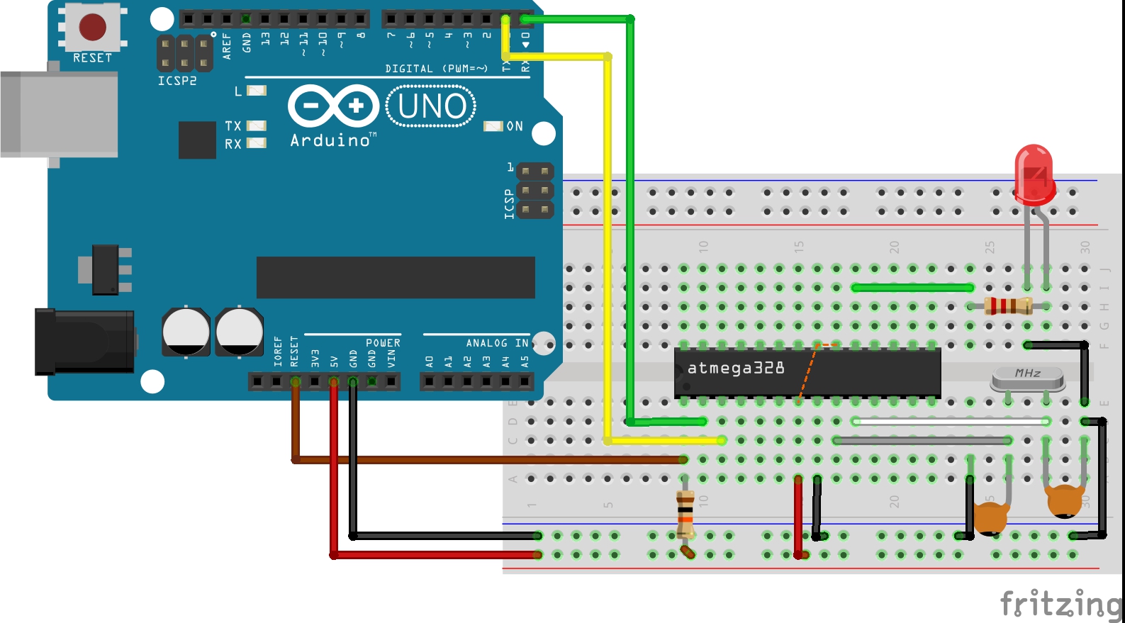
While using this approach, it is important to remove the microcontroller of the Arduino board to prevent interference.
Upload Code
Code upload process is the same as already described. Type the code to be uploaded or select an example -> select the board type (Duemilanove or Nano W/atmeg328), select the correct port and click upload. The code will be uploaded to the microcontroller.
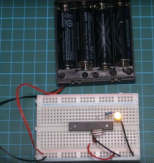
After successful code upload using any of the approaches described above, the Arduino or USB – Serial/TTL converter can be disconnected and the project connected to a battery to run on standalone as shown in the image below.
That’s it for this tutorial guys, thanks for following.
Feel free to drop questions and comments under the comment section, I will do my best to respond to them asap.
Till next time!


thanks,your tutorial was much helpful to me
0.1uf capacitor is ceramic or electrolytic?
0.1uF is 100nF and it’s a ceramic one.
can we connect this circuit without cristal osc.?
no,
Is a RST pin on the USB-TTL required?
Thanks you for detail tutor this is very help me
Thank you for your teaching it really help a lot. I have one challenge with the method of “By replacing the microcontroller on the Arduino UNO with the one to be programmed”. When I replaced the microcontroller on the Arduino board with the ATmega382P that was newly loaded with Bootloader, it gives me an error of “avrdude: stk500_recv (): programmer is not responding”. What could be the problem.
Hi, what do you mean by “removing the microcontroller of the Arduino board“?
Just remove the chip off the board and use the bare board as a programmer.