

PWM Module with Dual Source/Sink Outputs using SG3525
- Rajkumar Sharma
- 6.693 Views
- easy
- Tested
- SKU: EL101444
- Quote Now
- 0 Likes

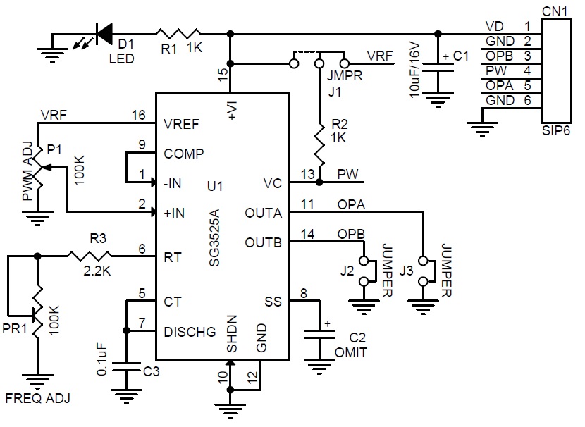
SG3525 PWM module is a great tool for every hobbyist. This circuit can be used in various applications such as switching power supply, DC-DC converter, DC motor speed controller, LED dimer, High voltage power supply, solenoid driver, and electronic DC load. This low-cost pulse width modulator control circuit offers improved performance. The circuit has various options such as adjustable PWM, adjustable frequency, optional soft start, dual source/sink output with 50% duty cycle, single output with 0 to 100% duty cycle and output signal voltage level TTL-5V or 12V selection using a jumper. The 5V PWM signal is rated at low current hence don’t draw more than 20mA. The 12V outputs are capable to drive a MOSFET directly.
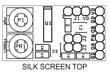
This module also has the feature of dual source/sink outputs. The output stages are totem-pole design capable of sinking and sourcing in excess of 200mA. The output stage of the SG3525A features NOR logic resulting in a low output for an off−state, both outputs are capable to drive the gate of a MOSFET. Open the jumpers J2 and J3 to set the module for source/sink mode. In this mode output frequency is 105Hz to 3.2Khz. Use R2 10 Ohms for source and sink mode.
Features
- Supply 12V DC (8-12V)
- Frequency 215Hz to 6.5Khz (Single Output Mode)
- Duty Cycle 0 to 100%
- Frequency 105 Hz to 3.2Khz Dual output Source/Sink
- Duty Cycle Dual mode 0 to 50%
- Soft start Optional (Mount C2 10/16V Capacitor for Soft start)
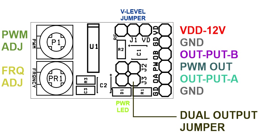
- On Board Power LED
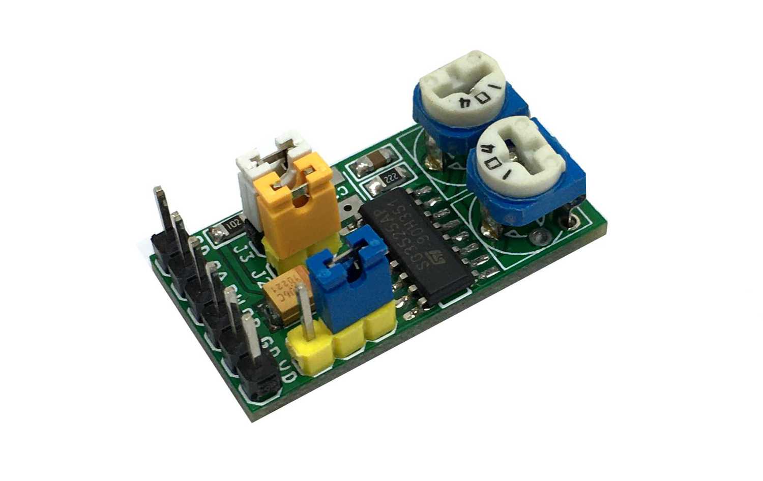
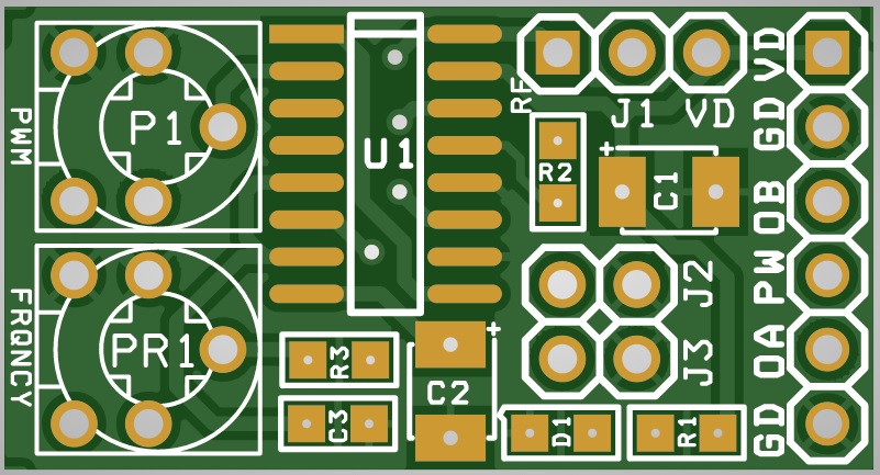
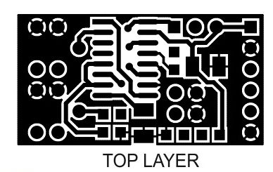
- PCB Dimensions 29.85X 15.88 mm
Single Output (0 to 100% Duty Cycle)
- Close Jumper J2 and J3
- Trimmer Potentiometer P1 Duty Cycle Adjust 0 to 100%
- Trimmer Potentiometer PR1 Frequency Adjust 215Hz to 6.5Khz
- Jumper J1 output voltage level selection 5V or 12V
- If soft start required: Mount C2 10uF/16V for soft start or Omit for normal operation
- CN1 Pin 4-PW and GND provides output
Dual Outputs ( 0 to 50% Duty Cycle)
- Open Jumper J2 and J3
- Trimmer Potentiometer P1 Duty Cycle Adjust 0 to 50%
- Trimmer Potentiometer PR1 Frequency Adjust 105Hz to 3.2Khz
- Jumper J1 output voltage level selection 5V or 12V
- If soft start required: Mount C2 10uF/16V for soft start or Omit for normal operation
- CN1 Pin 3 OPB and Pin 5 OPA dual source Sink outputs
Schematic
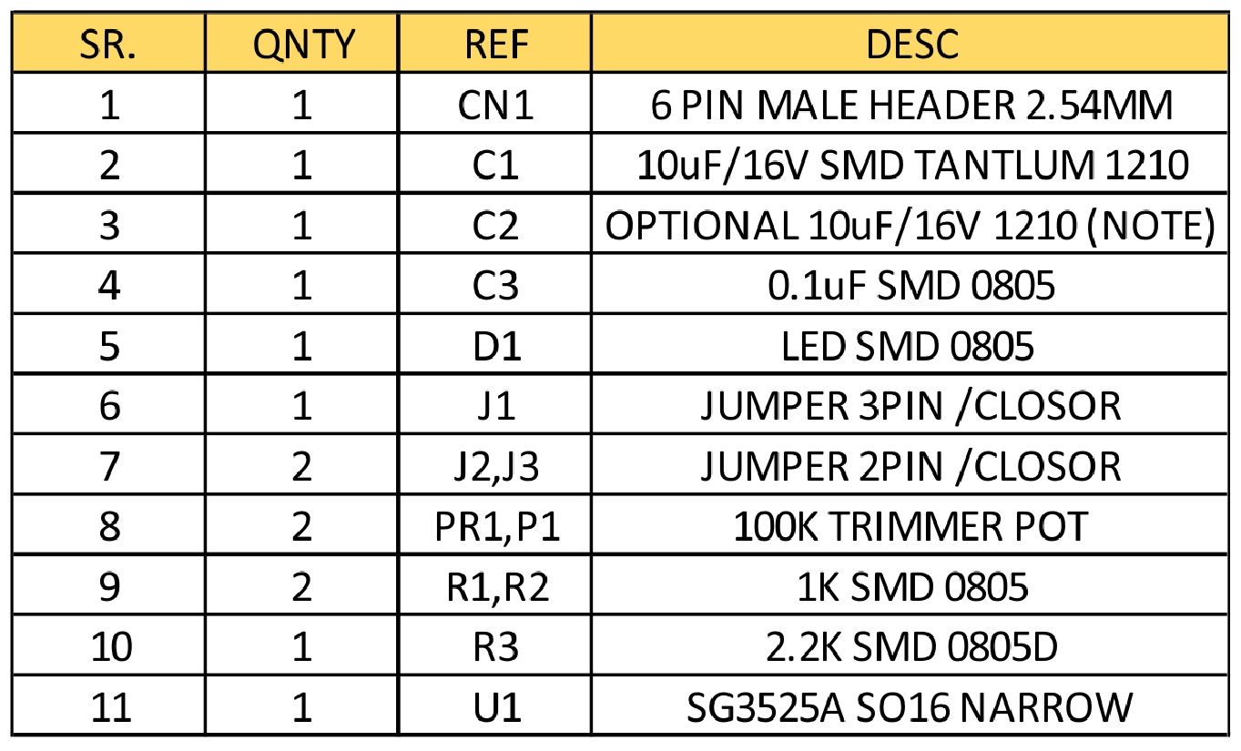
Parts List
Connections
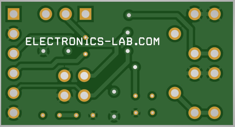
Gerber View
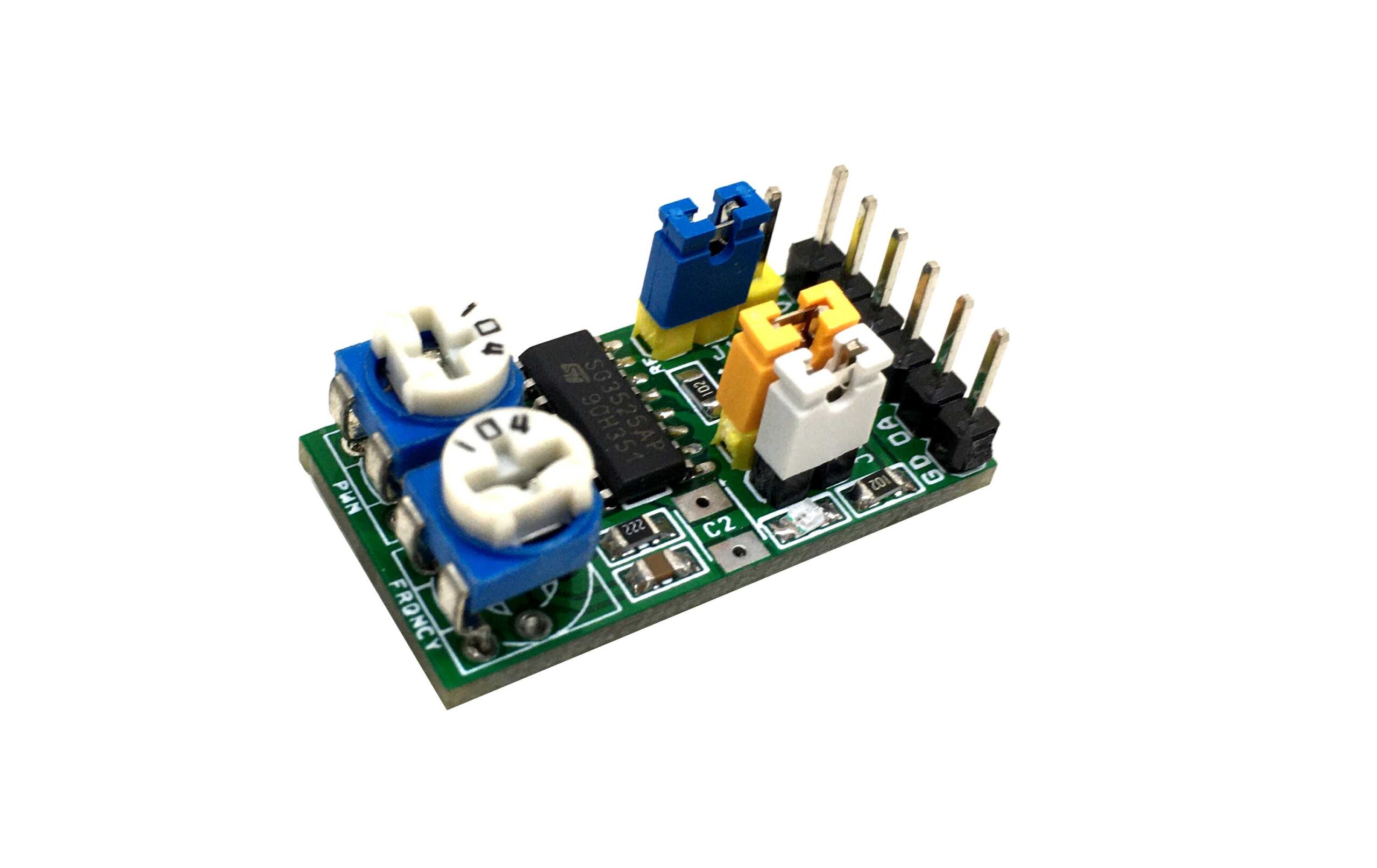
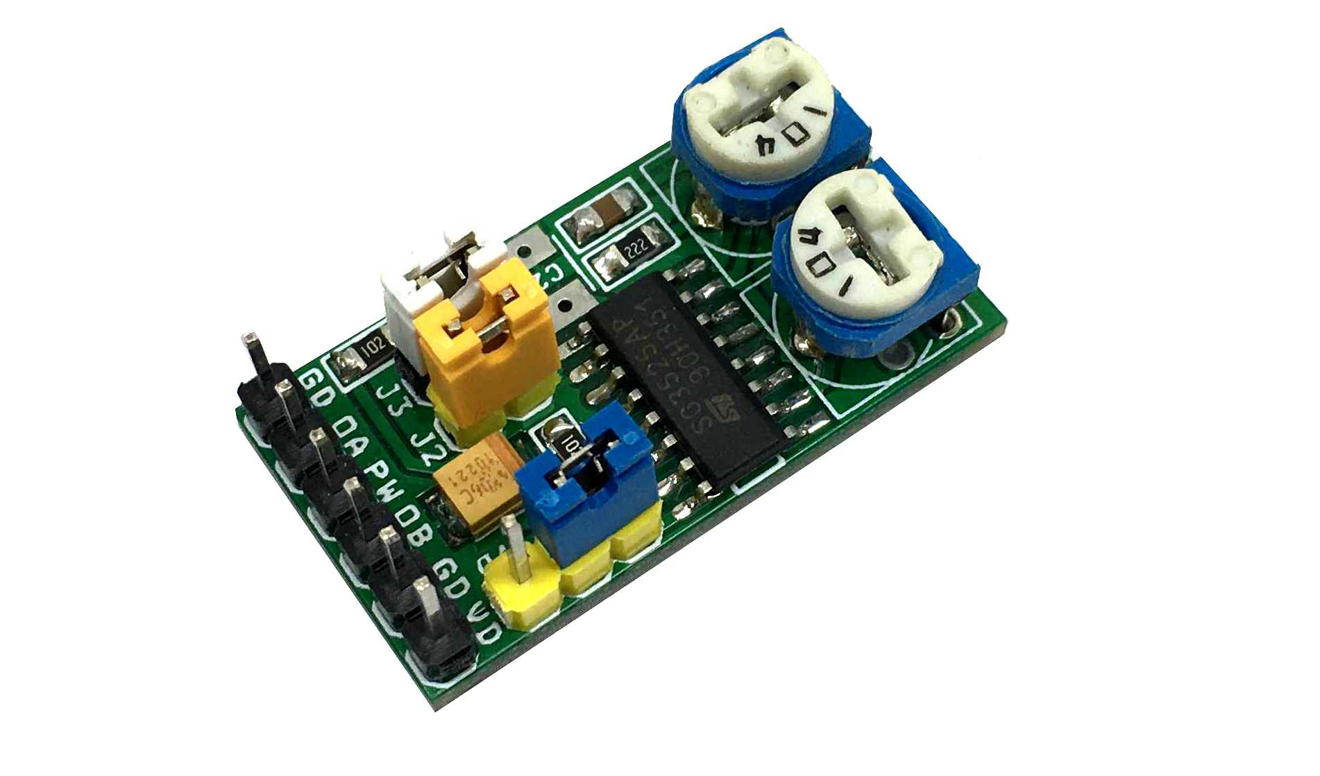
Photos
Video
SG3525 Datasheet
PCB


 – PWM Signal Generator")

