

Tiny Reflow Controller with OLED display
- Emmanuel Odunlade
- https://twitter.com/emmaodunlade
- emmaodunlade@gmail.com
- 11.073 Views
- medium
- Tested
- 1 Likes

Last time we examined how to build a DIY Reflow Oven controller using the Tiny Reflow Oven Controller v1 by Rocket Stream. However, Rocket Stream recently released the Tiny Reflow Controller V2 and for today’s tutorial, we will attempt to build this second version.
The Tiny Reflow controller v1 we discussed in the first article uses a LCD display and mostly SMD components and this kind of controller is required to control the heat process in reflow ovens to ensure the right amount of heat is supplied at all stages of the reflow process.
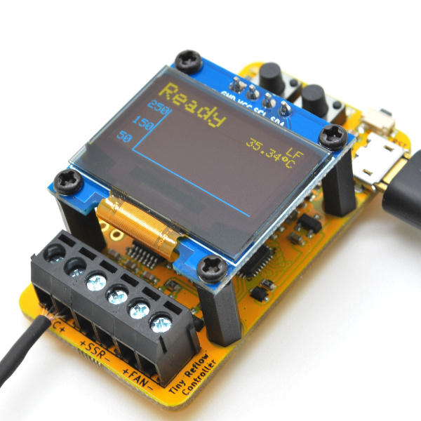
The Tiny Reflow controller v2 unlike the v1, is based on the Atmega328p Microcontroller. It retains the MAX31856 thermocouple interface used in the v1 but comes with a USB-Serial interface chip to facilitate programming and an OLED LCD instead of the 20×4 LCD display used on the v1. The OLED display ensures more information like the plot of the reflow curve can be provided as feedback to the users to give us a better understanding of the reflow process and state.
Like the v1, the Tiny Reflow controller v2 also features mostly SMD parts to keep the cost low (manual soldering and left over residue cleaning is time consuming) with the only through hole component being the terminal block (which doesn’t come in SMD type). This helped reduce the form factor/size of the reflow controller to the smallest possible and makes it a controller of choice in space constrained applications. To make the controller easy to power and simplify the design, all components used were streamlined to run on 3.3V voltage level.
The reflow controller v2 encompasses all you will need to control the reflow heat and you only need to connect a K type thermocouple (we recommend those with fiber glass or steel jacket), a Solid State Relay (SSR) (rated according to your oven), and the oven of course, connected to the terminal blocks of the controller.
Some of the highlighted features of the reflow Controller V2 include:
- Powered by ATmega328p
- MAX31856 thermocouple interface
- 0.96″ 128×64 OLED LCD yellow and blue color
- 1 terminal block for driving SSR (through an NPN transistor, 5mA @ 5V output) to control heating element/oven
- 1 terminal block for driving SSR (through an NPN transistor, 5mA @ 5V output) to control fan
- Warning Sounds via Buzzers
- ISP pins breakout to facilitate reprogramming
- Built-in USB-serial interface for firmware upload and serial interface
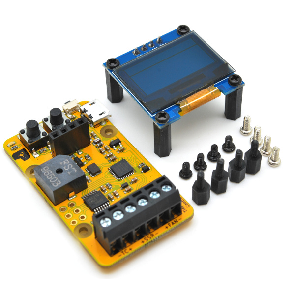
- Power via a MicroUSB connector with 500mA fuse
- Comes with extra 4 pieces of M2*5mm spacer (male-female) and 4 pieces of M2*5mm screws if you decided to mount it on the oven’s front panel
- FR4 TG140 PCB with immersion gold (ENIG) finish
- RoHS compliant
Required Components
The major components required to build this project include:
- ATmega328p microcontroller
- MAX31856 thermocouple interface IC
- K-Type Thermocouple (Rocket stream recommends those with fiberglass or steel jacket)
- 0.96″ OLED Display
- 2 push button
- LED
- 3 (dual port) Terminal Blocks
- 1 Buzzer
- An Oven
- External Solid State Relay
- A small fan
To prevent the list from becoming messy, other components required are provided in the table below. The Oven, External Solid State Relay and Fan are the only parts needed to test after building.
| Reference | Value |
| D1 | Red |
| U3 | MAX31856 |
| SW2 | IT-1109S |
| SW1 | IT-1109S |
| SW3 | TS-018 |
| R1 | 2K2 |
| LS1 | HYG9605B |
| R2 | 100R |
| R3 | 100R |
| C3 | 100nF |
| C2 | 10nF |
| C1 | 10nF |
| J4 | 2.54mm 2×3 |
| C4 | 100nF |
| C5 | 10uF 16V X5R |
| R4 | 10K |
| R5 | 10K |
| Q2 | 2N3904 |
| Q1 | 2N3904 |
| R6 | 2K2 |
| R7 | 27K |
| LOGO1 | LOGO-ROCKET-SCREAM |
| R8 | 53K6 |
| R9 | 10K |
| D3 | 1N4148WS |
| C6 | 100nF |
| C7 | 100nF |
| J2 | TERMINAL-BLOCK-1×2 |
| J1 | TERMINAL-BLOCK-1×2 |
| C8 | 100nF |
| C9 | 100nF |
| R10 | 10K |
| C11 | 100nF |
| C10 | 10uF 16V X5R |
| LOGO3 | LOGO-ROCKET-SCREAM |
| LOGO4 | LOGO-OSHW |
| LOGO2 | LOGO-KICAD |
| J3 | MICRO-USB |
| L1 | BLM18KG221SN1D |
| C12 | 10uF 16V X5R |
| F1 | FUSE |
| R11 | 2K2 |
| U4 | CH340E |
| C14 | 100nF |
| C13 | 100nF |
| U1 | ATMEGA328P-MU |
| C17 | 100nF |
| C18 | 100nF |
| L2 | LBMF1608T100K |
| Y1 | NX3225GD |
| C15 | 10pF |
| C16 | 10pF |
| U5 | OLED-SSD1306-128X64-I2C |
| C19 | 100nF |
| Q3 | 2N3904 |
| R12 | 53K6 |
| J5 | TERMINAL-BLOCK-1×2 |
| U2 | MCP1700T-3302E-TT |
Schematics
As mentioned during the introduction, the Tiny Reflow Controller v2 used SMD parts, which automatically means we need a PCB for our build. The major reason for this is to make the project neat, portable and cheap. However, you can also decide to get the through-hole version of this components and use them to implement the project on a breadboard.
To make it easy to implement the schematics and transition to PCB, the schematics for this project was developed using Kicad. The components are connected as shown in the schematics below;
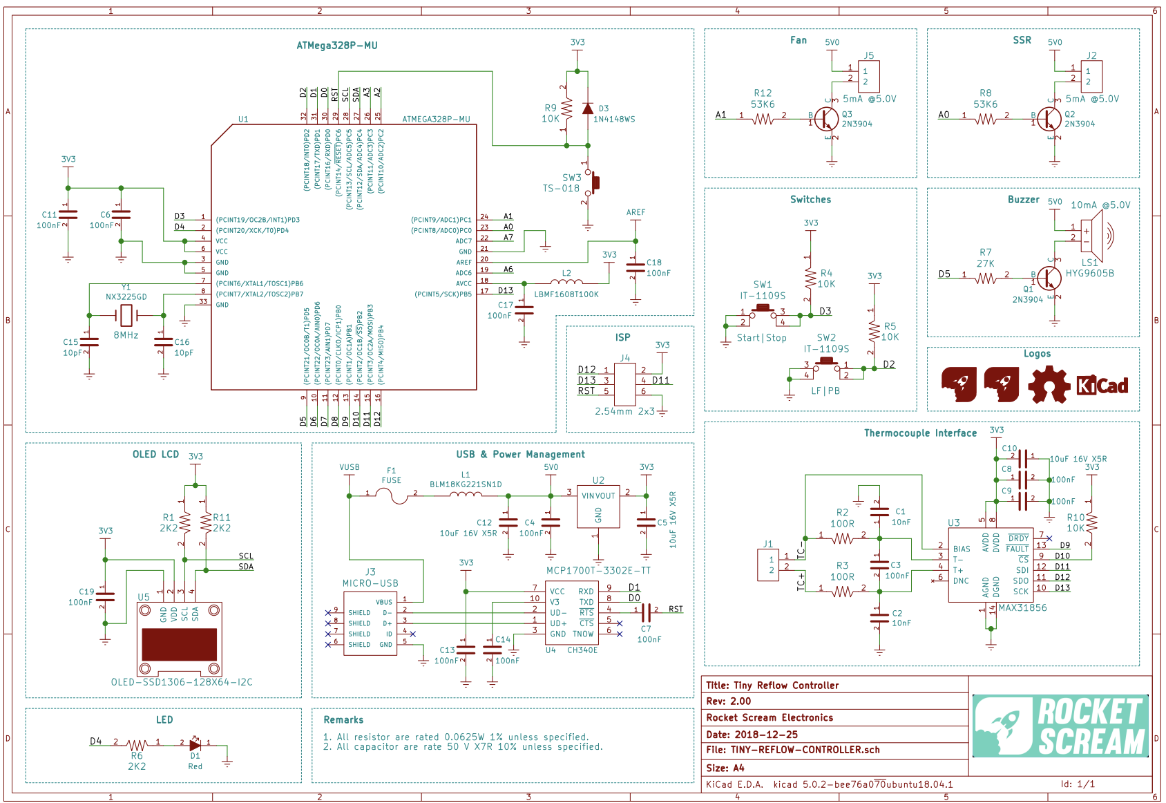
The final PCB design will look like the render below.
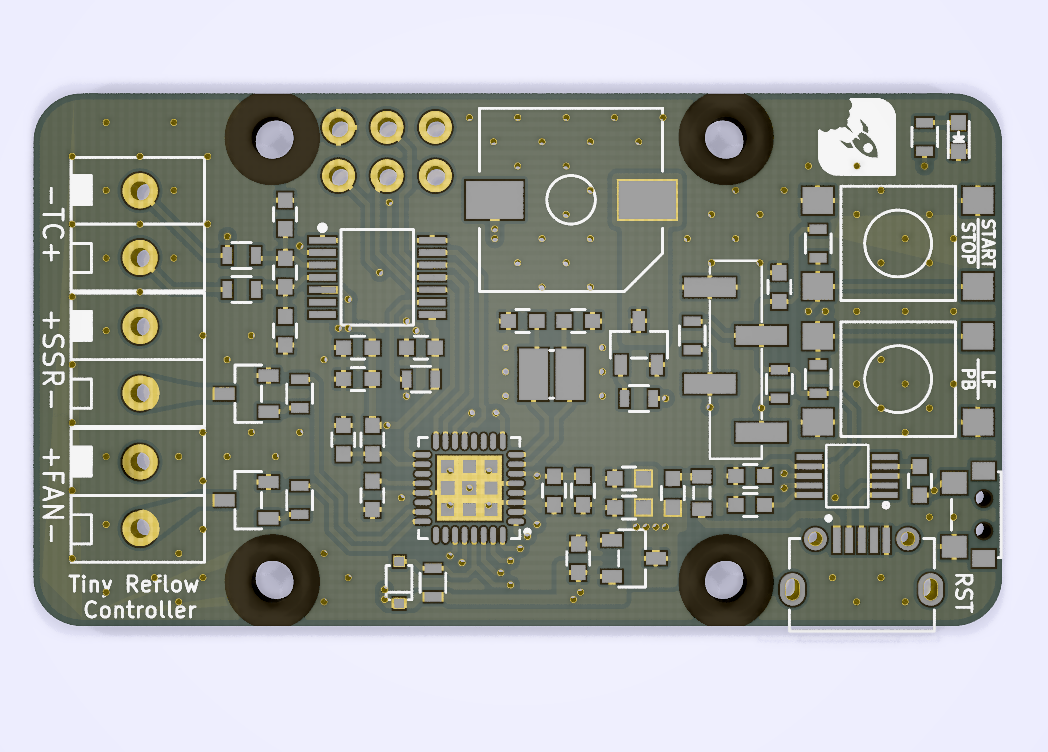
To make the board easy to replicate, all the design files including schematics and PCB are attached under the download section. Feel free to use within the license specifications.
Code
The code for this project will be developed using the Arduino ID and is based on the example code that is shipped with the Tiny Reflow Oven V2 by Rocket Stream. The sketch utilizes a PID based control algorithm of the awesome Arduino PID Library developed by Brett Beauregard and it is used to manage the reflow process, using the heater and the fan to ensure the heat is adequate for every stage of the reflow process.
The sketch utilizes three major libraries including; the Arduino PID Library already mentioned, Adafruit MAX31856 Library, Adafruit SSD1306 Library, and the Adafruit GFX Library. The PID library as mentioned earlier was used to ensure accuracy in heat levels with heat applied based on the current heat levels. The Adafruit SSD1306 and GFX libraries, on the other hand, were used to facilitate interaction with the OLED, and the Adafruit Max318356 library was used to reduce the amount of work involved in obtaining readings from the thermocouple sensor.
As usual, I will do a brief explanation of the code highlighting the major parts. The example code we will work with, takes into account both leaded and lead-free reflow oven configurations, allowing users to change from one to the other via a single push button.
We start the sketch by including all the libraries that we will use. In addition to the libraries already mentioned above, we will also use the Arduino EEPROM library, the Wire library and the SPI library. All these libraries come with the Arduino IDE so there is no need to manually install them.
// ***** INCLUDES *****
#include <SPI.h>
#include <Wire.h>
#include <EEPROM.h>
#include <LiquidCrystal.h>
#include <Adafruit_GFX.h>      // Comment for VERSION 1
#include <Adafruit_SSD1306.h>  // Comment for VERSION 1
#include <Adafruit_MAX31856.h>
#include <PID_v1.h>
Next, we create a type definition that holds several parameters to indicate the state of the reflow process.
// ***** TYPE DEFINITIONS *****
typedef enum REFLOW_STATE
{
  REFLOW_STATE_IDLE,
  REFLOW_STATE_PREHEAT,
  REFLOW_STATE_SOAK,
  REFLOW_STATE_REFLOW,
  REFLOW_STATE_COOL,
  REFLOW_STATE_COMPLETE,
  REFLOW_STATE_TOO_HOT,
  REFLOW_STATE_ERROR
} reflowState_t;
We also create other type declarations to hold the reflow status, switch status, debounce state and the Reflow_Profile based on the switch status.
ypedef enum REFLOW_STATUS
{
  REFLOW_STATUS_OFF,
  REFLOW_STATUS_ON
} reflowStatus_t;

typedef	enum SWITCH
{
  SWITCH_NONE,
  SWITCH_1,
  SWITCH_2
} switch_t;

typedef enum DEBOUNCE_STATE
{
  DEBOUNCE_STATE_IDLE,
  DEBOUNCE_STATE_CHECK,
  DEBOUNCE_STATE_RELEASE
} debounceState_t;

typedef enum REFLOW_PROFILE
{
  REFLOW_PROFILE_LEADFREE,
  REFLOW_PROFILE_LEADED
} reflowProfile_t;
Next, we create variables to hold constant values that will be used irrespective of the profile selected (General Profile constants) and we follow it up by creating variables to hold values specific to Lead-free profile and also create those specific to the Leaded profile. This ensures that irrespective of the profile selected by the user, the necessary information will be available.
// ***** CONSTANTS *****
// ***** GENERAL *****
#define VERSION 2 // Replace with 1 or 2

// ***** GENERAL PROFILE CONSTANTS *****
#define PROFILE_TYPE_ADDRESS 0
#define TEMPERATURE_ROOM 50
#define TEMPERATURE_SOAK_MIN 150
#define TEMPERATURE_COOL_MIN 100
#define SENSOR_SAMPLING_TIME 1000
#define SOAK_TEMPERATURE_STEP 5

// ***** LEAD FREE PROFILE CONSTANTS *****
#define TEMPERATURE_SOAK_MAX_LF 200
#define TEMPERATURE_REFLOW_MAX_LF 250
#define SOAK_MICRO_PERIOD_LF 9000

// ***** LEADED PROFILE CONSTANTS *****
#define TEMPERATURE_SOAK_MAX_PB 180
#define TEMPERATURE_REFLOW_MAX_PB 224
#define SOAK_MICRO_PERIOD_PB 10000

// ***** SWITCH SPECIFIC CONSTANTS *****
#define DEBOUNCE_PERIOD_MIN 100
Next, we create variables to be used by the PID Algorithm, specify the project version so the right display is used, and create messages to be displayed on the OLED along with a few other variables. The names are very descriptive so it should be easy to follow.
/ ***** PID PARAMETERS *****
// ***** PRE-HEAT STAGE *****
#define PID_KP_PREHEAT 100
#define PID_KI_PREHEAT 0.025
#define PID_KD_PREHEAT 20
// ***** SOAKING STAGE *****
#define PID_KP_SOAK 300
#define PID_KI_SOAK 0.05
#define PID_KD_SOAK 250
// ***** REFLOW STAGE *****
#define PID_KP_REFLOW 300
#define PID_KI_REFLOW 0.05
#define PID_KD_REFLOW 350
#define PID_SAMPLE_TIME 1000

#if VERSION == 2
#define SCREEN_WIDTH 128 // OLED display width, in pixels
#define SCREEN_HEIGHT 64 // OLED display height, in pixels
#define X_AXIS_START 18 // X-axis starting position
#endif

// ***** LCD MESSAGES *****
const char* lcdMessagesReflowStatus[] = {
  "Ready",
  "Pre",
  "Soak",
  "Reflow",
  "Cool",
  "Done!",
  "Hot!",
  "Error"
};
The sketch was designed to be compatible with the v1 of the project, with the version decision being made by the version indicated by the user in the code. As a result, you may continue to see things that relate to the first version of the project. Next, we declare the pins to which the displays are connected, with the OLED declarations under v2.
// ***** PIN ASSIGNMENT *****
#if VERSION == 1
unsigned char ssrPin = 3;
unsigned char thermocoupleCSPin = 2;
unsigned char lcdRsPin = 10;
unsigned char lcdEPin = 9;
unsigned char lcdD4Pin = 8;
unsigned char lcdD5Pin = 7;
unsigned char lcdD6Pin = 6;
unsigned char lcdD7Pin = 5;
unsigned char buzzerPin = 14;
unsigned char switchPin = A1;
unsigned char ledPin = LED_BUILTIN;
#elif VERSION == 2
unsigned char ssrPin = A0;
unsigned char fanPin = A1;
unsigned char thermocoupleCSPin = 10;
unsigned char ledPin = 4;
unsigned char buzzerPin = 5;
unsigned char switchStartStopPin = 3;
unsigned char switchLfPbPin = 2;
#endif
Several other important variables are also declared with self descriptive names.
// ***** PID CONTROL VARIABLES *****
double setpoint;
double input;
double output;
double kp = PID_KP_PREHEAT;
double ki = PID_KI_PREHEAT;
double kd = PID_KD_PREHEAT;
int windowSize;
unsigned long windowStartTime;
unsigned long nextCheck;
unsigned long nextRead;
unsigned long updateLcd;
unsigned long timerSoak;
unsigned long buzzerPeriod;
unsigned char soakTemperatureMax;
unsigned char reflowTemperatureMax;
unsigned long soakMicroPeriod;
// Reflow oven controller state machine state variable
reflowState_t reflowState;
// Reflow oven controller status
reflowStatus_t reflowStatus;
// Reflow profile type
reflowProfile_t reflowProfile;
// Switch debounce state machine state variable
debounceState_t debounceState;
// Switch debounce timer
long lastDebounceTime;
// Switch press status
switch_t switchStatus;
switch_t switchValue;
switch_t switchMask;
// Seconds timer
unsigned int timerSeconds;
// Thermocouple fault status
unsigned char fault;
With all the variables created, we then create an instance of the PID, the SSD1306 and the MAX31856 libraries after which we move to the void setup() function.
/ PID control interface
PID reflowOvenPID(&input, &output, &setpoint, kp, ki, kd, DIRECT);
#if VERSION == 1
// LCD interface
LiquidCrystal lcd(lcdRsPin, lcdEPin, lcdD4Pin, lcdD5Pin, lcdD6Pin, lcdD7Pin);
#elif VERSION == 2
Adafruit_SSD1306 oled(SCREEN_WIDTH, SCREEN_HEIGHT, &Wire);
#endif
// MAX31856 thermocouple interface
Adafruit_MAX31856 thermocouple = Adafruit_MAX31856(thermocoupleCSPin);
We start the void setup() function by checking the currently selected reflow profile on the EEPROM and this helps determine which of the variable groups should be selected. If no reflow profile was previously stored, the system selects the Lead-free profile by default.
void setup()
{
  // Check current selected reflow profile
  unsigned char value = EEPROM.read(PROFILE_TYPE_ADDRESS);
  if ((value == 0) || (value == 1))
  {
    // Valid reflow profile value
    reflowProfile = value;
  }
  else
  {
    // Default to lead-free profile
    EEPROM.write(PROFILE_TYPE_ADDRESS, 0);
    reflowProfile = REFLOW_PROFILE_LEADFREE;
  }
Next, we initialize the SSR pin to ensure the reflow oven is open after which we initialize the buzzer setting it to turn on immediately when the system powers up, the status LED is also powered on when the systems starts.
// SSR pin initialization to ensure reflow oven is off
digitalWrite(ssrPin, LOW);
pinMode(ssrPin, OUTPUT);

// Buzzer pin initialization to ensure annoying buzzer is off
digitalWrite(buzzerPin, LOW);
pinMode(buzzerPin, OUTPUT);

// LED pins initialization and turn on upon start-up (active high)
pinMode(ledPin, OUTPUT);
digitalWrite(ledPin, HIGH);
Next, we initialize the thermocouple, indicating the type, and also initialize the OLED and display a sort of splash screen with the date and version of the controller. The code selectively runs every thing marked for 2.
  // Initialize thermocouple interface
  thermocouple.begin();
  thermocouple.setThermocoupleType(MAX31856_TCTYPE_K);

  // Start-up splash
  digitalWrite(buzzerPin, HIGH);
#if VERSION == 1
  lcd.begin(8, 2);
  lcd.createChar(0, degree);
  lcd.clear();
  lcd.print(F(" Tiny  "));
  lcd.setCursor(0, 1);
  lcd.print(F(" Reflow "));
#elif VERSION == 2
  oled.begin(SSD1306_SWITCHCAPVCC, 0x3C);
  oled.display();
#endif
  digitalWrite(buzzerPin, LOW);
  delay(2000);
#if VERSION == 1
  lcd.clear();
  lcd.print(F(" v1.00  "));
  lcd.setCursor(0, 1);
  lcd.print(F("26-07-17"));
  delay(2000);
  lcd.clear();
#elif VERSION == 2
  oled.clearDisplay();
  oled.setTextSize(1);
  oled.setTextColor(WHITE);
  oled.setCursor(0, 0);
  oled.println(F("     Tiny Reflow"));
  oled.println(F("     Controller"));
  oled.println();
  oled.println(F("       v2.00"));
  oled.println();
  oled.println(F("      04-03-19"));
  oled.display();
  delay(3000);
  oled.clearDisplay();
#endif
Next, we initialize serial communication, turn off the Status LED, and initialize the variables we will use to monitor time as the sketch runs.
// Serial communication at 115200 bps
  Serial.begin(115200);

  // Turn off LED (active high)
  digitalWrite(ledPin, LOW);
  // Set window size
  windowSize = 2000;
  // Initialize time keeping variable
  nextCheck = millis();
  // Initialize thermocouple reading variable
  nextRead = millis();
  // Initialize LCD update timer
  updateLcd = millis();
}
With this done, we move to the void loop() function where all the major actions take place.
The code for the void loop() function is quite bulky but the idea is simple. We use the variables created earlier to manage the reflow process, monitoring the amount of heat with the thermocouple, and using that information as an input into the PID algorithm which then determines how the heater operates. For each stage in the reflow process, the PID operates in such a way that the designated amount of heat for that stage is achieved. While all of this is going on, the time and temperature information are also being displayed on the screen to provide visual feedback to the user and the switches which are used to set the reflow status and the reflow profile are also being watched so the system can act immediately on any change in their state.
void loop()
{
  // Current time
  unsigned long now;

  // Time to read thermocouple?
  if (millis() > nextRead)
  {
    // Read thermocouple next sampling period
    nextRead += SENSOR_SAMPLING_TIME;
    // Read current temperature
    input = thermocouple.readThermocoupleTemperature();
    // Check for thermocouple fault
    fault = thermocouple.readFault();

    // If any thermocouple fault is detected
    if ((fault & MAX31856_FAULT_CJRANGE) ||
        (fault & MAX31856_FAULT_TCRANGE) ||
        (fault & MAX31856_FAULT_CJHIGH) ||
        (fault & MAX31856_FAULT_CJLOW) ||
        (fault & MAX31856_FAULT_TCHIGH) ||
        (fault & MAX31856_FAULT_TCLOW) ||
        (fault & MAX31856_FAULT_OVUV) ||
        (fault & MAX31856_FAULT_OPEN))
    {
      // Illegal operation
      reflowState = REFLOW_STATE_ERROR;
      reflowStatus = REFLOW_STATUS_OFF;
      Serial.println(F("Error"));
    }
  }

  if (millis() > nextCheck)
  {
    // Check input in the next seconds
    nextCheck += SENSOR_SAMPLING_TIME;
    // If reflow process is on going
    if (reflowStatus == REFLOW_STATUS_ON)
    {
      // Toggle red LED as system heart beat
      digitalWrite(ledPin, !(digitalRead(ledPin)));
      // Increase seconds timer for reflow curve plot
      timerSeconds++;
      // Send temperature and time stamp to serial
      Serial.print(timerSeconds);
      Serial.print(F(","));
      Serial.print(setpoint);
      Serial.print(F(","));
      Serial.print(input);
      Serial.print(F(","));
      Serial.println(output);
    }
    else
    {
      // Turn off red LED
      digitalWrite(ledPin, LOW);
    }
  }

  if (millis() > updateLcd)
  {
    // Update LCD in the next 100 ms
    updateLcd += UPDATE_RATE;
#if VERSION == 1
    // Clear LCD
    lcd.clear();
    // Print current system state
    lcd.print(lcdMessagesReflowStatus[reflowState]);
    lcd.setCursor(6, 0);
    if (reflowProfile == REFLOW_PROFILE_LEADFREE)
    {
      lcd.print(F("LF"));
    }
    else
    {
      lcd.print(F("PB"));
    }
    lcd.setCursor(0, 1);

    // If currently in error state
    if (reflowState == REFLOW_STATE_ERROR)
    {
      // Thermocouple error (open, shorted)
      lcd.print(F("TC Error"));
    }
    else
    {
      // Display current temperature
      lcd.print(input);
#if ARDUINO >= 100
      // Display degree Celsius symbol
      lcd.write((uint8_t)0);
#else
      // Display degree Celsius symbol
      lcd.print(0, BYTE);
#endif
      lcd.print("C ");
    }
#elif VERSION == 2
    oled.clearDisplay();
    oled.setTextSize(2);
    oled.setCursor(0, 0);
    oled.print(lcdMessagesReflowStatus[reflowState]);
    oled.setTextSize(1);
    oled.setCursor(115, 0);

    if (reflowProfile == REFLOW_PROFILE_LEADFREE)
    {
      oled.print(F("LF"));
    }
    else
    {
      oled.print(F("PB"));
    }

    // Temperature markers
    oled.setCursor(0, 18);
    oled.print(F("250"));
    oled.setCursor(0, 36);
    oled.print(F("150"));
    oled.setCursor(0, 54);
    oled.print(F("50"));
    // Draw temperature and time axis
    oled.drawLine(18, 18, 18, 63, WHITE);
    oled.drawLine(18, 63, 127, 63, WHITE);
    oled.setCursor(115, 0);

    // If currently in error state
    if (reflowState == REFLOW_STATE_ERROR)
    {
      oled.setCursor(80, 9);
      oled.print(F("TC Error"));
    }
    else
    {
      // Right align temperature reading
      if (input < 10) oled.setCursor(91, 9);
      else if (input < 100) oled.setCursor(85,9);
      else oled.setCursor(80, 9);
      // Display current temperature
      oled.print(input);
      oled.print((char)247);
      oled.print(F("C"));
    }

    if (reflowStatus == REFLOW_STATUS_ON)
    {
      // We are updating the display faster than sensor reading
      if (timerSeconds > timerUpdate)
      {
        // Store temperature reading every 3 s
        if ((timerSeconds % 3) == 0)
        {
          timerUpdate = timerSeconds;
          unsigned char averageReading = map(input, 0, 250, 63, 19);
          if (x < (SCREEN_WIDTH - X_AXIS_START))
          {
            temperature[x++] = averageReading;
          }
        }
      }
    }

    unsigned char timeAxis;
    for (timeAxis = 0; timeAxis < x; timeAxis++)
    {
      oled.drawPixel(timeAxis + X_AXIS_START, temperature[timeAxis], WHITE);
    }

    // Update screen
    oled.display();
#endif
  }

  // Reflow oven controller state machine
  switch (reflowState)
  {
    case REFLOW_STATE_IDLE:
      // If oven temperature is still above room temperature
      if (input >= TEMPERATURE_ROOM)
      {
        reflowState = REFLOW_STATE_TOO_HOT;
      }
      else
      {
        // If switch is pressed to start reflow process
        if (switchStatus == SWITCH_1)
        {
          // Send header for CSV file
          Serial.println(F("Time,Setpoint,Input,Output"));
          // Intialize seconds timer for serial debug information
          timerSeconds = 0;

          #if VERSION == 2
          // Initialize reflow plot update timer
          timerUpdate = 0;

          for (x = 0; x < (SCREEN_WIDTH - X_AXIS_START); x++)
          {
            temperature[x] = 0;
          }
          // Initialize index for average temperature array used for reflow plot
          x = 0;
          #endif

          // Initialize PID control window starting time
          windowStartTime = millis();
          // Ramp up to minimum soaking temperature
          setpoint = TEMPERATURE_SOAK_MIN;
          // Load profile specific constant
          if (reflowProfile == REFLOW_PROFILE_LEADFREE)
          {
            soakTemperatureMax = TEMPERATURE_SOAK_MAX_LF;
            reflowTemperatureMax = TEMPERATURE_REFLOW_MAX_LF;
            soakMicroPeriod = SOAK_MICRO_PERIOD_LF;
          }
          else
          {
            soakTemperatureMax = TEMPERATURE_SOAK_MAX_PB;
            reflowTemperatureMax = TEMPERATURE_REFLOW_MAX_PB;
            soakMicroPeriod = SOAK_MICRO_PERIOD_PB;
          }
          // Tell the PID to range between 0 and the full window size
          reflowOvenPID.SetOutputLimits(0, windowSize);
          reflowOvenPID.SetSampleTime(PID_SAMPLE_TIME);
          // Turn the PID on
          reflowOvenPID.SetMode(AUTOMATIC);
          // Proceed to preheat stage
          reflowState = REFLOW_STATE_PREHEAT;
        }
      }
      break;

    case REFLOW_STATE_PREHEAT:
      reflowStatus = REFLOW_STATUS_ON;
      // If minimum soak temperature is achieve
      if (input >= TEMPERATURE_SOAK_MIN)
      {
        // Chop soaking period into smaller sub-period
        timerSoak = millis() + soakMicroPeriod;
        // Set less agressive PID parameters for soaking ramp
        reflowOvenPID.SetTunings(PID_KP_SOAK, PID_KI_SOAK, PID_KD_SOAK);
        // Ramp up to first section of soaking temperature
        setpoint = TEMPERATURE_SOAK_MIN + SOAK_TEMPERATURE_STEP;
        // Proceed to soaking state
        reflowState = REFLOW_STATE_SOAK;
      }
      break;

    case REFLOW_STATE_SOAK:
      // If micro soak temperature is achieved
      if (millis() > timerSoak)
      {
        timerSoak = millis() + soakMicroPeriod;
        // Increment micro setpoint
        setpoint += SOAK_TEMPERATURE_STEP;
        if (setpoint > soakTemperatureMax)
        {
          // Set agressive PID parameters for reflow ramp
          reflowOvenPID.SetTunings(PID_KP_REFLOW, PID_KI_REFLOW, PID_KD_REFLOW);
          // Ramp up to first section of soaking temperature
          setpoint = reflowTemperatureMax;
          // Proceed to reflowing state
          reflowState = REFLOW_STATE_REFLOW;
        }
      }
      break;

    case REFLOW_STATE_REFLOW:
      // We need to avoid hovering at peak temperature for too long
      // Crude method that works like a charm and safe for the components
      if (input >= (reflowTemperatureMax - 5))
      {
        // Set PID parameters for cooling ramp
        reflowOvenPID.SetTunings(PID_KP_REFLOW, PID_KI_REFLOW, PID_KD_REFLOW);
        // Ramp down to minimum cooling temperature
        setpoint = TEMPERATURE_COOL_MIN;
        // Proceed to cooling state
        reflowState = REFLOW_STATE_COOL;
      }
      break;

    case REFLOW_STATE_COOL:
      // If minimum cool temperature is achieve
      if (input <= TEMPERATURE_COOL_MIN)
      {
        // Retrieve current time for buzzer usage
        buzzerPeriod = millis() + 1000;
        // Turn on buzzer to indicate completion
        digitalWrite(buzzerPin, HIGH);
        // Turn off reflow process
        reflowStatus = REFLOW_STATUS_OFF;
        // Proceed to reflow Completion state
        reflowState = REFLOW_STATE_COMPLETE;
      }
      break;

    case REFLOW_STATE_COMPLETE:
      if (millis() > buzzerPeriod)
      {
        // Turn off buzzer
        digitalWrite(buzzerPin, LOW);
        // Reflow process ended
        reflowState = REFLOW_STATE_IDLE;
      }
      break;

    case REFLOW_STATE_TOO_HOT:
      // If oven temperature drops below room temperature
      if (input < TEMPERATURE_ROOM)
      {
        // Ready to reflow
        reflowState = REFLOW_STATE_IDLE;
      }
      break;

    case REFLOW_STATE_ERROR:
      // Check for thermocouple fault
      fault = thermocouple.readFault();

      // If thermocouple problem is still present
      if ((fault & MAX31856_FAULT_CJRANGE) ||
          (fault & MAX31856_FAULT_TCRANGE) ||
          (fault & MAX31856_FAULT_CJHIGH) ||
          (fault & MAX31856_FAULT_CJLOW) ||
          (fault & MAX31856_FAULT_TCHIGH) ||
          (fault & MAX31856_FAULT_TCLOW) ||
          (fault & MAX31856_FAULT_OVUV) ||
          (fault & MAX31856_FAULT_OPEN))
      {
        // Wait until thermocouple wire is connected
        reflowState = REFLOW_STATE_ERROR;
      }
      else
      {
        // Clear to perform reflow process
        reflowState = REFLOW_STATE_IDLE;
      }
      break;
  }

  // If switch 1 is pressed
  if (switchStatus == SWITCH_1)
  {
    // If currently reflow process is on going
    if (reflowStatus == REFLOW_STATUS_ON)
    {
      // Button press is for cancelling
      // Turn off reflow process
      reflowStatus = REFLOW_STATUS_OFF;
      // Reinitialize state machine
      reflowState = REFLOW_STATE_IDLE;
    }
  }
  // Switch 2 is pressed
  else if (switchStatus == SWITCH_2)
  {
    // Only can switch reflow profile during idle
    if (reflowState == REFLOW_STATE_IDLE)
    {
      // Currently using lead-free reflow profile
      if (reflowProfile == REFLOW_PROFILE_LEADFREE)
      {
        // Switch to leaded reflow profile
        reflowProfile = REFLOW_PROFILE_LEADED;
        EEPROM.write(PROFILE_TYPE_ADDRESS, 1);
      }
      // Currently using leaded reflow profile
      else
      {
        // Switch to lead-free profile
        reflowProfile = REFLOW_PROFILE_LEADFREE;
        EEPROM.write(PROFILE_TYPE_ADDRESS, 0);
      }
    }
  }
  // Switch status has been read
  switchStatus = SWITCH_NONE;

  // Simple switch debounce state machine (analog switch)
  switch (debounceState)
  {
    case DEBOUNCE_STATE_IDLE:
      // No valid switch press
      switchStatus = SWITCH_NONE;

      switchValue = readSwitch();

      // If either switch is pressed
      if (switchValue != SWITCH_NONE)
      {
        // Keep track of the pressed switch
        switchMask = switchValue;
        // Intialize debounce counter
        lastDebounceTime = millis();
        // Proceed to check validity of button press
        debounceState = DEBOUNCE_STATE_CHECK;
      }
      break;

    case DEBOUNCE_STATE_CHECK:
      switchValue = readSwitch();
      if (switchValue == switchMask)
      {
        // If minimum debounce period is completed
        if ((millis() - lastDebounceTime) > DEBOUNCE_PERIOD_MIN)
        {
          // Valid switch press
          switchStatus = switchMask;
          // Proceed to wait for button release
          debounceState = DEBOUNCE_STATE_RELEASE;
        }
      }
      // False trigger
      else
      {
        // Reinitialize button debounce state machine
        debounceState = DEBOUNCE_STATE_IDLE;
      }
      break;

    case DEBOUNCE_STATE_RELEASE:
      switchValue = readSwitch();
      if (switchValue == SWITCH_NONE)
      {
        // Reinitialize button debounce state machine
        debounceState = DEBOUNCE_STATE_IDLE;
      }
      break;
  }

  // PID computation and SSR control
  if (reflowStatus == REFLOW_STATUS_ON)
  {
    now = millis();

    reflowOvenPID.Compute();

    if ((now - windowStartTime) > windowSize)
    {
      // Time to shift the Relay Window
      windowStartTime += windowSize;
    }
    if (output > (now - windowStartTime)) digitalWrite(ssrPin, HIGH);
    else digitalWrite(ssrPin, LOW);
  }
  // Reflow oven process is off, ensure oven is off
  else
  {
    digitalWrite(ssrPin, LOW);
  }
}
The complete Sketch for the project is quite bulky so it is attached to the zip file under the download section, at the end of the page.
Demo
One great thing about the Tiny Reflow Controller v2 is the fact that it comes with a USB port through which it can be programmed. However, you may still need to do some work on your Arduino IDE (like Flashing the bootloader to the Atmeg328p in case it doesn’t come with one) to ensure you can upload code to it. You can check out this tutorial we wrote a while back on the programming the Atmega328p with the Arduino IDE.
This board uses the stock Arduino Pro Mini ATmega328 3.3V 8MHz bootloader and it can be loaded just like V1 using the AVRISP mkII.
Connect the completed Reflow Controller v2 to your computer. Copy the code above, Paste in the IDE, Verify and hit the upload button. After uploading, you should see the splashscreen come up as shown in the image below, connect your SSR, fan and thermocouple. The Reflow controller is ready for use.
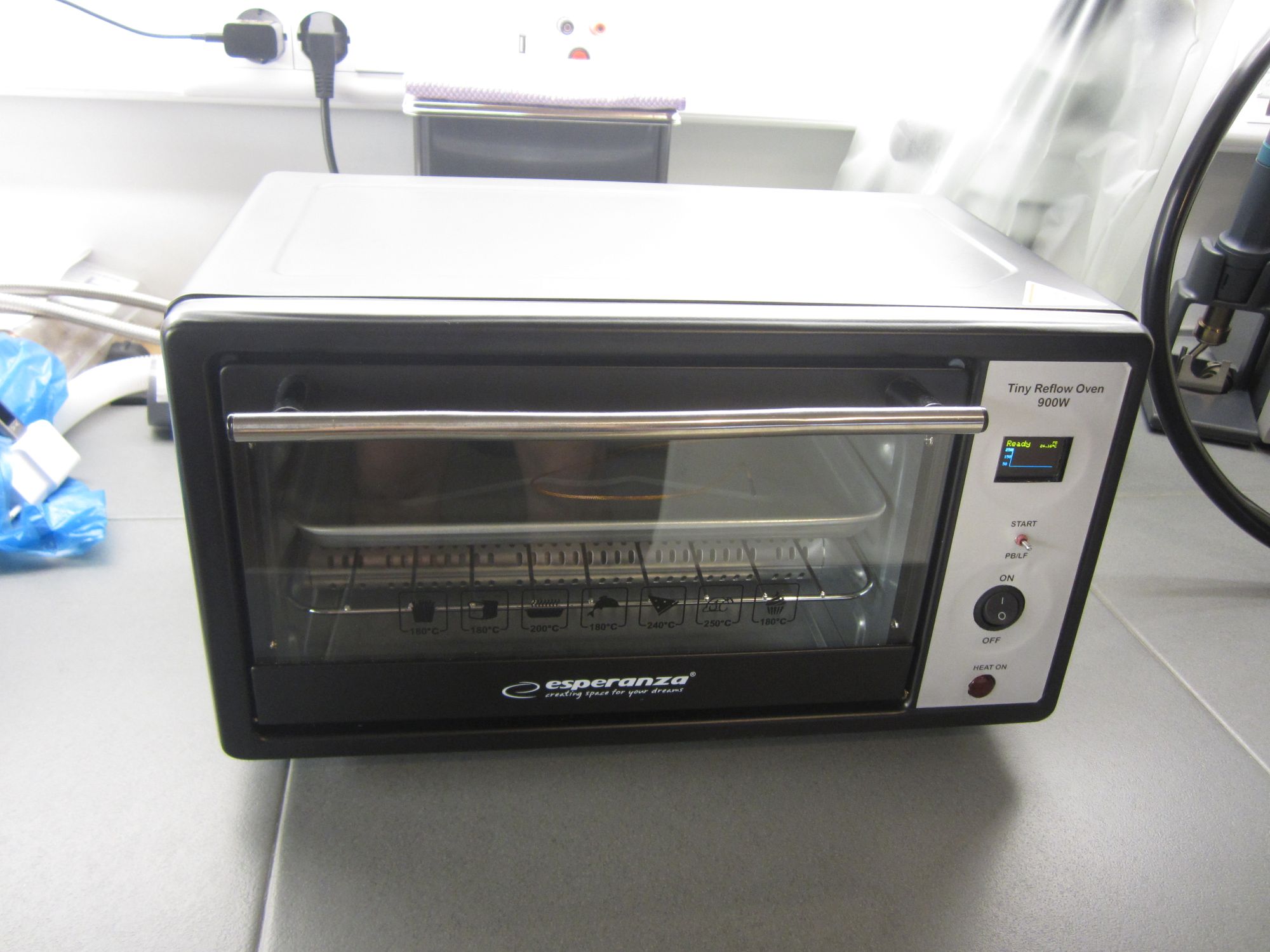
Installation
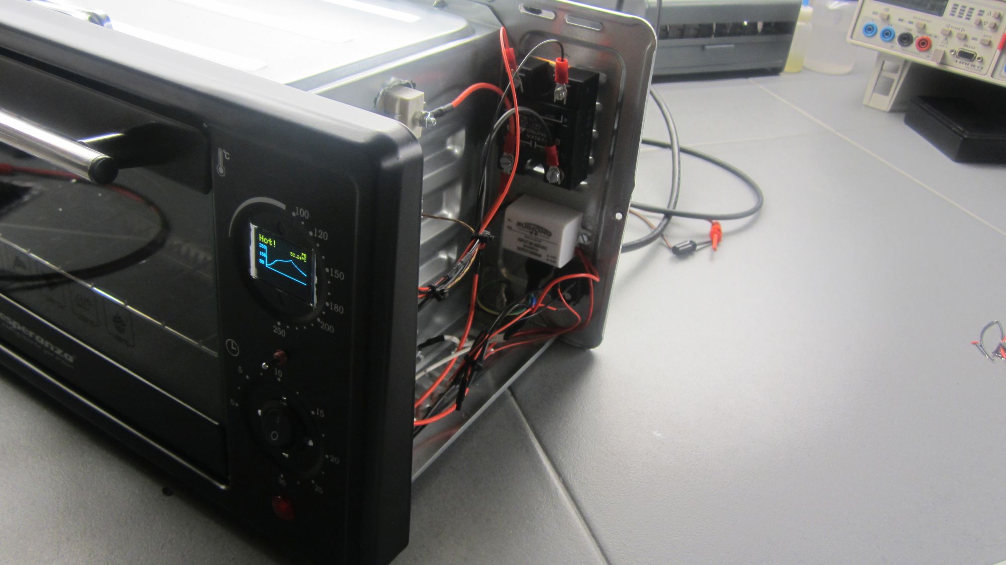
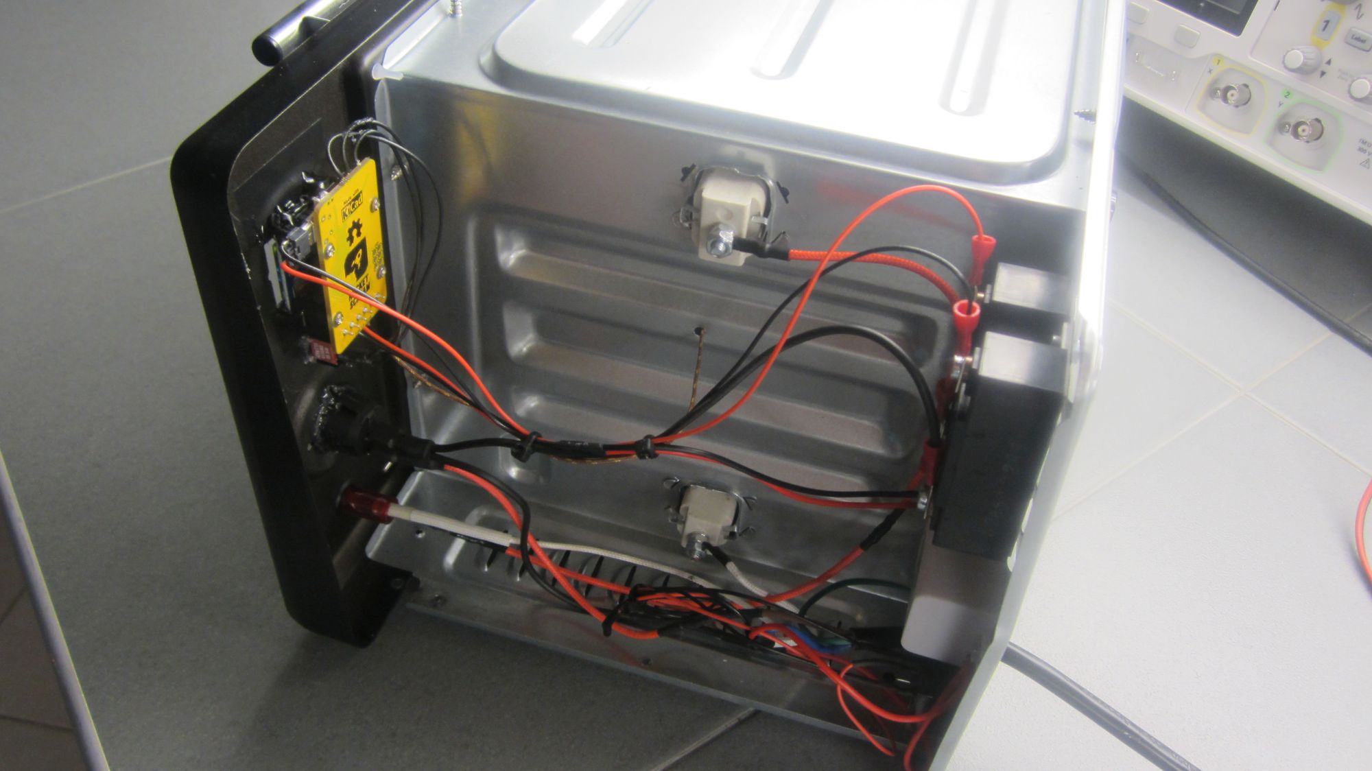
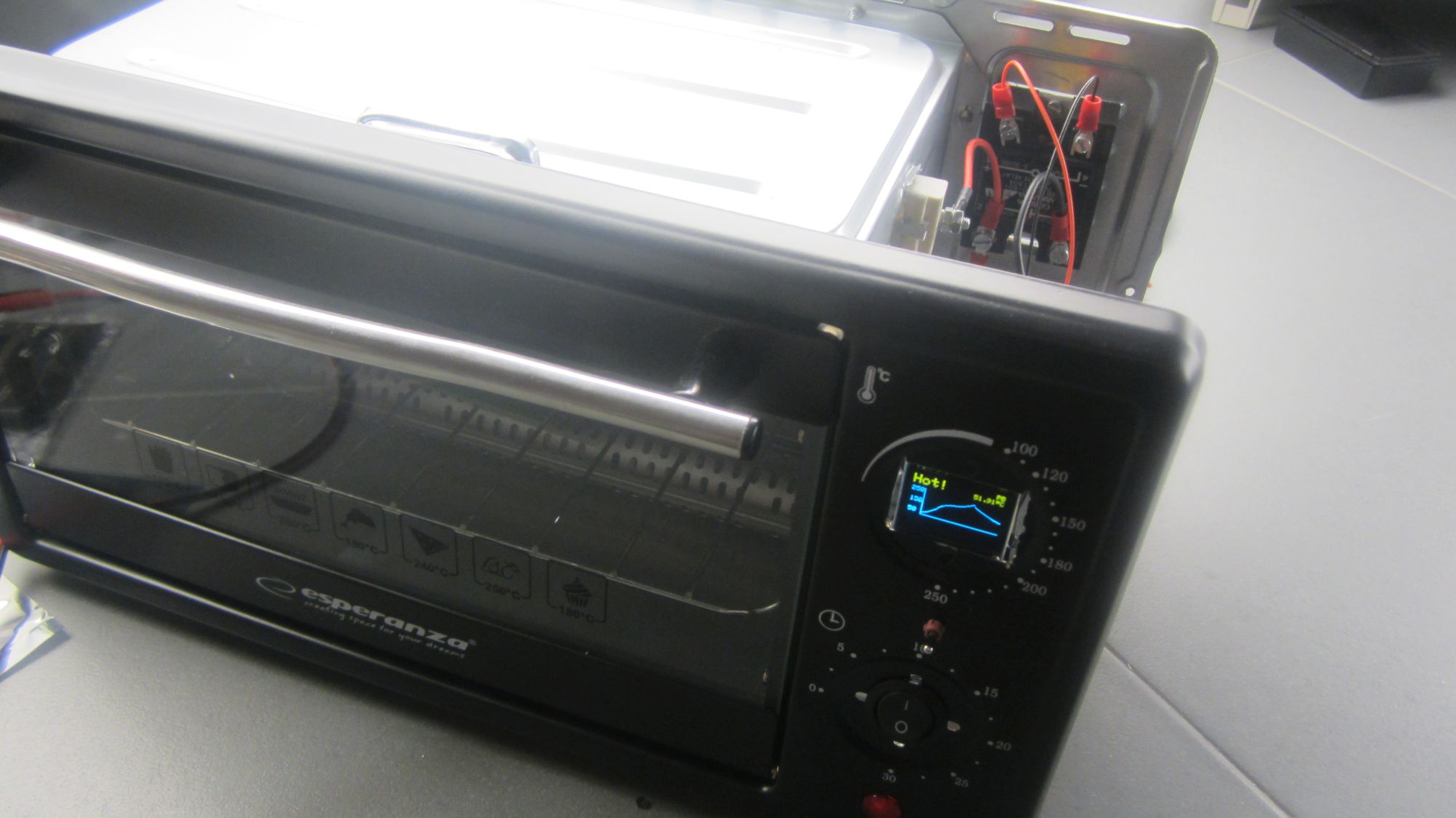
We installed the Tiny Reflow Controller v2 on a small oven rated at 900W and we tested its performance. As you can see in the photos below the reflow controller is installed on the front face, with the solid-state relay and the mini 5V power supply on the back. We were going to also install a cooling fan, but according to advice from the project author, natural cooling works better and stresses the components at a minimum. Also, the FAN output of the board isn’t implemented on the firmware so it would need some additional code to make it work. So, we decided not to install a fan at this moment.
Reflow Results
As we said before the board supports two reflow profiles, a PB and a Lead-free (LF), both selected before the reflow cycle starts. The controller has an onboard serial to USB converter, so to capture the data during the reflow, all you need is to connect a USB cable, launch your favorite RS232 terminal, set the serial config tot 115200 bps 8N1 and you are ready to go. Upon pressing the start button, temperature data is logged on the terminal along with time, setpoint and heating elements ON time. We tested both profiles by doing a full reflow cycle for each one and we share the results here. During our initial tests, we experience some issues, like we couldn’t successfully complete a reflow cycle, followed by an Error on screen. This could mean that the thermocouple touched a conductive part of the PCB, that shortcircuit it, or the TC was disconnected from the board or that there was more noise on the power rail that the board could tolerate. It proved that our case was the noise issue and that after replacing the USB cable with one that had a ferrite bead in line, the reflow cycle was completed successfully.
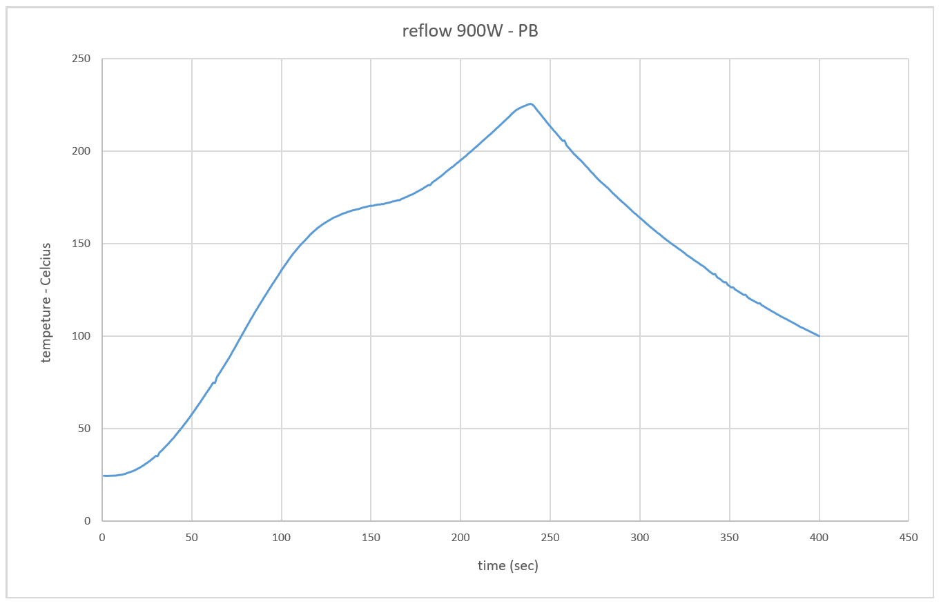
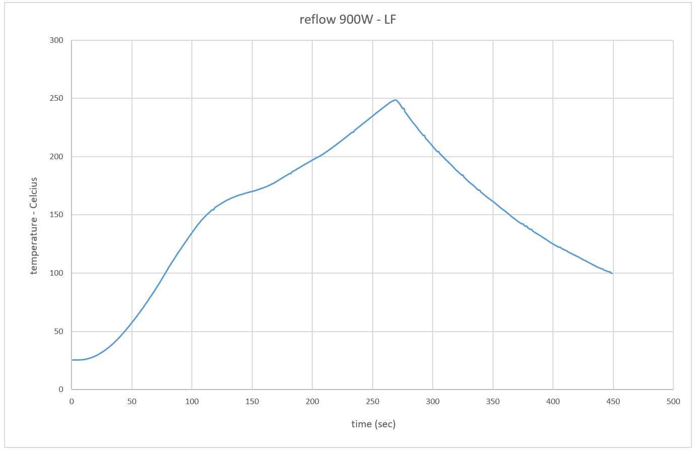
As you can see from the graphs above, both profiles start from room temperature (25ºC) and reach the soak phase after around 115 sec. Then the reflow stage starts and reaches 220ºC for PB and 245ºC for LF. We see that both profiles are smooth and clean and that could guarantee that your reflow soldering could be successful.
Video
Conclusion
The major difference between the TinyReflow Controller v2 and the v1 is the use of the OLED display which displays a Graph of the reflow process and the built-in USB-Serial interface which takes away the need for a converter when programming the board.
Looking for a good reflow oven that works well with this controller? You can go through this list curated by Rocket Stream to get suggestions on the best kind of ovens to use with the tiny reflow controller or visit their eshop to purchase an already assembled and tested board.
That’s it for today’s tutorial. Thanks for reading. As usual, feel free to reach out to me via the comment section if you have any question about the project and also let me know if you made one using this guide.


")


How can one adjust the time for different stages of the process? For example, preheat to last 120sec, soak – 90sec etc…
This is done automatically and dynamicly from the PID algorithm. You don’t have to set this on the software.
Hello Mike.i build that but for a bga machine(controls the 450w top IR ceramic element). but the process is too quick because the strong heating element. i try diferent PI valoes(without mess with D too much) but still too fast like 2 minuts for entire reflow/reball.
how can i know what values are best to a slow heating up?
ok.i end up with p=30 and i=0.20 for preheat and bit more on soak and reflow like p30-i0.25
hello, I decided to repeat the project, but unfortunately it does not display it. a low level appears on d2. the image appears after commenting out the debounce function. Please help me with the problem. thanks