Under Voltage and Over Voltage Monitor for 5V
- Rajkumar Sharma
- 244 Views
- easy
- Tested
- SKU: EL124986
- Quote Now
- 0 Likes

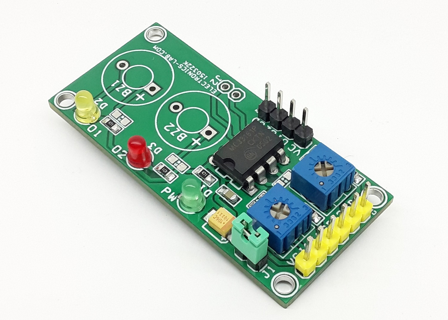
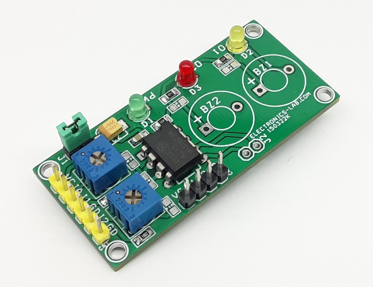
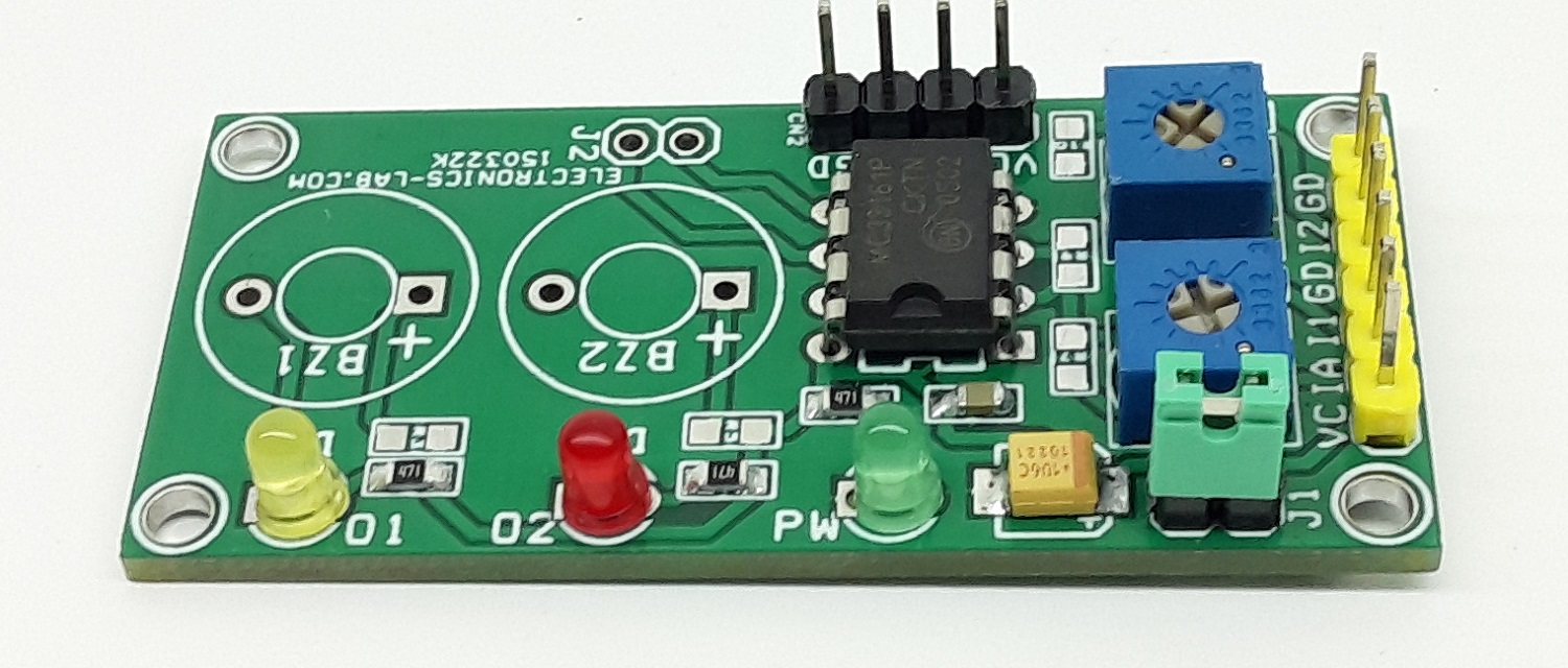
This project is built using MC33161 IC, which is a universal voltage monitor intended to be used in a wide variety of voltage sensing applications. The project offers an economical solution for positive and negative voltage detection. The circuit consists of two comparator channels each with hysteresis, a unique Mode Select Input for channel programming, a pinned out 2.54 V reference, and two open collector outputs installed with LED for visual alert for under-voltage and over-voltage situations. The project is configured for a 5V supply by default. It provides a visual indication when supply is lower the 5V and over 5V. Yellow LED indicates undervoltage and Red LED indicates overvoltage. Trimmer potentiometers PR1 and PR2 were provided to adjust the Undervoltage and Overvoltage range. Both inputs can be used as independent or combined (Single Input)
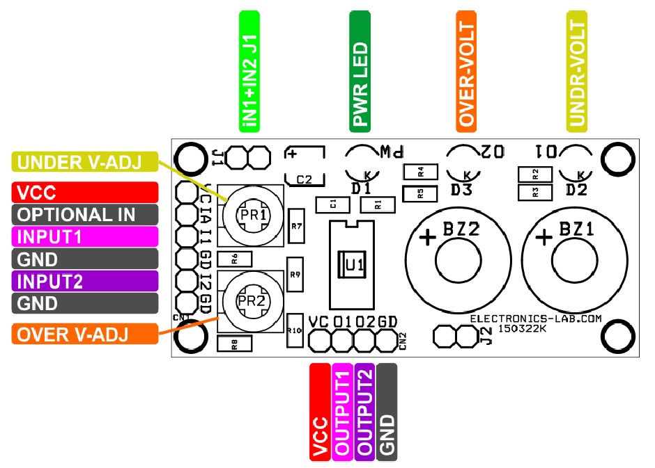
Connections
- D1 Power LED – Green
- D2 Under Voltage Alert LED – Yellow
- D3 Over Voltage Alert LED – RED
- CN2 Pin1 VCC, Pin2 Output 1, Pin 3 Output 2, Pin 4 GND
- Jumper J1 Single or Independent Input Selection (Dual)
- CN1: Pin 1 = VCC, Pin 2 = Optional, Pin 3= Input 1, Pin 4 = GND, Pin 5 = Input 2, Pin 6 = GND
- PR1 Trimmer Potentiometer – Under Voltage Range Adjust
- PR2 Trimmer Potentiometer – Over Voltage Range Adjust
Testing the Circuit
Close Jumper J1, Connect the 5V DC power supply to CN1 Pin1 +VC and Pin6 GND. Set the Adjustable power supply to 4.5V DC and connect it to Pin 3 or Pin5 of the CN1 Connector. Turn the PR1 trimmer potentiometer carefully so the Yellow LED glows, now set the adjustable power supply to output 5.5V and turn the trimmer potentiometer PR2 such Red LED D3 should glow. Now, the project is configured and ready to be used. It is set to detect and indicate undervoltage of 4.5V and Over voltage of 5.5V. Connector CN2 can help for microcontroller interface, Output 1 and Output 2 Normally goes High or low when under/over voltage conditions are detected.
Features
- Power Supply 5V DC (Range 5 to 12V DC)
- Yellow LED for Under Voltage detection
- Configured for 5V Detection
- Red LED for Overvoltage Detection
- Provides Visual Alerts when Under-Over Voltage is Detected at input 1 and Input 2
- Output 1 and Output 2 for Micro-Controller Interface
- LEDs can be Replaced with Audible Buzzer (Low Current Buzzer 10mA maximum)
- 4 X 2.5 MM Mounting Holes
- PCB Dimensions 53.66 x 24.92mm
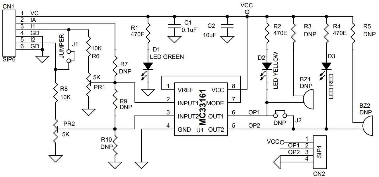
Schematic
Parts List
| NO. | QNTY. | REF. | DESC. | MANUFACTURER | SUPPLIER | PART NO |
|---|---|---|---|---|---|---|
| 1 | 8 | BZ1,J2,BZ2,R3,R5,R7,R9,R10 | DNP | DO NOT INSTALL | ||
| 2 | 1 | CN1 | 6 PIN MALE HEADER PITCH 2.54MM | WURTH | DIGIKEY | 732-5319-ND |
| 3 | 1 | CN2 | 4 PIN MALE HEADER PITCH 2.54MM | WURTH | DIGIKEY | 732-5317-ND |
| 4 | 1 | C1 | 0.1uF/50V SMD SIZE 0805 | YAGEO/MURATA | DIGIKEY | |
| 5 | 1 | C2 | 10uF/16V SMD SIZE 1210 CERAMIC OR TANTLUM | MANUFACTURER | DIGIKEY | |
| 6 | 1 | D1 | 3MM LED GREEN | AMERICAN OCTO | DIGIKEY | 2460-L314GT-ND |
| 7 | 1 | D2 | 3MM LED YELLOW | AMERICAN OCTO | DIGIKEY | 2460-L314YD-ND |
| 8 | 1 | D3 | 3MM LED RED | AMERICAN OCTO | DIGIKEY | 2460-L314HD-ND |
| 9 | 1 | J1 | 2 PIN MALE HEADER PITCH 2.54MM | WURTH | DIGIKEY | 732-5315-ND |
| 10 | 2 | PR1,PR2 | 5K TRIMMER POTENTIOMETER | BOURNS | DIGIKEY | 3362H-502LF-ND |
| 11 | 3 | R1,R2,R4 | 470E 5% SMD SIZE 0805 | YAGEO/MURATA | DIGIKEY | |
| 12 | 2 | R6,R8 | 10K 1% SMD SIZE 0805 | YAGEO/MURATA | DIGIKEY | |
| 13 | 1 | U1 | MC33161 DIP8 or MSOP8 | ONSEMI | DIGIKEY | MC33161DMR2GOSCT-ND |
| 14 | 1 | J1/SHUNT | SHUNT | SULLINS CONCT | DIGIKEY | S9001-ND |
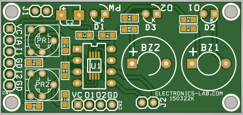
Connections
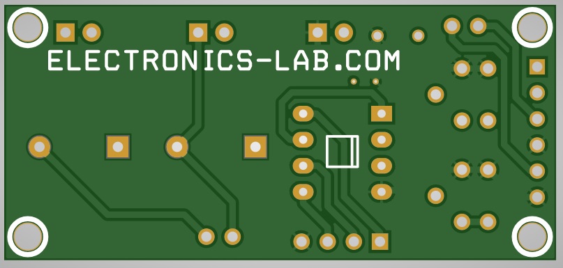
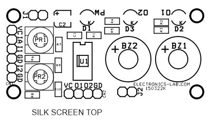
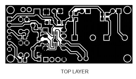
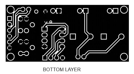
Gerber View
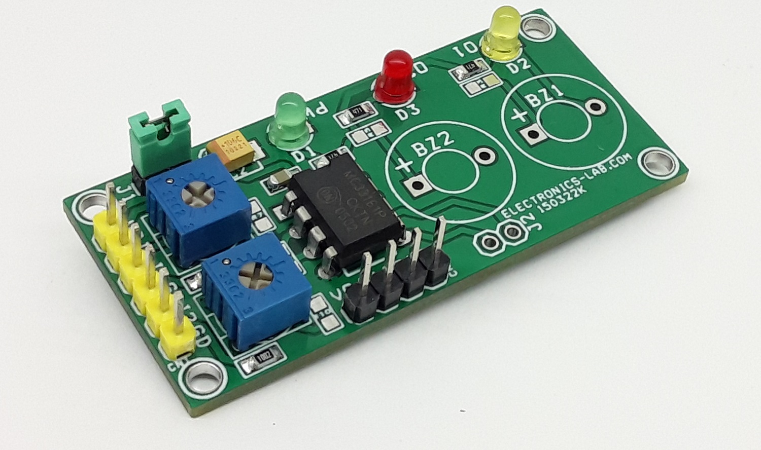
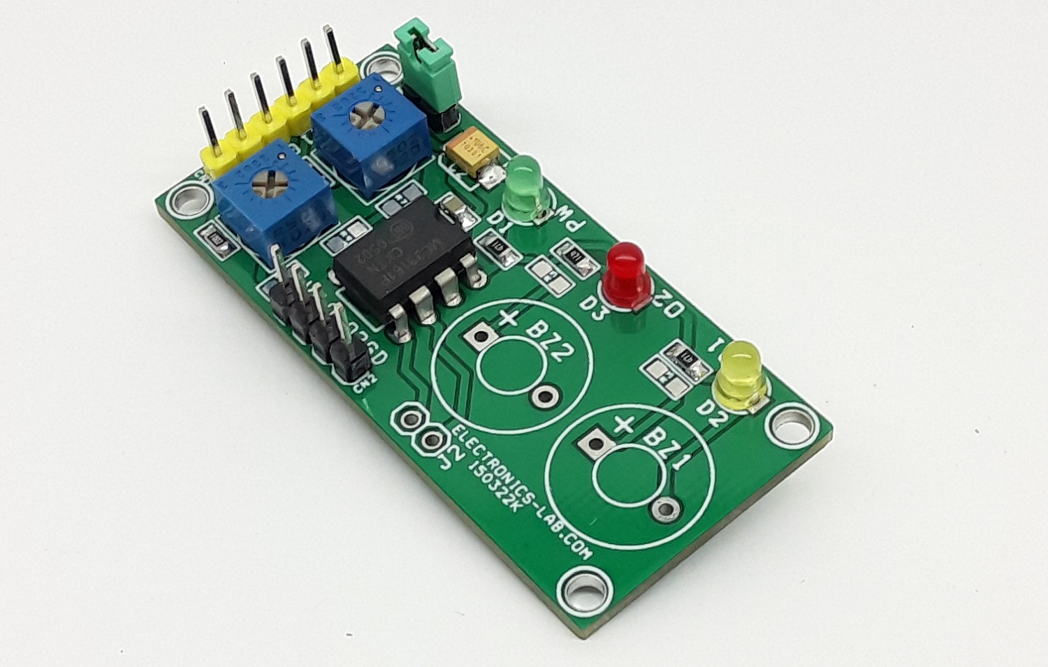
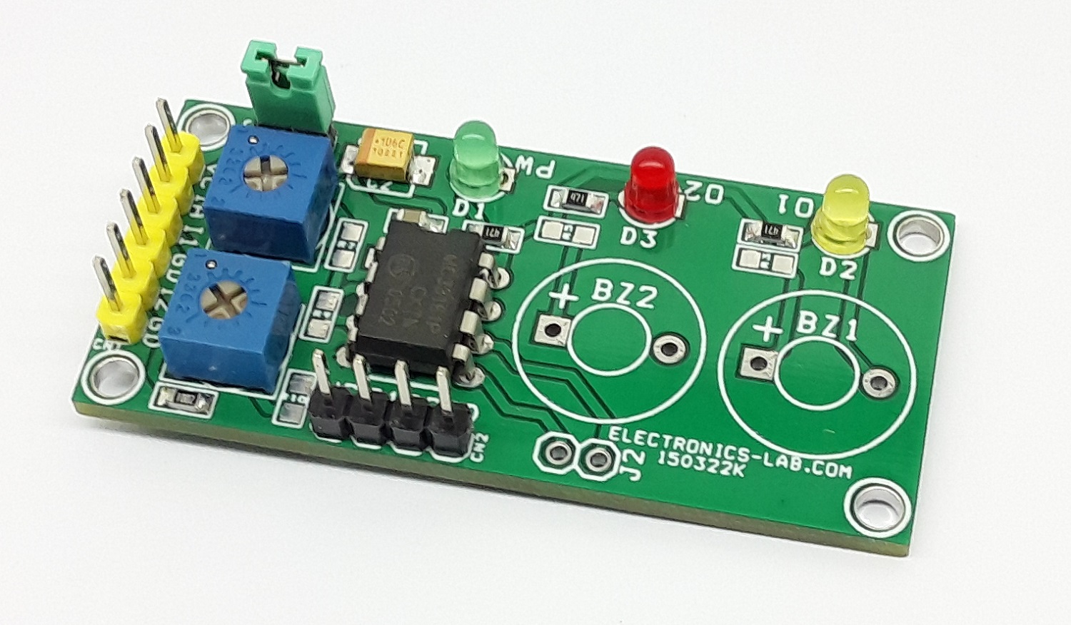
Photos
Video
MC33161 Datasheet
PCB