
Motion Activated Led Dice
- Rui Cabral
- http://www.ruijc.webnode.com
- rui.j.cabral@googlemail.com
- 18.867 Views
- moderate
- Tested
- 0 Likes

Introduction
I’ve always wanted to build an electronic led dice, but something different from what we see on the internet. Making it motion controlled… now that’s new! Many new cell phones that have accelerometers built in also have dice games. These dice move when shaking the cell phone. My Led Dice project will also work with a shake motion but without the use of the expensive accelerometers.
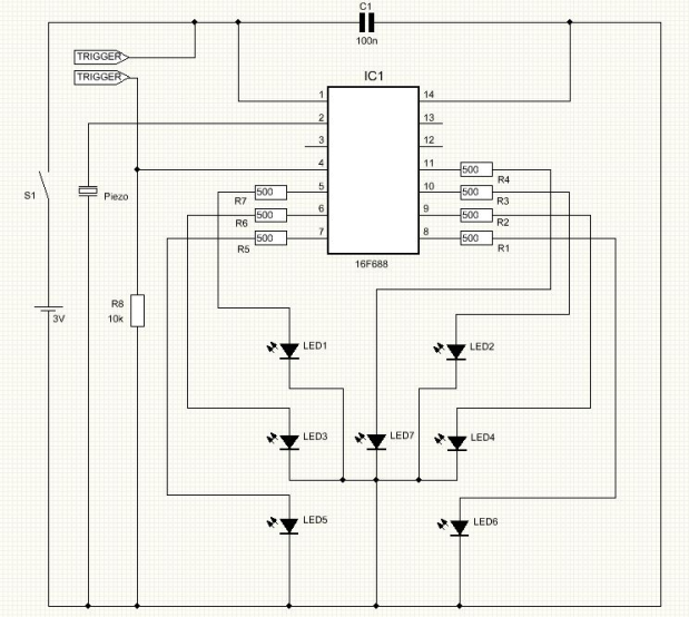
Parts List
R1 500 ohms resistor
R2 500 ohms resistor
R3 500 ohms resistor
R4 500 ohms resistor
R5 500 ohms resistor
R6 500 ohms resistor
R7 500 ohms resistor
R8 10K resistor
C1 100nF cap
Led1 to 7 5mm flat led
Piezo Piezo HPE-120
IC1 16F688 microcontroller from Microchip
S1 Normal On/Off switch
Others:
Box
AAA x2 battery support
PCB
Spring, screws and wire
Hex program for the microcontroller
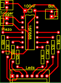
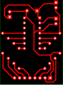
PCB
The PCB used for this Project is single layer and its size is 31.27 mm x 42.25mm.
I’ve used x2 AAA batteries to supply 3V to this circuit making it small and light.
Download PCB files at the bottom.
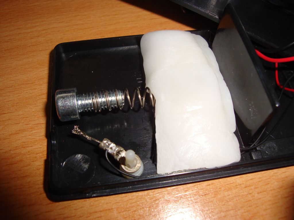
The Trigger
The trigger is a mechanical device and it will sense the shaking movement. One contact will be on a spring and the other contact will be on a wire. The spring has a screw on it’s end and it will act as a weight. Placing the box on it’s side, the spring needs to have enough strength not to bend with it’s own weight. Shaking will make the spring to move and touch the wire closing the circuit and this way the microcontroller will know when it’s time to roll the dice.
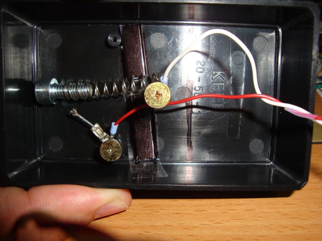
Adding a small amount of polymorph will secure the spring and give a better final look.
Hex Programm
The Hex program must be saved in the microcontroller’s memory before soldering on the PCB.
The fuses OSC and MCLR fuses must be set as follow:
INTOSCIO on
MCLR off
Testing
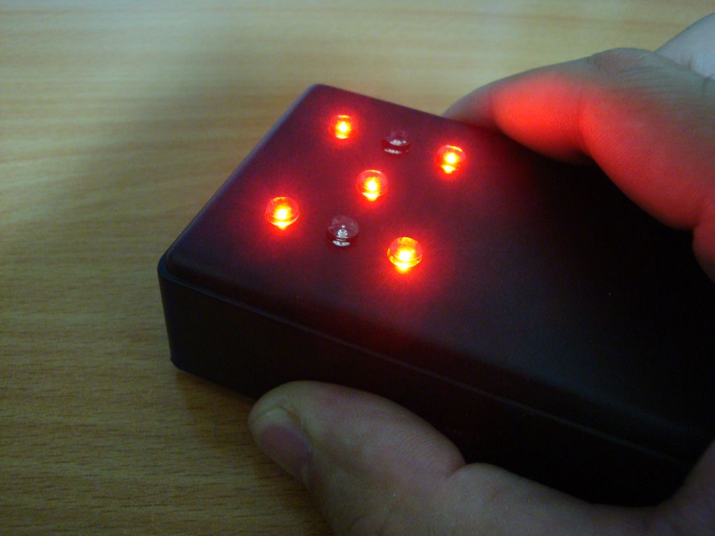
Turning on the circuit, the microcontroller will initialize and light on and off all leds.
Shaking the box will roll the dice. The leds will simulate the rolling of the dice and the piezo will sound until the final number is displayed.
Once the final number is displayed it’s possible to sort another number simply by shaking the box again.
Conclusion
It’s a pretty cheap and easy to make circuit.
Will add more fun to any board game.
Please follow and like us:
PCB


i cant understand about trigger