

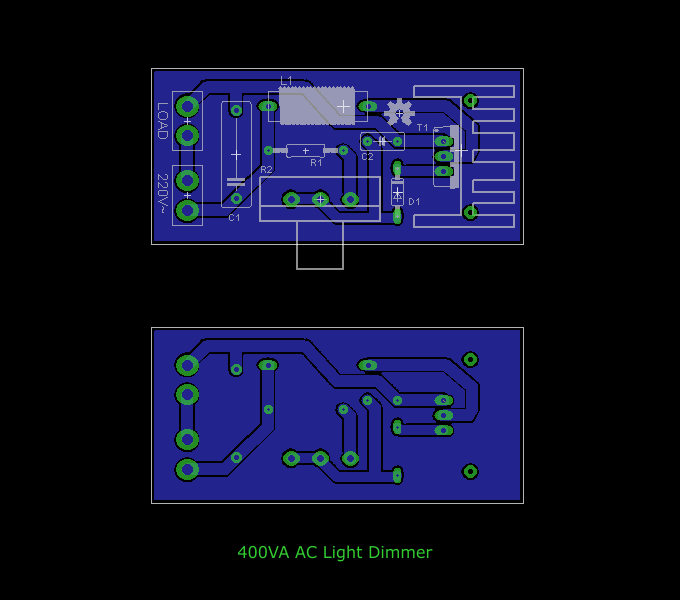
400VA AC Light Dimmer
- Michail Papadimitriou
- mixos@otenet.gr
- 50.830 Views
- moderate
- Tested
- 0 Likes

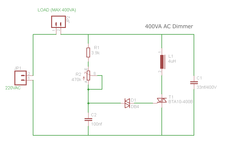
Schematic
Description
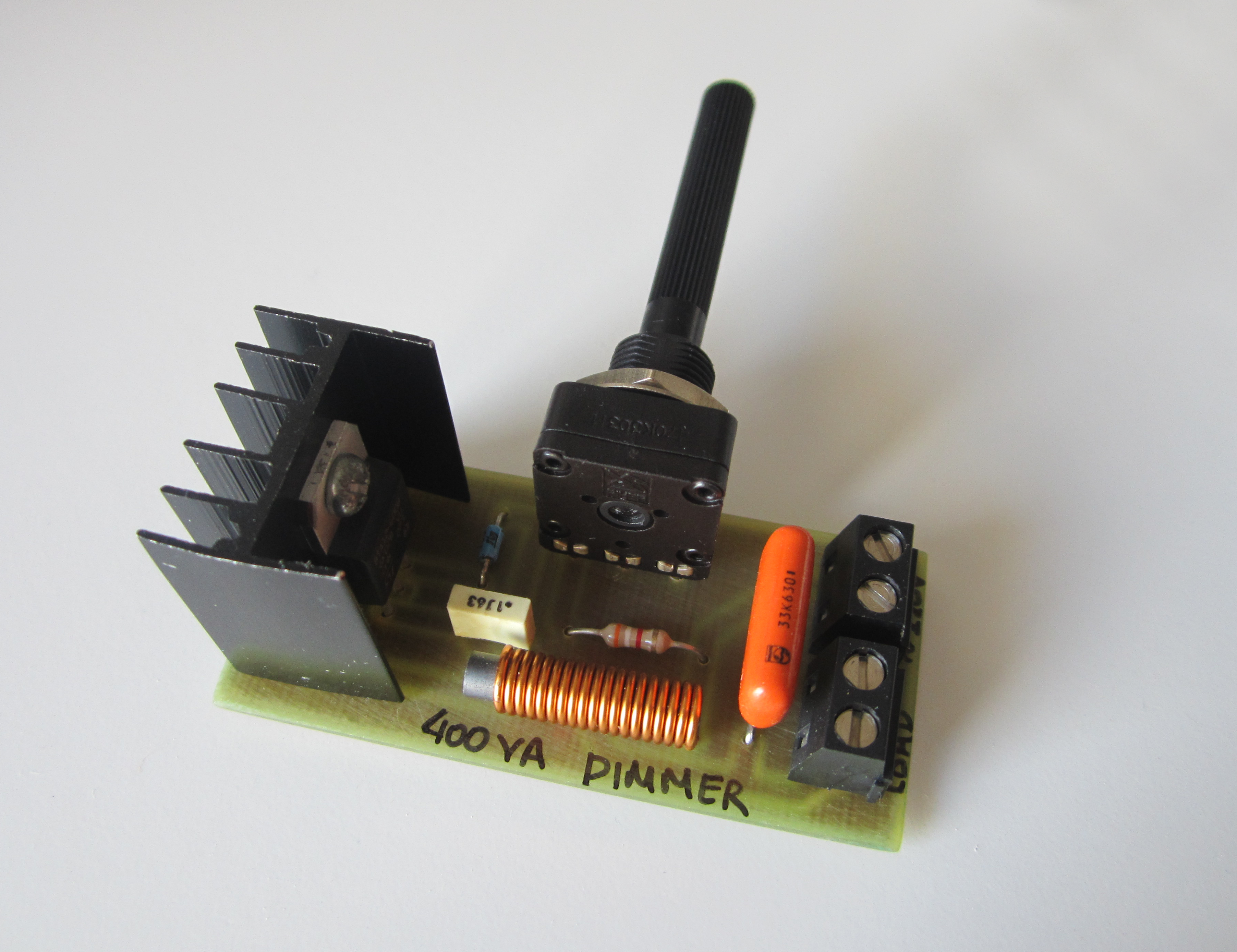
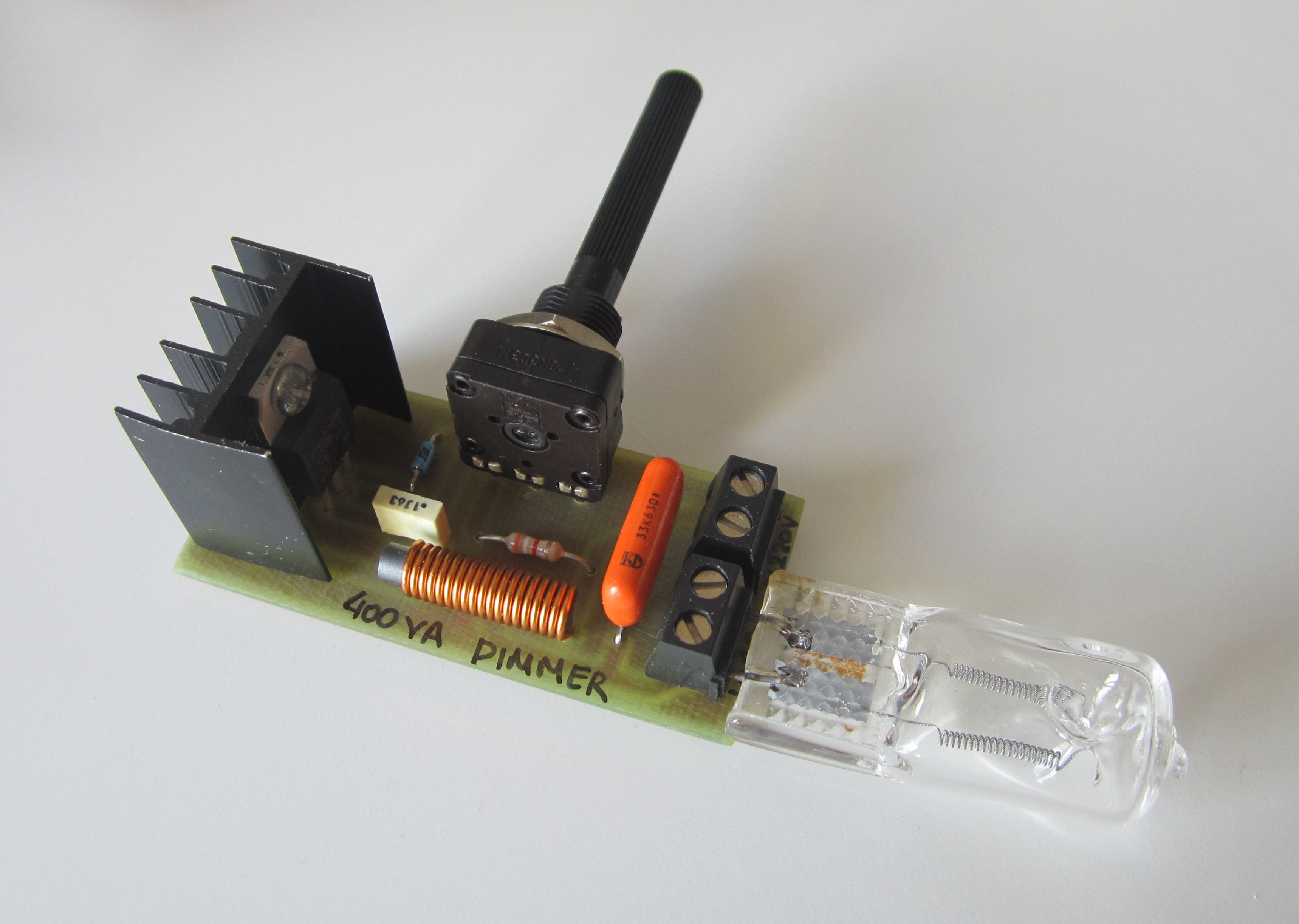
This is a simple TRIAC AC load dimmer used to control the power of a resistive load such as incandescent lamp or heater element. The max load it can handle is 400VA. Such a circuit is often found on cheap commercial light dimmers and is proven to work reliable for the rated power.
The circuit is working by controlling the phase of the 220VAC voltage allowing the load to be powered for less than 360º of the full sine wave. Powering the load for smaller period than full sine wave delivers less power, so it has a dimming effect on the load.
Control is done through R2 potentiometer which controls the time needed for the C2 to be charged through R1-R2. C2 is charging until it reaches the breakdown voltage of DIAC D1 which then fires the TRIAC T1. Once the TRIAC is contacting the circuit is closed and the load receives power.
The rate which C2 charges determinate the point on 220VAC sine-wave where it reaches the breakdown voltage of DIAC. So, slow C2 charging means that the DIAC conducts at the end of AC period and fast C2 charging means that DIAC conducts at the begging of AC sine.
Notes
- Components L1 and C1 act as interference suppression filter reducing RF emissions.
- Circuit is directly connected to mains voltage, so lethal voltages present all over the board. Take care!
- The potentiometer should have a plastic spindle to provide sufficient isolation.
Parts List
| Part | Value |
|---|---|
| R1 | 3.9K - 1/4W |
| R2 | 470K linear potentiometer |
| C1 | 33nF / 400V capacitor |
| C2 | 100nF polyester capacitor |
| L1 | 19 turns of 0.8mm enamel wire on 4mm ferrite core |
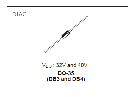
| D1 | DB4 diac |
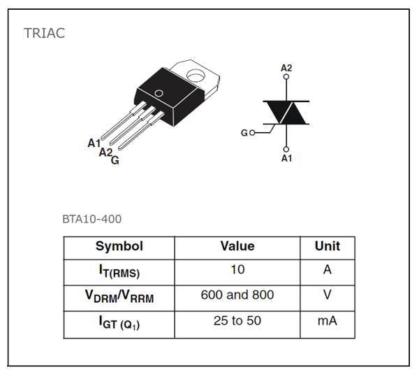
| T1 | BTA10-400B triac |
| heatsink for T1 | |
| PCB screw terminals |
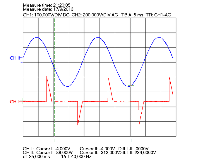
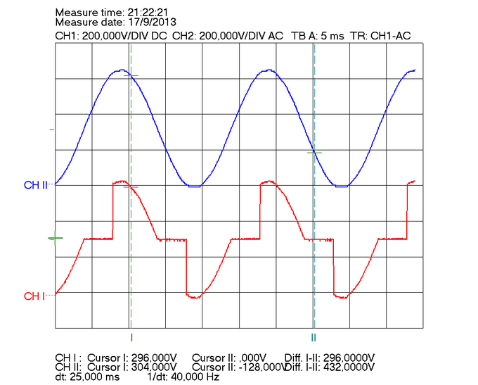
Measurements
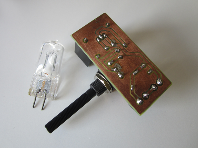
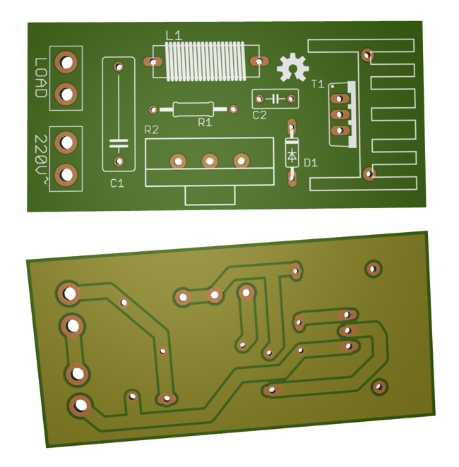
PCB


Could you please provide the calculations for choosing the values of R1, VR2, C2 (the TRIAC firing circuit)