How to run my laser diode?

grkmr

Jan 31, 2011
13
Joined
Jan 31, 2011
Messages
13
Hi guys,

I bought a laser diode from internet. Its seller says those:

Safety Instructions:

1 Note: This laser diode may do harm to human eyes, when the laser tube is working, pay no direct attention to it.
2, The laser tube requires a suitable power supply, transient reverse current can`t exceed 25μA, reverse voltage can`t exceed 2V, otherwise it will damage the laser tube.
Plugged in before power up, initial output voltage should be 0V, the current regulation should be increased or decreased slowly to prevent impact damage to the laser tube.
Test the laser tube: insert or pull out the laser tube after the power off. Do not plug or unplug the laser tube when the power on, otherwise the laser tube will be damaged, invalid.
3, The laser tube should be kept or working in a dry environment to prevent condensation, condensation may damage the laser tube.
4, At high temperatures, it will increase the threshold current, lower the efficiency and accelerate the aging of the laser tube.
5,When the output power higher than the specified parameters, it will accelerate the aging of the laser tube.
6, The laser tube need to be used in fully heat or cooling conditions
7, Laser diodes are ESD sensitive device, anti-static measures should be prepared. Before pick up the case, make sure you get a good grounding condition, otherwise the laser tube will be easily to breakdown by the static electricity, resulting in the laser tube failure. Wear anti-static wrist strap when working with the laser.


As seen above, he says that u should not use more than 2V and current must be 25 micro amps. I connected 60k ohm to a 1.5V battery which must create a current of 25 micro amps, and connected it to my laser diode module, but nothing happened. When I changed my adjustable resistor to 0 ohm, I saw a weak red light instead of a powerful 100mW laser beam. I think I might need a driver circuit but I dunno how to build it. I did not put the link of the product over here in order not to advertise, but I can send it as a private message to those who are interested in.

Thanks...
 

climatex

Jul 14, 2011
37
Joined
Jul 14, 2011
Messages
37
25 microamps? What kind of a laser diode is that?! I'm pretty sure he meant mA...

Voltage does not matter, really. All you need is to have your voltage bigger than 2V (that should be the voltage drop on the diode itself), or else it WON'T WORK so let's say with 6 volts you subtract two to get 4, then you divide 4 : 0,000025 to get a 160k value for your resistor. Which is pretty funky and outright stupid. Give it a 1mA and see if it lights up.

It's like a normal LED diode, let's say. There's no "maximum voltage". I light up LEDs normally from 325V DC or 20 000 V dc, let's say. Current limited. Also I have been powering up DVD-RW laser diodes with 150 mA of current. When focused, it was igniting matches within a second ;)
 

climatex

Jul 14, 2011
37
Joined
Jul 14, 2011
Messages
37
And also it is weird that he has written "laser tube". You know, some decades ago, 4-5 or so, there were no semiconductor lasers and for example 1-5 mW laser "pointers", which were specially designed vacuum tubes, operated at high voltage with low current (in microamps).
 

Resqueline

Jul 31, 2009
2,848
Joined
Jul 31, 2009
Messages
2,848
It's a generally bad translation (so you can ignore "tube"), but observe that the the 2V & 25uA is the maximum reverse spec', not the forward operating spec'.
 

climatex

Jul 14, 2011
37
Joined
Jul 14, 2011
Messages
37
Which n00b would put a laser-, or any kind of light-emitting-, diode in reverse? lol :D
 

grkmr

Jan 31, 2011
13
Joined
Jan 31, 2011
Messages
13
I tried it with 3V and no resistance. It works like crazy but gets hot like crazy too. When I use 1K with 3V, it barely turns on. May a stone resistor solve the problem? What do u think?
 

climatex

Jul 14, 2011
37
Joined
Jul 14, 2011
Messages
37
DO NOT EVER ATTEMPT TO RUN A LASER DIODE WITH NO CURRENT LIMITER such as a resistor !!!

Give us a datasheet of your diode so we can tell you the approximate working current.
 
Last edited:

Resqueline

Jul 31, 2009
2,848
Joined
Jul 31, 2009
Messages
2,848
Running from what voltage? 3V? No good.. You'll have essentially no control over the current.
As you can see from the datasheet the forward voltage drop is normally 2.4V but can be as high as 3V.
At the same time the current is supposed to 135mA, not less than 75mA, & no more than 150mA.
Running on 3V and 4.7 ohms could give you 128mA but it might also give you much less than 75mA or more than 150mA.
With 4.5V and 16 ohms you may get 131mA, not less than 94mA, & not likely more than 150mA.
Good laser drivers have an active electronic current control, keeping it stable over a wide operating voltage range.
 

TBennettcc

Dec 4, 2010
292
Joined
Dec 4, 2010
Messages
292
It says the operating voltage... does that always mean the forward voltage drop?

If there are so many variables, like you say, what would be the best way to make it work within spec'?
 

Resqueline

Jul 31, 2009
2,848
Joined
Jul 31, 2009
Messages
2,848
It's a required fundamental knowledge that with the steep I/U slope + temperature dependency of semiconductors you can't feed them a voltage, you feed a current.
Unlike LED's which work down to 0.1mA or less, laser diodes have a substantial minimum current below which they simply don't lase at all. Here 65-75mA.
Like I mentioned above, LASER (& LED ) drivers are usually constant current circuits. Fluorescent (& CCFL) tube ballasts are also constant current drivers. Those tubes have a negative internal resistance and would simply explode if fed a constant voltage.
 

climatex

Jul 14, 2011
37
Joined
Jul 14, 2011
Messages
37
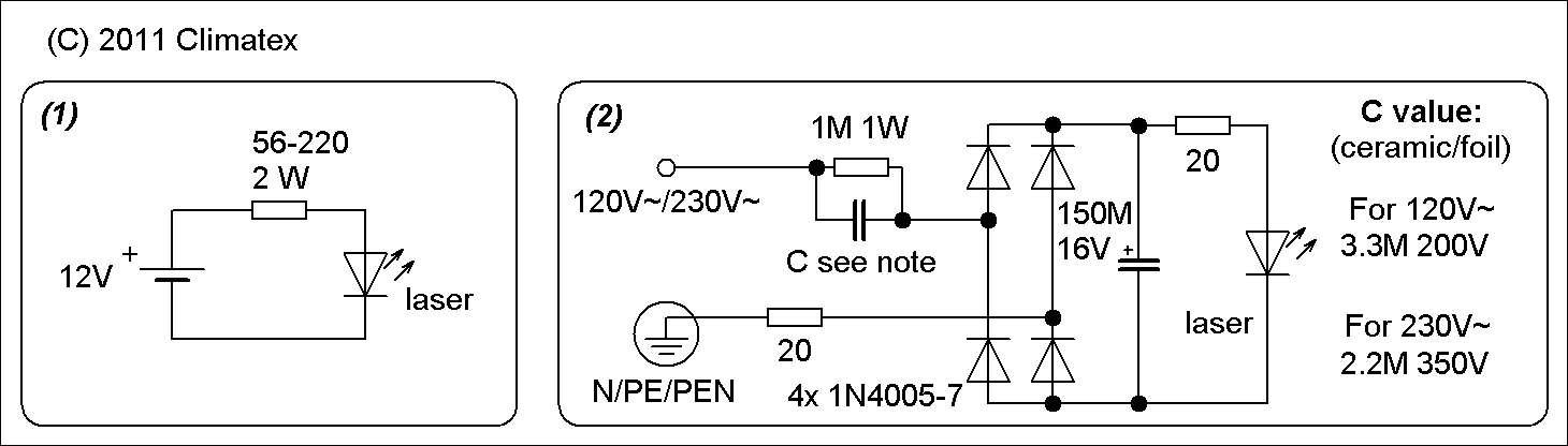
WARNING -- This post suggests a technique which can be very dangerous if you don't know what you're doing. Connecting LEDs to the main the way climatex suggests will cause the entire circuit to operate at mains potential.

Here are two convenient ways of doing it, folks. I hope he has at least a 12V source if he's a beginner, but the second option is transformerless (output current ca. 150 mA).

Enjoy, folks:
16lwv4p.png
 
Last edited by a moderator:

(*steve*)

¡sǝpodᴉʇuɐ ǝɥʇ ɹɐǝɥd
Moderator
Jan 21, 2010
25,510
Joined
Jan 21, 2010
Messages
25,510
I'm *really* not keen on running LEDs from the mains like that.
 

TBennettcc

Dec 4, 2010
292
Joined
Dec 4, 2010
Messages
292
Wow. That's wild. So you could really run an LED off 120V, as long as the current is kept at 20mA or so?

Climatex, could you explain your second circuit? Why do you have the 1M resistor and the capacitor in parallel? I understand the rectification, but then your capacitor across the LASER is only rated for 16 volts?

What's the label on the ground (N/PE/PEN) stand for?

Thanks for your time.
 

climatex

Jul 14, 2011
37
Joined
Jul 14, 2011
Messages
37
Yay, at least somebody who isn't a child frightened by mains. Here goes:

You don't drive a LED with voltage. There's only the minimum voltage that you are able to run the LED on, and that's her voltage drop. Standard red LEDs have e.g. 1.55V, green 2.0-2.3V, laser diodes 2.15 IrDA, 2.5V red ones, high luminiscent more than 3V and so on. If you want your LED to light up, your voltage source must supply a BIGGER voltage than her drop.

You drive the LED with current flowing through, computed from Ohm's law with supply voltage minus the voltage drop. Most small LEDs light up at 0.8-1mA of current and have a maximum of 20 mA. In all means, you have to limit the current passing through (like with a resistor, constant current source and so on), or else you might fry it. But I think you know this already.

The trick here is capacitive reactance. If you imagine a standard resistor in series with mains 230V 50Hz limiting the current to 150 mA, there's almost 34.5 VAs of heat loss on that resistor, simply said. In this circuit, the non-polarised capacitor has it's own resistance to the alternating current, in this case the 2.2M cap gives the 50Hz current a resistance of 1446 ohms, thus limiting the current to approximately 160 mA. The mains is then rectified by a bridge rectifier and the laser diode is in parallel with the filtration cap, her voltage drop acts like a "voltage limiter" for the capacitor - which will charge up to 8V in this case. (Without the diode present it would slowly charge up to 325 V.)

The 1 megaohm resistor across the limiter capacitor is just to discharge the cap after it's unplugged. The two 20 ohm resistors serve as inrush current limiters for the capacitors, both the limiter and the filtration cap - the other one protects the laser diode from excessive current spike.

You can find capacitive reactance calculators online. Just beware that the capacitor MUST be non-polarized (foil, ceramic <-- DO NOT USE CERAMIC, etc), since AC flows through. And the minimum voltage rating for it should be = RMS supply voltage * sqrt(2) + some few volts extra for added protection.

N = neutral, PE=protective earth (TN-S system), PEN=protective earth + neutral combined. Just to indicate that you must connect the limiter cap to the live wire, not to the neutral/ground
 
Last edited:

climatex

Jul 14, 2011
37
Joined
Jul 14, 2011
Messages
37
In addition, I use this method to heat the filament of indirectly-heated vacuum tubes, if I don't have the proper heating transformer, for example. I just look at the heater current itself and then it doesn't matter whether the tube should be heated with 12V, 14V, 27V, 40V or so, just the current itself is critical. Plus, I don't use any rectifiers or smoothing caps when doing that.

This method of current limiting is efficient with currents up to 300 mA, that means a 4M7 cap with 230V~ mains. Bigger currents need greater capacities and at one point, the capacitor might get more bulky than a regular transformer, or a SMPS.

One neat trick:if you combine a cap this size (1M to 10M at 200 or 350V, depending on your mains) in series with a standard incadnescent lightbulb dimmer and an ignition coil from your car, you have a nice little high voltage supply there. /Won't kill you on contact, but gives you a nifty slap, so this trick might need a friendly warning about mains voltages mentioned, even with no schematic present.
 
Last edited by a moderator:

TBennettcc

Dec 4, 2010
292
Joined
Dec 4, 2010
Messages
292
I've been in ham radio since 2009. I've learned a lot (it's responsible for getting me this far in electronics), but I still have a long way to go. You talk about capacitive reactance; I've heard the term before, but I don't understand the concept yet. I know I will one day, though. (Especially working with and around radios and antennas.)

Can you explain more about how the diode limits the voltage across the capacitor? Maybe give me some more terms so I can go do some more research?

I've always heard it referred to as 'ground' or 'earth', but never 'protective earth'. Is there any of the above which is 'proper' or 'more proper' or 'more popular' than the other? (I did end up doing some research, and found the 'Earthing system' article on Wikipedia. Interesting.)

You sound like you are fairly educated on the subject. I appreciate you taking the time to teach me. Thank you.
 
Top