Hi,
I have an experimental task involving photomultiplier tube pulse analysis. The major part of the analog circuitry is to drive 16 parallel high-speed S&H amplifiers (significant current required while not compromising signal speed and waveform even a bit), so that should justify why I did not go with some generic op-amp, even though looking back there were much better choices than AD8000...
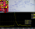
I have a clean 0.5-1V asymmetric Gaussian form pulse (rise time is 50 ns, fall time is 500 ns) coming from the LTC6268-10 amplifier. That's the input signal for the AD8000 amplifier I am struggling with. My setup for AD8000 currently is very simple: a non-inverting amplifier with a gain of roughly 3.2. However, the output signal becomes critically distorted (yet still fragments of Gaussian form are somewhat recognizable) with a huge voltage overshoot right around the peak of the supposed Gaussian signal, then there is the exponential voltage decay (bottom part of the attached picture). I am indeed observing an approximately correct voltage amplification factor, but the signal form is not acceptable for me. The setup should be as simple as putting 2 resistors in the feedback path, but after hours of testing, I am clueless about what's happening and causing this problem.
Things I have already tried:
1. Switching x1 and x10 passive oscilloscope probes and playing with the probe compensation trimmer capacitor. Also using a standard 10 cm ground clip as well as a short high-speed ground spring
2. Putting various 15 R to 50 R series dampening resistor values right at the AD8000 output, I tried disconnecting the load completely and measuring AD8000 output directly with no load.
3. Putting various fixed several pF capacitors across my feedback path resistors for intended frequency compensation
Nothing has changed the result considerably, only very mild overshoot dampening or pulse duration broadening, but not a fundamental solution. I also attach my circuit diagram right now as well as a small piece of my layout depiction. Please ignore the strange footprints for feedback resistors. At first I had another idea on my mind regarding the feedback for AD8000, but after observing that nothing actually works, I isolated the problem as much as possible and tried to achieve at least minimal/fundamental operation. I have solid decoupling, my supplies are +5V and GND, of course, a solid ground plane on layer 2. Just like I mentioned, I would not choose AD8000 for this task again, but since this is only a first revision device, I really need to make it work at least marginally well, so any help is much appreciated.
I have an experimental task involving photomultiplier tube pulse analysis. The major part of the analog circuitry is to drive 16 parallel high-speed S&H amplifiers (significant current required while not compromising signal speed and waveform even a bit), so that should justify why I did not go with some generic op-amp, even though looking back there were much better choices than AD8000...
I have a clean 0.5-1V asymmetric Gaussian form pulse (rise time is 50 ns, fall time is 500 ns) coming from the LTC6268-10 amplifier. That's the input signal for the AD8000 amplifier I am struggling with. My setup for AD8000 currently is very simple: a non-inverting amplifier with a gain of roughly 3.2. However, the output signal becomes critically distorted (yet still fragments of Gaussian form are somewhat recognizable) with a huge voltage overshoot right around the peak of the supposed Gaussian signal, then there is the exponential voltage decay (bottom part of the attached picture). I am indeed observing an approximately correct voltage amplification factor, but the signal form is not acceptable for me. The setup should be as simple as putting 2 resistors in the feedback path, but after hours of testing, I am clueless about what's happening and causing this problem.
Things I have already tried:
1. Switching x1 and x10 passive oscilloscope probes and playing with the probe compensation trimmer capacitor. Also using a standard 10 cm ground clip as well as a short high-speed ground spring
2. Putting various 15 R to 50 R series dampening resistor values right at the AD8000 output, I tried disconnecting the load completely and measuring AD8000 output directly with no load.
3. Putting various fixed several pF capacitors across my feedback path resistors for intended frequency compensation
Nothing has changed the result considerably, only very mild overshoot dampening or pulse duration broadening, but not a fundamental solution. I also attach my circuit diagram right now as well as a small piece of my layout depiction. Please ignore the strange footprints for feedback resistors. At first I had another idea on my mind regarding the feedback for AD8000, but after observing that nothing actually works, I isolated the problem as much as possible and tried to achieve at least minimal/fundamental operation. I have solid decoupling, my supplies are +5V and GND, of course, a solid ground plane on layer 2. Just like I mentioned, I would not choose AD8000 for this task again, but since this is only a first revision device, I really need to make it work at least marginally well, so any help is much appreciated.