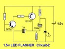
Capacitor charge pump

Ethernautica

Nov 6, 2026
1
Joined
Nov 6, 2026
Messages
1
Hypothetically, how could I add a second capacitor boost stage to this circuit to brightly flash blue/white LEDs?

Circuit is from the Talking Electronics website
 

Attachments

  • 1v5LED_Flasher-2 (2).gif
    1v5LED_Flasher-2 (2).gif
    4.2 KB · Views: 14

Delta Prime

Jul 29, 2020
2,996
Joined
Jul 29, 2020
Messages
2,996
Hypothetically you can't.
That is a high gain positive feedback, regenerative circuit,who's output voltage maximum would be 2.4 volts.
A jewel thief or blocking oscillator, boost converter circuit topology would be preferable. White and blue LEDs take More voltage to turn On.

Typical Forward Voltages by Color
• Red: 1.6V – 2.2V (typical ~1.8V – 2.0V)
• Orange / Yellow: 2.0V – 2.2V
• Green (Standard): 2.0V – 2.4V
• Green (True / High-Brightness): 3.0V – 3.5V
• Blue: 2.5V – 3.7V (typical ~3.2V – 3.6V)
• Violet / Purple: 2.76V – 4.0V
• White: 2.7V – 4.0V (often uses a blue/UV base with a phosphor layer)
• Ultraviolet (UV): 2.1V – 3.8V
 

AnalogKid

Jun 10, 2015
3,058
Joined
Jun 10, 2015
Messages
3,058
One might think that you could just add two diodes and two capacitors to the output, but no. The problem is that that circuit's output impedance, and its ability to drive a low impedance load such as a charge pump, is not symmetrical. The PNP transistor can pull up the output rapidly, but there is nothing to pull down the output because the LED now is downstream.

ak
 

josephii3

Dec 6, 2024
5
Joined
Dec 6, 2024
Messages
5
You could cascade another charge-pump stage using a second flying capacitor and two diodes, with another capacitor acting as the output reservoir. The main challenge is getting enough current for a bright LED pulse.
 

bidrohini

Feb 1, 2023
221
Joined
Feb 1, 2023
Messages
221
AnalogKid’s point about the recharge path is the first thing I’d address. Adding another capacitor stage is possible in principle, but it needs a drive waveform that can charge and reset the flying capacitor on successive cycles. The PNP’s strong pull-up alone doesn’t provide that once the LED is moved downstream.

A pull-down resistor could provide a return path, but its value would affect recharge time, battery consumption and potentially the oscillator’s operation. Simply adding two diodes and another capacitor doesn’t resolve those issues.

If you want to explore a capacitor-only solution, I’d separate the voltage multiplier from the flash timing: use an oscillator and output driver capable of sourcing and sinking current at the battery voltage, charge a reservoir capacitor, then switch a current-limited LED pulse from it. That lets the pump replenish the stored energy between flashes. An ideal doubler from 1.5 V only gives 3 V before losses, so there may be very little headroom for a blue or white LED at the desired current.

If two cells are acceptable, Talking Electronics already includes a “3v WHITE LED FLASHER” in its transistor circuits collection. That would be a useful capacitor-boost circuit to study before designing another stage.

For comparison, the Engineering Mindset Joule-thief project illustrates the inductive approach mentioned earlier. It powers a white LED from a low-voltage cell, but would need additional control to produce distinct, slow flashes.

Does the design have to stay with one 1.5 V cell, and roughly how long should each flash last? Those constraints would help determine whether another capacitor stage is practical.
 
Top