Hi there,
I would like some help with finding an effective way to detect resonance in an electrolysis setup that functions like an LC circuit. Let me lay out the full context and details. (The pics are not showing in the post in this order.)
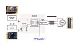
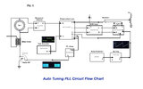
Pic 1 shows the flow chart for the setup that is built and based on an auto-tuning circuit designed by a friend, who is no longer working in this area, and is designed to help explore ways to improve the efficiency of Hydrogen production. At this stage, the two gases are not separated but that doesn't affect the way the pulsed supply affects the electrolysis reaction. The small test cell uses pure water and so operates like a capacitor and, with a choke either side, can be modelled like an LC tank circuit. Part of the aim is to cause dielectric breakdown of the pure water to split it at high voltage but very low current.
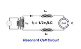
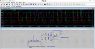
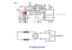
Pic 2 shows part of the circuit drawing that is related to detecting when resonance occurs in the cell and two chokes and which is the focus of my query.
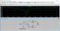
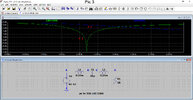
Pic 3 shows this modelled using LTSpice and that, when using typical values for L and C and a sine wave input, a resonant frequency occurs at 2.2996kHz.
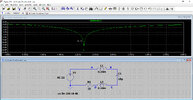
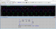
Pic 4 this shows what happens in the LC circuit when using a square wave input that is actually used for the electrolysis. Unlike when using a sine wave, at resonance, there does not seem to be a minimum impedance point that could be used to feed to a comparator.
Pic 5 shows the LC circuit modelled with the 'Resonance Detector' op-amp setup. The various traces are the square wave input (Green), inputs to the op-amp D, E (Red, Blue) that come from across the cell (Capacitor C1) and output F (Cyan) from the op-amp.
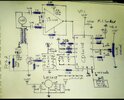
Now let me explain what happens in practice. The PLL circuit works fine (some of the traces are shown in Pic 1) on manual and where the frequency output is determined by the pot at the top right. However, on Auto, where the ramp generator results in a range of frequencies (0-20kHz) in the PLL's VCO, no output comes from the PLL chip (Pin 4). At the moment I am thinking that the PLL output may only appear in Auto mode when a resonance lock is made, but to fully understand how that lock arises I have been examining exactly what happens at resonance and how the circuit will detect it and feed a signal into Pin 14 of the PLL.
From my modelling with LTSpice, I can't see any particular feature at resonance across the capacitor (cell) that could be useful to tell the op-amp that resonance is taking place, especially with a square wave input. At least with a sine wave, I could have used the voltage across the whole circuit (L-C-L) to give me a definitive low value.
So to summarise my query, can I detect resonance with the current setup and pick off points or will some modest adjustment make that possible? Alternatively, perhaps I need to build some additional circuitry to enable this?
Ideas welcomed. Thank you


Last edited by a moderator:
