Electronics Boffins needed

Barbados1993

Sep 6, 2021
8
Joined
Sep 6, 2021
Messages
8
Help Needed!!

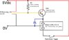
I’m trying to resolve a problem with this latch and release break beam circuit – with PNP transistor amplifier It works fine for a few minutes then consistently breaks down – as though the transistor is getting overheated?

It works again after about 20 mins.. It’s driving me nuts!

I’m not very clued up on transistor selection.. and mainly using what’s been available in a liitle selection pack.. then I have pages of scrawling’s which have lead me to arrive at resistor values – I’ve tried lots of transistors and different resistors but any combination which works still seems to fade away after repeated use.

It was suggested that I add a flyback diode – which I tried (in blue) this made no difference

Any help or advice greatly appreciated.

Lee Judd
 

Bluejets

Oct 5, 2014
7,374
Joined
Oct 5, 2014
Messages
7,374
Show a drawing of your circuit and photos of your setup including all wiring and power supplies.
What you have provided is akin to saying your car stopped, please fix. o_O
 

Harald Kapp

Moderator
Moderator
Nov 17, 2011
14,272
Joined
Nov 17, 2011
Messages
14,272
You're using the PNP backwards: the emitter of the PNP needs to go to +5 V, collector to the relay. Swap emitter and collector.
 

Bluejets

Oct 5, 2014
7,374
Joined
Oct 5, 2014
Messages
7,374
The ada2168 is an open collector device so with the 470 ohm that is ok...
but you don't have any base resistor in series with the transistor base lead after R1.
Try maybe 220ohm in there.
Yeah, a-about transistor...o_O
 

Barbados1993

Sep 6, 2021
8
Joined
Sep 6, 2021
Messages
8
The ada2168 is an open collector device so with the 470 ohm that is ok...
but you don't have any base resistor in series with the transistor base lead after R1.
Try maybe 220ohm in there.
Yeah, a-about transistor...o_O
hi guys this seems to have worked so thank you very much can you tell me how you worked out what resistor to use
 

AnalogKid

Jun 10, 2015
3,045
Joined
Jun 10, 2015
Messages
3,045
For firm saturation (lowest power dissipation), the old rule of thumb is that the ratio of a transistor's collector current to base current should be 10:1. But this isn't the 1950's, so I start with 20:1 - ish.

Start with Vcc.

Subtract the base-emitter junction voltage (Vbe).

Subtract the sensor's low output voltage.

The result is the voltage across the base resistor.

Calculate the resistor value for a current of 1/20th of the relay coil nominal current at 4.9 V (Vcc - Vcesat). Move down to the next lowest real world value.

Use that resistor value to calculate its current, and verify that this is within the operating range for the chosen transistor.

ak
 

Barbados1993

Sep 6, 2021
8
Joined
Sep 6, 2021
Messages
8
hi thank you for your responses we have changed the listed things above but we still find our self with the same problem we think are board is getting hot from the relay some one has suggested we try using a MOSFET to stop the relay getting hot do we think this will work or any more ideas thank you for your help
 

bertus

Moderator
Nov 8, 2019
3,837
Joined
Nov 8, 2019
Messages
3,837
Hello,

As the used relay is a latching relays. a short pulse would be enough to activate.
The coil takes about 150 mA at 5 Volts, so it will dissipate 0.75 Watt.

Bertus
 

Attachments

  • en-g5rl_uk short.pdf
    151.3 KB · Views: 3

Bluejets

Oct 5, 2014
7,374
Joined
Oct 5, 2014
Messages
7,374
it's really all wrong....the ir sensor is off and resistor R1 only turns off the top coil when the ir beam is broken.
 

Barbados1993

Sep 6, 2021
8
Joined
Sep 6, 2021
Messages
8
This is were I am with this now - but I still have the same problem as I had originally - The transistor seems to be unhappy after repeated triggers. The intention is that the relay is released when the IR sensor is 'broken' beam. Amp Diag4.jpg
I would be very grateful for any ideas on what I can measure to understand how to adjust the R values.. all any other suggestions please.. :(
 

Bluejets

Oct 5, 2014
7,374
Joined
Oct 5, 2014
Messages
7,374
Outline the way in which the circuit is supposed to work in your opinion.
I have my own idea but it may not be correct.
 

Barbados1993

Sep 6, 2021
8
Joined
Sep 6, 2021
Messages
8
Outline the way in which the circuit is supposed to work in your opinion.
I have my own idea but it may not be correct.
Hi, Bluejets.. The push button triggers the relay to 'made' - starting a motor. When the motor drive reaches a certain point, an armature breaks (and moves past) the break beam sensor - The relay is opened, stopping the motor, until it is triggered again.

This circuit works but isn't happy.. I'd love to be able to measure some values and calculate for better component values? Many thx
 

Bluejets

Oct 5, 2014
7,374
Joined
Oct 5, 2014
Messages
7,374
Yes, as I thought.
Circuit is crap.....needs redesign.
See what I can do...hope you're not in a rush.
 

Barbados1993

Sep 6, 2021
8
Joined
Sep 6, 2021
Messages
8
Bluejets.. thanks for your encouraging words.. It was designed with all the brilliance of fractional memories of electronics at school some 30 years ago.. coupled with a desk full of random components and trial and error.

I would be very grateful for some guidance. Days spent already trying to find some info or guidance on-line.. Many thanks
 

AnalogKid

Jun 10, 2015
3,045
Joined
Jun 10, 2015
Messages
3,045
The transistor is underrated for the task. It has a max collector current rating of 500 mA, but all of the characterization charts stop at 50 mA. The relay coil draws 150 mA. If you must stay with a small signal transistor, consider a 2N4403. Adjust R2 for a base current of between 10 mA and 15 mA, and increase R1 to 4.7 K.

Another approach is to add a small pulse-forming circuit between the sensor and the driver transistor. A bit more complex, but a big decrease in transistor power dissipation.

ak
 
Top