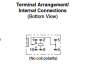
Is there someone who can explain how this relay works. It has six pins on it. What would you hook up to the various pins. I've enclosed the data sheet and a picture of the pin layout. I'm new at this and trying to learn. Thanks
The coil is between pins 2 <>9.
The common contact is shared on pins 5+6 (both are internally connected).
Pin 1 is the normally closed contact. When the coil is not energized, pin 1 is connected to Pins 6+6.
Pin 10 is the normally open contact. When the coil is energized, pin 10 is connected to Pins 6+6.
If mounting on a circuit board i would solder one of the coil contacts to ground and the other coil contact would be voltage coming in to activate the coil. Pins 5 and 6 would be the source coming in to be switched to either pin 1 or pin 10. Is this correct?
Yes, 2 & 9 are the coil, pin 1 is the normally close (N.C.), pin 10 is the N.O.
If using it in a sensitive environment, it is wise to wire a reverse biased rectifier across the coil.
Google BEMF diode.
M.