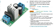
Diode bridge > filter capacitor > LM7812 regulator > output capacitor.
Circuit is in the datasheet.
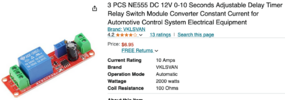
What is the relay coil resistance / current / power rating? Depending on this, the component values will change. AND the IC might need a heatsink.
Here is a typical circuit from the innergoogle. You do not need the transformer.
ak
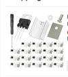
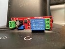
View attachment 65155